When you click on links to various merchants on this site and make a purchase, this can result in this site earning a commission. Affiliate programs and affiliations include, but are not limited to, the eBay Partner Network.
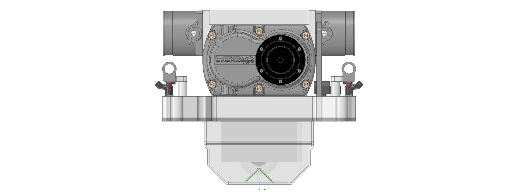
To scavenge all the hood clearance I could get, I did mount the supercharger from below.
Its not really an issue, as the entire manifold has been designed for future serviceability. Quick connects are used on all plumbing, so removing the manifold for bench service takes just a matter of minutes. No sealant is used anywhere, so the manifold spits easily. If an o-ring tears in the process, I am using off-the-shelf cord stock (plus I will includes spares with the kit for all o-rings, along with part numbers for replacement).
Getting closer - get my hands on the prototype intercooler tomorrow.
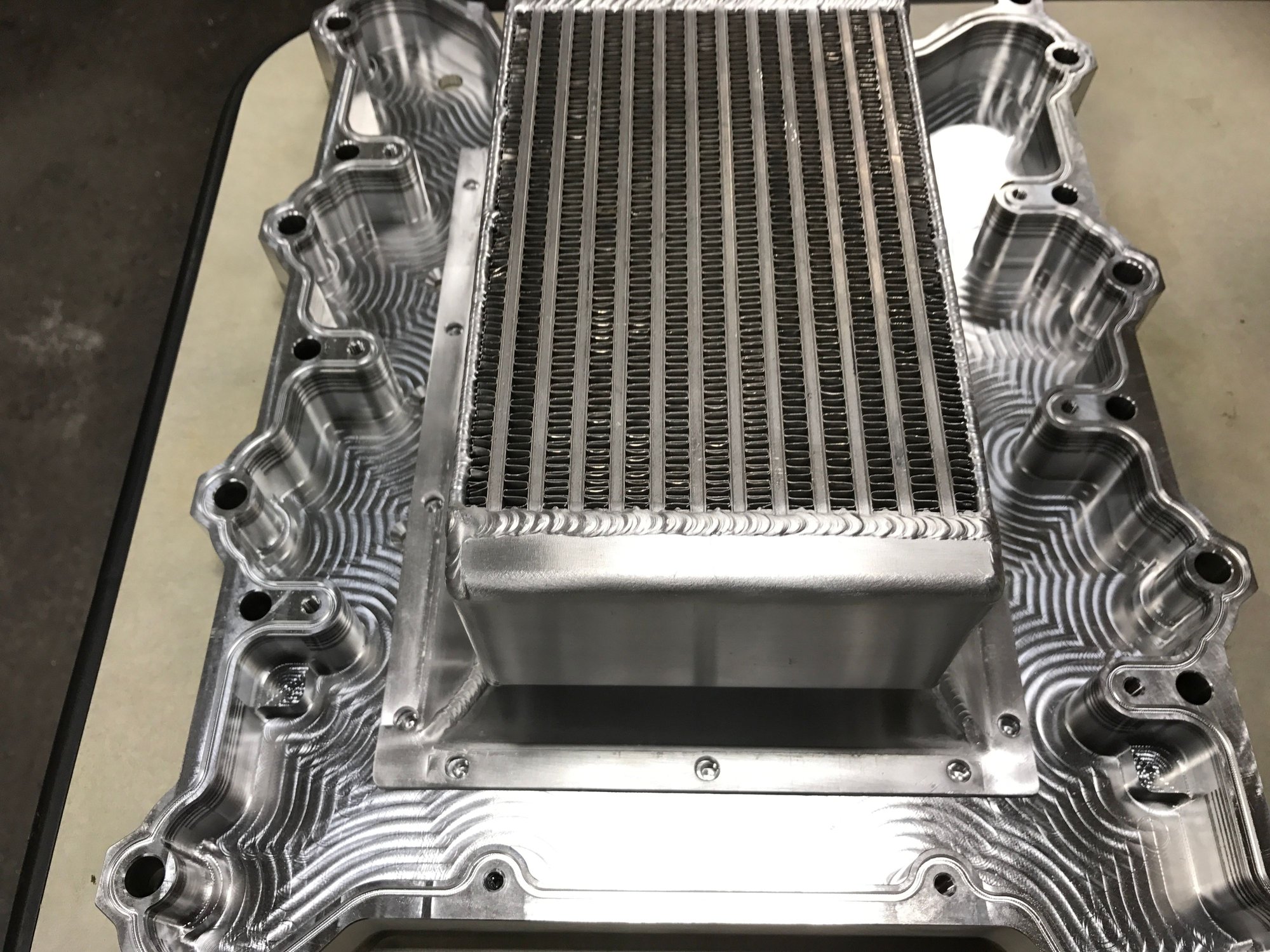
Prototype intercooler is in. I dropped by the shop to make sure the flange lined up.... everything is looking good. All the second sides are machined, but waiting in line to get the last rear face machined for the coolant and vacuum ports - because of the height of the part when standing up to do the boring, the shop only has two machines capable of this operation, and they are booked up this week.
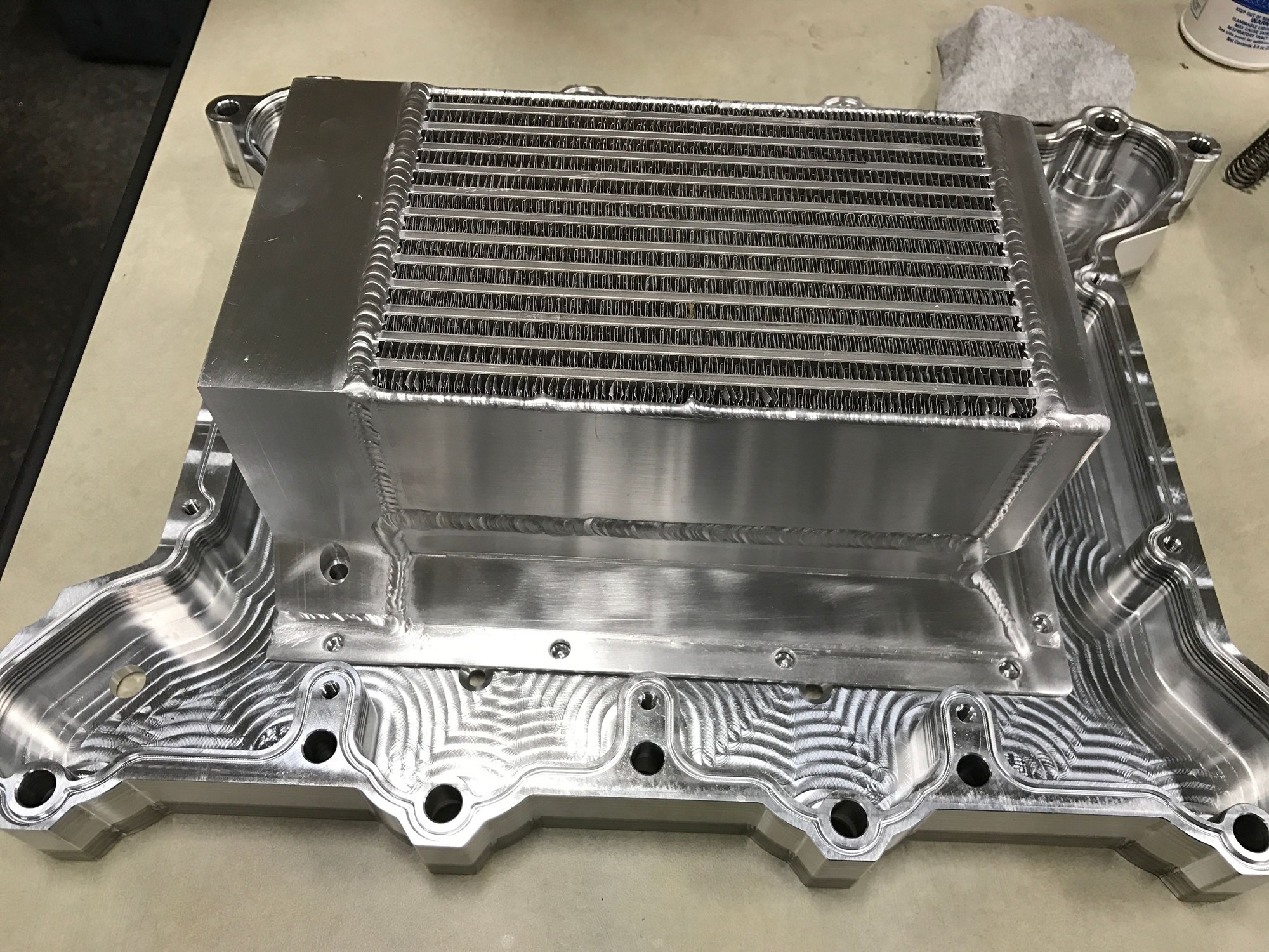
The rear tank is that the machined part I have shown in the past. The other flanges and front tank are fabricated by Bell. It is the absolute largest core that will fit in a 928 valley.
I did get to borrow the "scrap" part from the setup. It is dimensionally accurate in every way except the blower discharge port that was accidentally machined with a 1" offset for when they were testing the thread milling. We are going to use this part as a weld fixture and to setup/test the coolant port boring before the production parts. However, since we have a delay in the machine schedule, I am using it this week to assemble a mock finished manifold to double check the drive bracket and get that into machining next week too.
Looks like we should have finished manifolds and belt drive systems by the end of December.
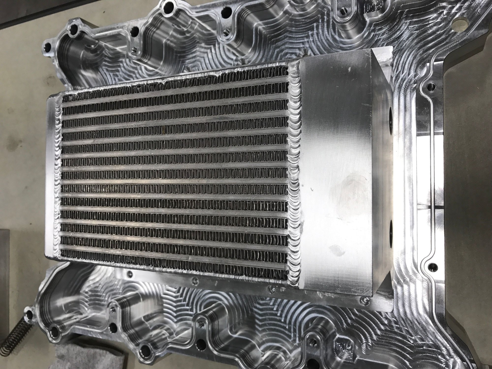
Its a big boy for sure. Wish there was a longer length standard core, but that is the biggest I can get in low quantity... but it is coming from the best manufacturer here in the States. Any narrower, and its significantly narrower than the discharge outlet of the 2.6L HPS (I even had to cheat a smidge to do the inverse mounting and there is a 10deg taper on the inlet of the manifold). Any wider and there is not a large enough passage between the core and the valley pan. Its "good" for 550HP worth of air, but will take the occasional blast higher if we ever dare turn up the pressure that far.
Lines and pumps are good for around 4.75GPM with the various restrictions in the system, so it should be fairly effective.
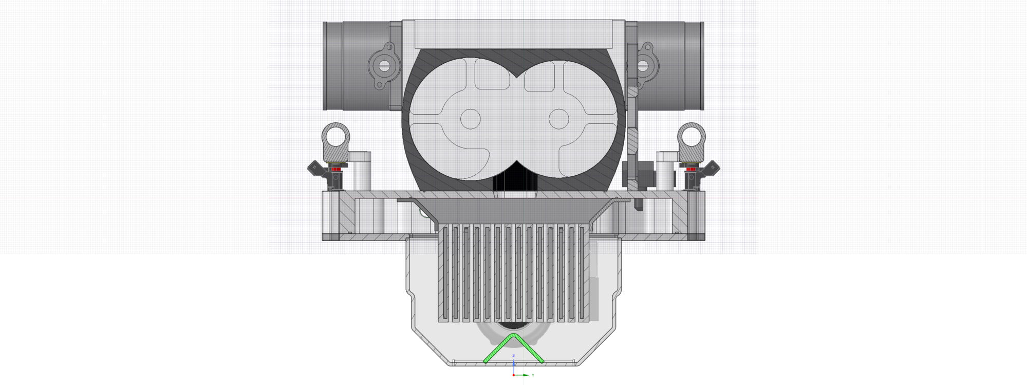
Its a slow news week. Hoping to get finished manifolds back this week. I did finally get all the hardware to assemble a manifold, so will be doing that this evening. Here is the updated valley pan designed with more clearance for block casting ribs.
You can see how large this intercooler is in relation to the pan. You just cant put a larger one in there.
Its the solenoid valve for the bypass valve. Instead of running multiple pulley sizes, this kit used an active boost controller so there is gobs of power down low where you want it.
The solenoid is plumbed as such: NO Port (normally open) goes to the vacuum reservoir (constant source of vacuum) NC Port (normally closed) goes the boost reference of the lower manifold COM Port (common or output) goes to the bypass valve
Thus, the valve will always be open (allowing the supercharger to freewheel) unless commanded to close and build boost by the controller. When the solenoid valve is engaged, it routes lower manifold pressure to the bypass valve, forcing the valve shut for a leak-free seal (there is a huge boost leak on most standard butterfly bypass valves). When the conditions for boost are not met, the controller de-energizes the solenoid, and it instantly sees full vacuum from the reservoir (despite whatever boost conditions may exist in the lower intake manifold) and the bypass valve will open immediately. Thus the single bypass valve can be used for both the intended cruise bypass function, and as a boost control/limiting device.
This allows full table boost control, including per/gear profiles and launch control. By sizing the supercharger pulley ratio to meet the superchargers upper end rpm requirements with the 928 redline, and instead bleeding off the excess pressure through this new bypass valve topology, we end up with a supercharger install that give the absolute highest amount of low-end and mid-range power with very little cost in upper-end performance (since we are "dumping" a good portion of the top end boost for safety reasons). The power delivery will be absolutely linear throughout the entire rpm range.
This boost control system will be a separate product I will sell for those who already have a twinscrew supercharger kit, and want to go to a small pulley and maximize their supercharger output as well.
I know we've talked about the following question before, but I never really understood how the bypass valve works with a twin-screw compressor.
A twin-screw compressor does work in two ways. First, it compresses the air internally. Second, it pushes the compressed air out of the compressor against the outlet pressure.
I don't understand how a twin-screw compressor can ever "free-wheel" as long as inlet has pressure, even if it's outputting to free air. The twin-screw compressor has an internal compression ratio and it'll do significant work regardless of outlet pressure, as long as there's significant inlet pressure. Furthermore, it will do additional work if it will be pushing the compressed air against the atmospheric pressure (assuming the manifold is vented to free air). The bypass valve like that in the drawing doesn't reduce the inlet pressure, so how can it reduce the work done to compress the air?
Furthermore, if I close the throttle (upstream of the compressor), the engine will immediately pull a large vacuum to the compressor outlet and the compressor inlet will pull a vacuum between the compressor inlet and the throttle. Even without a bypass valve of any kind, now the compressor _is_ in a sense freewheeling in a vacuum and doing relatively little work.
To me, based on my limited understanding, the bypass valve arrangements that make a lot of sense with a roots blower don't really make sense with a twin-screw compressor.
I'm also uncertain about why the engine vs. screw compressor would be non-linear in volumetric efficiency in a different way as a function of rpm. As long as the compressor inlet is large enough, it basically compresses air mass fairly linearly in rpm. The engine has a little bit more rpm dependency when normally aspirated, but with the extremely short runners and standard cams the VE curve feeding from constant pressure would be fairly flat.
Importantly, though, consider what happens when you connect the two in a series. With a twin-screw compressor that is about linear in rpm, the cylinder filling will be approximately independent of the intake manifold boost. The intake manifold boost will simply be a measure of restriction of the engine and will not impact the cylinder filling. Everything that the compressor outputs has to go thru the engine.
If the temperature stays in control, I don't see any obvious need to control the boost in any way. The WOT cylinder filling is about the same at all rpms, and there's no need to lower the boost for knock reasons, for example.
I'd appreciate if someone could educate me on this topic.
Originally Posted by hans14914
Its the solenoid valve for the bypass valve. Instead of running multiple pulley sizes, this kit used an active boost controller so there is gobs of power down low where you want it.
The solenoid is plumbed as such: NO Port (normally open) goes to the vacuum reservoir (constant source of vacuum) NC Port (normally closed) goes the boost reference of the lower manifold COM Port (common or output) goes to the bypass valve
Thus, the valve will always be open (allowing the supercharger to freewheel) unless commanded to close and build boost by the controller. When the solenoid valve is engaged, it routes lower manifold pressure to the bypass valve, forcing the valve shut for a leak-free seal (there is a huge boost leak on most standard butterfly bypass valves). When the conditions for boost are not met, the controller de-energizes the solenoid, and it instantly sees full vacuum from the reservoir (despite whatever boost conditions may exist in the lower intake manifold) and the bypass valve will open immediately. Thus the single bypass valve can be used for both the intended cruise bypass function, and as a boost control/limiting device.
This allows full table boost control, including per/gear profiles and launch control. By sizing the supercharger pulley ratio to meet the superchargers upper end rpm requirements with the 928 redline, and instead bleeding off the excess pressure through this new bypass valve topology, we end up with a supercharger install that give the absolute highest amount of low-end and mid-range power with very little cost in upper-end performance (since we are "dumping" a good portion of the top end boost for safety reasons). The power delivery will be absolutely linear throughout the entire rpm range.
This boost control system will be a separate product I will sell for those who already have a twinscrew supercharger kit, and want to go to a small pulley and maximize their supercharger output as well.
I can do my best to explain, but its tough to beat the excellent writings of Corky Bell who authored a complete book on the subject (its a companion to Maximum Boost, which I am sure you have read). I can highly recommend the read, and having a copy on your shelf, just as a handy reference for equations.
As you note, the twinscrew compressor is an air-pump which has an internal compression ratio. The amount of work it does is increased over a simple roots style blower by the tight intermeshing screws which yield the internal compression ratio. This tight fit insures that no air that enters the supercharger can revert back through the screw/lobes.
This pump is directly coupled to the crank (unless the belt slips) so will pump a given amount of air linear to the rpm of the drive. In my specific application with a 2.6L supercharger, even at a 1:1 ratio, compressor is capable (in theory) of pushing more air into the engine that it would consume on its own. This is of course limited by the amount of air allowed into the system by the throttles.
So, in an idle or cruise condition, where there is very limited amount of airflow past the throttle, the supercharger is fighting for air to compress which creates a number of issues, from temperature rise to bind on the throttle shafts. Additionally the discharge may be more air than the engine can consume given the valve opening duration.
The bypass valve works to help equalize the pressure at the inlet of the supercharger (after the throttle) and the discharge (before the intake valves). It allows the supercharger to pump the unconsumed air back through itself. It is not a true freewheel, as there are still losses through the bearings and the nominal internal compression, but when it is not pushing against the restriction of unopened valves or filling a cylinder, this amount of energy consumption is relatively nominal.
With the bypass-valve closed (or in system without a bypass), the only place the compressed air can travel is through the engine (or past stem seals and rings). Using the bypass valve as a boost limiting device is beneficial in this instance because it removed these issues but also keeps the supercharger operating at its maximum efficiency the second the bypass is closed.
That may not be helpful, which is why I pointed to the expert at the beginning of the post.
I can do my best to explain, but its tough to beat the excellent writings of Corky Bell who authored a complete book on the subject (its a companion to Maximum Boost, which I am sure you have read). I can highly recommend the read, and having a copy on your shelf, just as a handy reference for equations.
I've read a bunch of books on the topic, including Supercharged! and I haven't ever found a satisfactory thermodynamics explanation of external bypass valves for twin-screw internal compressors. Some people have written about supercharger oiling issues, but those are out of the scope of the thermodynamics explanations.
Originally Posted by hans14914
As you note, the twinscrew compressor is an air-pump which has an internal compression ratio. The amount of work it does is increased over a simple roots style blower by the tight intermeshing screws which yield the internal compression ratio. This tight fit insures that no air that enters the supercharger can revert back through the screw/lobes.
This pump is directly coupled to the crank (unless the belt slips) so will pump a given amount of air linear to the rpm of the drive. In my specific application with a 2.6L supercharger, even at a 1:1 ratio, compressor is capable (in theory) of pushing more air into the engine that it would consume on its own. This is of course limited by the amount of air allowed into the system by the throttles.
Makes sense so far.
Originally Posted by hans14914
So, in an idle or cruise condition, where there is very limited amount of airflow past the throttle, the supercharger is fighting for air to compress which creates a number of issues, from temperature rise to bind on the throttle shafts. Additionally the discharge may be more air than the engine can consume given the valve opening duration.
In idle or cruise conditions, the twin screw is not really fighting anything, because the inlet density and pressure are very low and outlet density and pressure are also very low. There's very little work being done either the compression operation or the pushing operation. The twin screw is basically free-wheeling, so I don't understand how it could be heating anything. Furthermore, I don't really understand how recirculating the air would do anything else but increase the work done and turned into heat.
Originally Posted by hans14914
The bypass valve works to help equalize the pressure at the inlet of the supercharger (after the throttle) and the discharge (before the intake valves). It allows the supercharger to pump the unconsumed air back through itself. It is not a true freewheel, as there are still losses through the bearings and the nominal internal compression, but when it is not pushing against the restriction of unopened valves or filling a cylinder, this amount of energy consumption is relatively nominal.
If you equalize the inlet and outlet pressure of a twinscrew compressor, you'll get a popping sound that is potential energy turning to sound and heat. If you "freewheel" an uninstalled compressor, you'll hear that. The twin screw supercharger is _in my opinion_ running close to the highest efficiency when the pressure ratio between outlet and inlet matches the internal compression ratio of the twin screw compressor. It seems to me that equalizing the pressure between inlet and outlet is the last thing you want to do from efficiency perspective.
Originally Posted by hans14914
With the bypass-valve closed (or in system without a bypass), the only place the compressed air can travel is through the engine (or past stem seals and rings). Using the bypass valve as a boost limiting device is beneficial in this instance because it removed these issues but also keeps the supercharger operating at its maximum efficiency the second the bypass is closed.
The engine is going to need certain amount of air mass to run at cruise. That's about the same as with a normally aspirated engine. The throttle position is used to limit the mass air flow to that amount. The compressor outlet will still be at vacuum (below atmospheric) conditions at cruise, so if anything outside air is trying to get into the intake port and not the other way around.


 11-25-2016, 01:18 PM