When you click on links to various merchants on this site and make a purchase, this can result in this site earning a commission. Affiliate programs and affiliations include, but are not limited to, the eBay Partner Network.
Does everyone see on that second set of very clear graphs, that with the L/D curve for no gurney vs gurney starts out with for the same lift, GF has MUCH more drag , until you get near stall? in no place does the GF produce any less drag, ever UNTIL, you reach stall. then the GF does its magic.
Mark, you had me at hello!
Seriously though, the essence of what you are saying is that for any amount of downforce that a Gurney flap can add, it is more efficient to increase the angle of the wing to get that same increase in downforce.
__________________
Larry Herman
2016 Ford Transit Connect Titanium LWB
2018 Tesla Model 3 - Electricity can be fun!
Retired Club Racer & National PCA Instructor Past Flames:
1994 RS America Club Racer
2004 GT3 Track Car
1984 911 Carrera Club Racer
1974 914/4 2.0 Track Car
CLICK HERE to see some of my ancient racing videos.
Seriously though, the essence of what you are saying is that for any amount of downforce that a Gurney flap can add, it is more efficient to increase the angle of the wing to get that same increase in downforce.
Of course you would get this all at first sight!
Yes, that is the essence.
The ONLY "what if " is that all wings are at near max lift even set at 0 angle of incidence. (as the idea was suggested by AOA coming off the roof being greater than 8 degrees). But , what if its 15 degrees?
well, when a wing is maxed out, it cant make any more lift. in my tests with actual cars, on actual roads , at varied speeds, I was able to set my wing at 3-8 and then 12 degrees and all three settings gave greatly different and higher downforce values. that is proof that my cup car wing, at its moderately raised position ,is not at a max level. it might be at 12 degrees, and if so, if I wanted to have even more downforce, I would back the wing down to about 10 degrees and put on a gurney flap for more downforce and reasonable drag values.
it seems that the gurney flap is basically a way to add 7 degrees of wing inclination without adding wing inclination, and add to the downforce capabilities of a given wing after it has reached its max potential.
I enjoy these discussions - when they stay civil. A number of items to consider re: your base data:
Your data sources show a Reynolds number of either 110,000 (about 12 mph) or 1,950,000 (about 220 mph). Profiles behave very differently in different conditions - this is why there are different profiles - so this should be considered.
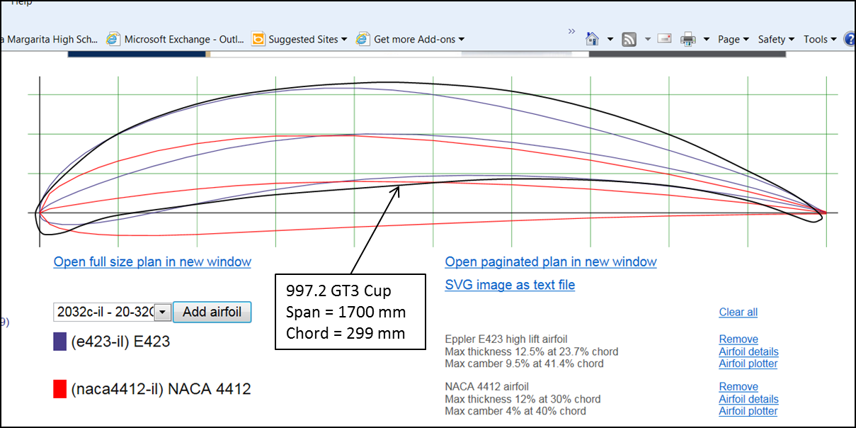
The Porsche Cup wing is simlar to an Eppler 423 profile (not the same, but similar). This is a high-lift, mid-speed wing with great L/D and soft stall characteristics - which seems perfect for our use. However, it behaves quite differently at varying Re numbers and turbulence conditions.
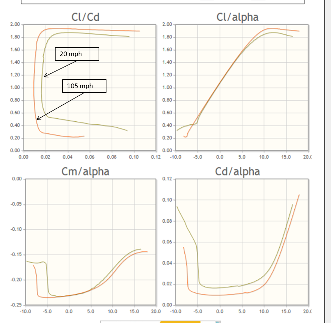
The first screen grab shows foil plots for the E423 at different Re numbers - Re 200,000 (about 20 mph) and Re 1,000,000 (about 105 mph). While the Cl is similar for varying AoA, the Cd is very different, with the e423 displaying a much lower Cd at the higher Re. The Cl/Cd is near 2x at 105 mph vs. 20 mph.
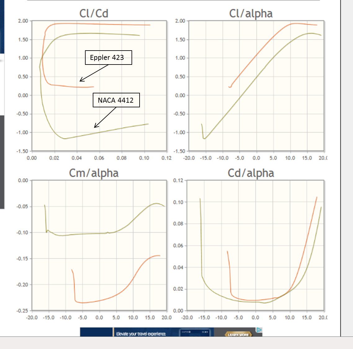
Next, Your data uses a NACA 4412 wing - this is a very different profile to that of the Eppler 423 with quite different performance characteristics - the E423 has better L/D performance in the window used on a race car. Please see the second and thrid screen grabs.
I am not making an argument that your GF data is invalid for the conditions your present, only that the actual profile, peformance, and conditions of our race car wings is very different and may result in a different outcome. The Mantis wind tunnel test should be telling.
An aquaintence of mine is a former F1 aero engineer and he absolutely insists that a GF improves efficiency at modest AoA in turbulent conditions on a race car - and as an added bonus improves stability and efficiency in crosswinds. However, the GF should be no more than 3% of chord, any more than that reduces efficeincy. FWIW, IMSA and others mandate GF height to drive Balance of Peformance among cars, not improve performance of the wing.
For those of you running the Crawford wing, it is / is similar to the LNV109A wing and very different in profile and peformance when compared to the Eppler 423.
It's important to note that there are three separate effects that a GF have and each is used differently by different applications, you can't isolate one without considering the others to make the assertion that its better to just crank up the wing.
1. A GF acts to change the effective chord of the wing, increasing camber and lift while increasing drag. A dumbed down wing flap. This is the mode that is being discussed in isolation in the charts. BUT as was mentioned above this is also speed dependent as well as higher angles of attack the differences in drag moderate. Wings on cars are usually operating in a very high angle of attack (and high lift) relative to the airflow over the car. Just look to the RSR wing where AOA is attenuated across the width of the wing to account for the directional airflow over the car.
2. A GF will lower the stall speed of the wing and increase the angle of attack before stall. On all the charts the sudden drop of the lift curves and jump in drag announce the stall of the wing. A stalled wing produces very little lift but a massive amount of drag. A cup wing runs much closer to stall angle than you would think and at an angle that is much closer to 15 degrees or better (courtesy of Procoach and Brumos):
3. A GF will improve the performance of a clean airfoil with little to no drag increase by creating trailing edge rolling vortext which creates a cleaner laminar flow between the top and bottom surfaces of the wing. These are very short (2-3%) GF that are often overlooked, sometimes they are just a small bead or fold on the end of the wing or small lip molded into the trailing edge, these are GF all the same. Every experiment, report, scientific analysis that all these charts come from mention this effect and conclude with its benefit.
4. A GF will improve the performance of a delta (swept back) wing. Why do we care? Most of the time we need the downforce is in a turn. Typically in a corner at max grip you need up to 10 deg of slip angle to get the tire to work and not to mention you are turning the car in the corner relative to the airflow. Net result is an improvement in the wing perormance and better downforce where you need it.
If you want to say that given the posted chart the Cd and Cl indicate that for that profile, at that speed, at that AOA the numbers in the charts bear out that more AOA creates less drag than a GF I will agree. But without all the other considerations it is pointless and to leap to the conclusion that its smarter to just crank in more wing I have to disagree.
2. A GF will lower the stall speed of the wing and increase the angle of attack before stall. On all the charts the sudden drop of the lift curves and jump in drag announce the stall of the wing. A stalled wing produces very little lift but a massive amount of drag.
Ok, I'm officially confused. This makes sense, but then why in F1 last year were they creating vortexes to stall the rear wing to reduce drag on the straight?
What the F duct was doing was selectively feeding pressurized air into the zone behind the wing effectivly filling the void that causes the majority of the drag of the wing and significantly reducing the efficiency of the wing, "stalling" it, eliminating downforce and allowing more top speed. Basically turning the wing on and off.
I enjoy these discussions - when they stay civil. A number of items to consider re: your base data:
Your data sources show a Reynolds number of either 110,000 (about 12 mph) or 1,950,000 (about 220 mph). Profiles behave very differently in different conditions - this is why there are different profiles - so this should be considered.
The Porsche Cup wing is simlar to an Eppler 423 profile (not the same, but similar). This is a high-lift, mid-speed wing with great L/D and soft stall characteristics - which seems perfect for our use. However, it behaves quite differently at varying Re numbers and turbulence conditions.
The first screen grab shows foil plots for the E423 at different Re numbers - Re 200,000 (about 20 mph) and Re 1,000,000 (about 105 mph). While the Cl is similar for varying AoA, the Cd is very different, with the e423 displaying a much lower Cd at the higher Re. The Cl/Cd is near 2x at 105 mph vs. 20 mph.
Next, Your data uses a NACA 4412 wing - this is a very different profile to that of the Eppler 423 with quite different performance characteristics - the E423 has better L/D performance in the window used on a race car. Please see the second and thrid screen grabs.
I am not making an argument that your GF data is invalid for the conditions your present, only that the actual profile, peformance, and conditions of our race car wings is very different and may result in a different outcome. The Mantis wind tunnel test should be telling.
An aquaintence of mine is a former F1 aero engineer and he absolutely insists that a GF improves efficiency at modest AoA in turbulent conditions on a race car - and as an added bonus improves stability and
efficiency in crosswinds. However, the GF should be no more than 3% of chord, any more than that reduces efficeincy. FWIW, IMSA and others mandate GF height to drive Balance of Peformance among cars, not improve performance of the wing.
For those of you running the Crawford wing, it is / is similar to the LNV109A wing and very different in profile and peformance when compared to the Eppler 423.
Cheers,
yes these discussions are good. Enjoy the debate and love them to stay civil.
I haven't dealt with Re in a long time, so a little rusty over the effects.... generally, it effects Coefficient of drag but not coefficient of lift. I forgot why that is, but it seems to be true and shown by your graphs.
keep in mind that MPH value in the Re is valuable to determine some key characteristics. the size of the wing is VERY important, as even if it is at 20mph or in the case of the clark T wing, 40mph, (as shown by the graph which is similar to cup car and 4412 wing) because the model size is very small, the results of lift and drag will be similar to other proportionate sizes.....and much higher speeds. that's why they use Re numbers to approx. values when the actual size is different at higher speeds. this wing would act the same and have the same values, at 80mph, if double the size for example.
Your information doesn't change the argument that GFs do NOT improve efficiency vs a wing with out it. I don't know if that is an actual cup car wing, but I have an older GT3cup car wing (2005-9ish) and its more like a NACA 4412. ( Can take a picture of the air foil shape if needed)
Either way, what you get with a higher lift air foil is more effectiveness, not efficiency. in fact, they are less efficient. What you really want to find or plot, is the lift to drag ratios. Again, I maintain at low wing angles and up to max lift capabilities of any of the wings discussed here, drag will ALWAYS be higher with the wing that incorporates the gurney flap. nothing you provided disputes that. what it does show, is that the max lift of the higher lift wing, will happen at a lower AoA, which is expected.
Your friend that is a x-F1 engineer, might know much, but when it comes to this kind of analysis, if he hasn't spent much time in the wind tunnel, he is using the type of information we have here, and many copy others in the field as well. (in practice and thought) The 3 papers , all comparing GF vs no GF (gurney flap, not girl friend ) , show that the ONLY thing that the gurney flap does, is extend the angle use of a given wing, and all 3 studies used grossly different Reynolds numbered wings . (High lift, low lift, and thin wing high lift at different speeds) beyond stall of a non-GF equipped wing.
However, I will say, when you get into high left wings, you can see that 0 AoA is a relatively high left setting. in which case, If its max level of lift is happening at 10 degrees. it would be prudent to use a GF If you plan on using more Downforce by making a change to a higher AOA. However, even at max downforce settings of that wing, its going to produce less drag without a GF.
Edit: in looking at the graphs more closely.... I see the 2nd and 3rd screen shots. the 3rd is what you are referring too. you can see, the 4412 has an optimum range and allows for more flexibility , should you not want as much rear downforce. as you can see, even at 0, the E423 produces much higher downforce.. forget about looking at the range below 0 lift. I don't think anyone would use the wing below that setting, so, from 0 to a Cl of 2, you can see the contrast of the two wings. the 4412 is more efficient in the lower downforce ranges, and the E423 gives more lift capabilities.
the point here is that putting a gurney flap on , even at 3% , doesn't make the wing more efficient... in fact, in all cases below max lift values, it will make more drag. (less efficient than a bare wing)
The net net of your grapsh is that up to 1.0 Cl, the NACA4412 is a more efficient wing, and above it, the E423 is better past 1.0 and beyond the max capability of 1.5 and onward to its max of over 2.0 Cl.
An interesting question would be, would a GF on the 4412 be more efficient than the E423 and produce the same lift. (at less drag).
what is clear is that the 4412 with 4% gurney flap would produce more downforce.... whats up with your 3 screen shot graphs drag scale.... that cant be right.... .02 Cd vs 2.0 Cl.... is 100:1.... is that axis off
by a decimal?
Last edited by mark kibort; 11-01-2014 at 06:42 PM.
It's important to note that there are three separate effects that a GF have and each is used differently by different applications, you can't isolate one without considering the others to make the assertion that its better to just crank up the wing.
1. A GF acts to change the effective chord of the wing, increasing camber and lift while increasing drag. A dumbed down wing flap. This is the mode that is being discussed in isolation in the charts. BUT as was mentioned above this is also speed dependent as well as higher angles of attack the differences in drag moderate. Wings on cars are usually operating in a very high angle of attack (and high lift) relative to the airflow over the car. Just look to the RSR wing where AOA is attenuated across the width of the wing to account for the directional airflow over the car.
2. A GF will lower the stall speed of the wing and increase the angle of attack before stall. On all the charts the sudden drop of the lift curves and jump in drag announce the stall of the wing. A stalled wing produces very little lift but a massive amount of drag. A cup wing runs much closer to stall angle than you would think and at an angle that is much closer to 15 degrees or better (courtesy of Procoach and Brumos):
3. A GF will improve the performance of a clean airfoil with little to no drag increase by creating trailing edge rolling vortext which creates a cleaner laminar flow between the top and bottom surfaces of the wing. These are very short (2-3%) GF that are often overlooked, sometimes they are just a small bead or fold on the end of the wing or small lip molded into the trailing edge, these are GF all the same. Every experiment, report, scientific analysis that all these charts come from mention this effect and conclude with its benefit.
4. A GF will improve the performance of a delta (swept back) wing. Why do we care? Most of the time we need the downforce is in a turn. Typically in a corner at max grip you need up to 10 deg of slip angle to get the tire to work and not to mention you are turning the car in the corner relative to the airflow. Net result is an improvement in the wing perormance and better downforce where you need it.
If you want to say that given the posted chart the Cd and Cl indicate that for that profile, at that speed, at that AOA the numbers in the charts bear out that more AOA creates less drag than a GF I will agree. But without all the other considerations it is pointless and to leap to the conclusion that its smarter to just crank in more wing I have to disagree.
PS: GF does not = Girl Friend
Richard, you are making my point and also bringing up some good points of your own.. ...... as I mentioned earlier, the only caveat to not using a GF, is if the wing is beyond, not AT, but beyond stall. the picture of the air stream hitting the GT3 wing, is a little sckewed. a few frames earlier to see the air stream hitting the center of the wing would be more appropriate for analysis.
I totally agree, the shape of the car is critical... in fact, off the ferarri, there is less deflection. But , deflection and angle change none the less. Is it 15 degrees? (my roofline is exactly 16 degrees on the back side, the air flow will be something much less than this) probably not, but certainly near 10.
Now, in a turn, the wing becomes a swepted wing. its effect is the same as if the wing had a longer cord..... hmmmm now what does that do? it actually raises the stall value, so it works against your argument but makes a very important point. The downforce is needed in the braking zone, and during the turn and turn in. All different speeds and all different wing orientations (relative wind and angle across the wing.... or the "swept wing" effect)
Now, a few comments on your other points.
1. I agree
2. you have to define stall. yes, as you approach stall, the drag is contiunieing to increase as lift actually starts to fall or sometimes even stays flat as the AoA is increased. lets focus on what we care about . at max lift, the drag is at a point where we don't want it to increase. we add more wing angle and the drag goes up and the lift might not increase. this is bad. no more lift, but more drag with more wing angle. its not stalled, but the drag is getting worse for more angle. SO, at this point, we either add a GF or deal with the max angle and not go any further.
3. I disagree based on the data. all GF additions have increased C/D values. the only time they have improved efficiency at high lift demands of the wing.... beyond what was available with a clean wing.
all the reports and studies have mentioned that these small GF additions have added lift, with "not much, or negligible amounts of drag added. "not much is relative" for our uses, that amount was shown to be near 20% more drag even in the lowest GF height percentages . if you disagree, show me a chart where this is not true. remembrer we are comparing same lift vs drag values, regardless of wing angle vs a clean wing. look at the data, in all 3 of the detailed studies.... Drag is increased up to 2x (200%) by the use of a 2-3% GF. so I would like to understand how you think there is "no drag increase". in fact there is always more drag... not so much more at near max lift, but still slightly more. If I was at near max lift with my wing, I certainly would back the wing off angle and use a GF.
4. again, as I mentioned, the swepted wing "effect" actually makes the wing somewhat more effective by presenting a different cord length to the oncoming air flow. (at the cost of less wing width) . its something to think about .... don't think the GF would have any different effect than it already is having.
below.... drag vs lift curves for 23012 type wing and 4412 (4412 is very close to older cup car wing, like what I use)
Originally Posted by J richard
different application of "stall"
What the F duct was doing was selectively feeding pressurized air into the zone behind the wing effectivly filling the void that causes the majority of the drag of the wing and significantly reducing the efficiency of the wing, "stalling" it, eliminating downforce and allowing more top speed. Basically turning the wing on and off.
Yep.. like removing the end plates.... the vortexes are allowed to come around and neutralize the downforce at the wing ends reducing drag due to lift, also, less rolling friction due to less force on the tires.
Here is some slow motion video of what the angle really is on the Porsche to the wing. don't forget that the video of the brumos wing, shows a lot of turbulence off the roofline that really doesn't equate to a effective and equivilant, true AoA to the wing...... it looks like I said, about 10 degrees.
In the case of the 458, its clear to see that when Mike lost a gurney flap when wing set at "0", it would been wise to incline the wing 6-7 degrees and send him back out for the same downforce and 50% less drag. Again, there is no real argument to not doing removing the gurney flap in a flat wing set up, other than "everyone else has one".
That is of course if you wanted to save (or gain) 8hp!
Also......Krocodil!!!! thanks for showing and doing the research on the cup car wing... I just pulled off my end plates and YEP, that's the shape of my cup car wing too!.... So, I better not be at an AOL of above 10-12 or its better to put that GF back on and back the wing down to 4 degrees from its angle of incidence of 7.
sounds like I need to get the spring scale out and do some 120mph runs with the GF...... or , to save drag, if im at max now and its working, back the wing off to the point where it doesn't lose any downforce, and just gives lower drag. (i.e. looks as thought max lift if found at 10-12 degrees.)
EDIT: after reviewing the closest wing to the E423 cup car wing, it actually looks like if im at 7 degrees and have a AOL shift of another 7 degrees, being at 14 degrees could be over the max lift enough to produce a lot more drag. in fact, from the graphs, anything over 10 degrees AoA gets slammed with drag......
I might be better off, if im over the AOL max lift, by even 2 degrees, it might be better to drop my Angle of incident to 2-3 degrees (down 5 degrees) and put back on the gurney flap. (based NACA 23012 wing data)
that way, I still get 1.2 Cl and keep the drag near .18, but if im over the AoA limit of 12 degrees, by even 2 degrees, the lift is down to 1.1 Cl but the drag could be near .25 Cd. (50% more drag)
However, based on the actual cup car wing data, (E423) its even more critical than that. 10 degrees is the max Cl at near 1.8 Cl. so, being 14 or 15 degrees effective AOA, is way over max and drag goes up by near 3X.
in that case either drop the wing angle by near 5 degrees right now, (down to 2 degrees angle of incidence) or make it 0 and put on a gurney flap.
The theory and charts are great, but remember I still had tests that showed tremendous differences of downforce at 0 vs 7 degrees angle of incidence, indicating that the deflection angles might be lower than they appear.
That's why I like this kind of discussion.. you get to look at all sorts of information and make some choices to improve stuff. have to dig in and look a little closer at the possible numbers and take some measurements.
Last edited by mark kibort; 11-01-2014 at 09:34 PM.
Now, lets not confuse Reynolds numbers with speed as your graph pointers seem to infer Reynolds numbers are used to be able to look at same wing shapes with different scaling (velocity and size) and be able to determine many characteristics of the wing. values of 10^-5 vs 2x10^-5 doesn't equal a velocity comparison. Where did you get that from or can you explain what you mean?
I don't think I am confusing anything. The Re number is estimated by the speed, chord, and air density. So, back calculating from Re =200,000 with a 300mm chord and 68F air yields ~ 22 mph. Doing the same math for Re = 1,000,000 yields a speed of ~ 115 mph.
Using xfoil to build the data for the Eppler423 @ Re = 200,000 and Re = 1,000,000 @ Ncrit = 5 (turbulent) yields the plots posted earlier. These same calcs provided estimated Cl/Cd values. At R = 200,000 (~22 mph) the Cl/Cd = 84.3 and Re = 1,000,000 (~115 mph) the Cl/Cd = 145.2. The Cd shown in the xfoil data is the base Cd (Cd0) and not the Cd used to actually calculate drag. The total Cd is calcuated via the equation Cd = Cd0 + Cl^2 / ( pi * Ar * e).
When you look at the plots the Cl only varies with AoA while the Cd varies with AoA and speed. So, the Cl/Cd number varies with speed. So, while not linear, looking at a wing at different Re numbers does provide a performance at velocity comparison.
your information doesn't change the argument that GFs do NOT improve efficiency vs a wing with out it. I don't know if that is an actual cup car wing, but I have an older GT3cup car wing (2005-9ish) and its more like a NACA 4412. ( Can take a picture of the air foil shape if needed)
As I said in my post, I am not making an argument against your data, only that wings perform very differently based on profile and operating conditions. In fact, while the E423 is similar to the cup wing, it is not the same and is likely to perform a bit differently. The Cup wing has a bit softer camber profile that may be better in high AoA, but I don't know. If anyone knows the exact profile we can probably find the data.
Unfortunately much of the publically available data on GF is either done at higher speed (airplanes) or lower speed (formula SAE, etc.) with little/none on sports car wing, shape, and speed.
Originally Posted by mark kibort
Your friend that is a x-F1 engineer, might know much, but when it comes to this kind of analysis, if he hasn't spent much time in the wind tunnel, he is using the type of information we have here, and many copy others in the field as well. (in practice and thought)
I will not call him out by name (he doesn't deserve to get sucked into our amateur arguments), but will say that he has significant time in the wind tunnel and is one of the most experienced specialists in automotive drag reduction.
Hi, just adding a different pointy of view, you need to be in a windtunnel to really know and see what all this stuff we add on our cars actually does. Then chuck all the math out the window. After testing real cars and speeds of 60 to 140 mph, you can see what really happens. splitters and wing/wicker locations, shapes make a big difference.
I don't think I am confusing anything. The Re number is estimated by the speed, chord, and air density. So, back calculating from Re =200,000 with a 300mm chord and 68F air yields ~ 22 mph. Doing the same math for Re = 1,000,000 yields a speed of ~ 115 mph.
Using xfoil to build the data for the Eppler423 @ Re = 200,000 and Re = 1,000,000 @ Ncrit = 5 (turbulent) yields the plots posted earlier. These same calcs provided estimated Cl/Cd values. At R = 200,000 (~22 mph) the Cl/Cd = 84.3 and Re = 1,000,000 (~115 mph) the Cl/Cd = 145.2. The Cd shown in the xfoil data is the base Cd (Cd0) and not the Cd used to actually calculate drag. The total Cd is calcuated via the equation Cd = Cd0 + Cl^2 / ( pi * Ar * e).
When you look at the plots the Cl only varies with AoA while the Cd varies with AoA and speed. So, the Cl/Cd number varies with speed. So, while not linear, looking at a wing at different Re numbers does provide a performance at velocity comparison.
As I said in my post, I am not making an argument against your data, only that wings perform very differently based on profile and operating conditions. In fact, while the E423 is similar to the cup wing, it is not the same and is likely to perform a bit differently. The Cup wing has a bit softer camber profile that may be better in high AoA, but I don't know. If anyone knows the exact profile we can probably find the data.
Unfortunately much of the publically available data on GF is either done at higher speed (airplanes) or lower speed (formula SAE, etc.) with little/none on sports car wing, shape, and speed.
I will not call him out by name (he doesn't deserve to get sucked into our amateur arguments), but will say that he has significant time in the wind tunnel and is one of the most experienced specialists in automotive drag reduction.
Thanks for the reply. yes, in agreement with regards to Reynolds numbers. as I mentioned its been a long time. yes, velocitiy is a major component.
whats up with the drag values on the graphs. (your graphs from that handy site) it looks like they are off by a factor of 10. 2.0 Cl seems correct for our E423 wings (and yes, I concede that the cup car wing is very close to that shape). however, the drag for 2.0 shouldn't be in the range of .02, it should be more like .2, right...can you verify that??
all great information . its made me rethink my wing angle .... in fact, best case scenario, wings at 7 degrees and roof line deflection ,even turbulent, is 7 degrees, so that's 14 degrees. 4 degrees over max lift and, like I mentioned, 300% more drag than if I just backed the wing off 4 degrees OR, put the gurney on and put the wing at 0.
as far as the aero engineer, he knows this stuff then. but, at first glance many can ignore the cross over points, because rarely do they use the wing in a flat condition. however, if you look at mike's situation at RA and Sebring. If he was using a flat wing, there is no way with all the information posted so far that there is any indication that a gurney flap would be the lowest drag condition. even with our best information, it looks like it would come at a cost of about 50 to 100% more drag. at any significant inclination, sure, GFs would be the way to go, to get more downforce and insure you didn't get more drag with no more lift, as what happens with a clean wing going beyond max lift.
we cant really use stall, because stall is relative to something staying a float..... past max lift, doesn't necessarily mean "stall" it just means the drag is going up disproportional to lift.
Thanks for the info , again...... made me rethink and readjust my set up that might help with greater straightline speed.
I do think the E423 is very close to our cup car wings. .. after closer views of it, I think its a little more aggressive than the cup car wing. (more camber) but it makes your points very clearly! in fact, all we need to do is look at something between the E423 and the NACA4412, 90% toward the E423) and we have a great idea of what is really going on and the risks of more drag should we step over the AoAs shown.
Just measured my wing and it looked more like it was set at 9%, so with deflection of air flow, it might be as high as 16degrees. in that case, I was producing slightly less than max lift, at 400% more drag.
Can you check your drag numbers, there still looks as though there is a decimal point off. 100 to 150:1 L/D doesn't see possible with a cup car wing or the e423 wing. think about it, at 500lbs of downforce, that would be less than 3-5lbs of drag, and at 150mph, that would be only 1ft-lb of torque at the engine. (through the gear ratio of 3.2:1 , or 4th) I would say, drag would be in the 10 :1 or 20:1 range as with most wings. that site might have an error on it.
Anyway, thanks again. I figure if I was 4x the drag for the same downforce, I was pulling an extra , Hmmmmm 300 lbs of downforce at 120mph, so that's 30lbs of drag at 10:1 (normal lift/drag ratio......or 8ft-lbs of engine torque normally at 120mph... But if im at 400% more drag, that's more like 32ft-lbs of engine torque lost! that's a lot!!!
But do check out the drag values... they look way off on your simulator.


 10-31-2014, 12:11 AM