When you click on links to various merchants on this site and make a purchase, this can result in this site earning a commission. Affiliate programs and affiliations include, but are not limited to, the eBay Partner Network.
Hi , Just a few questions on Cam Timing.I been searching around a lot for the correct way to do this and havn't come up with a definitive way to do so. I'm going to have the P253 tool(if they ever send one that works!!) and the 9612 that comes with a kit. I was just going to follow the below steps. I have a 99 Boxster and doing the work w/ engine installed. Already completed IMS and RMS and have to replace solenoid in Bank 2. I don't however see the notch on the intake cam everyone's talking about, is this on the opposite side of where the 2 green plugs come out? I know which bank is at TDC by looking at the smaller arc on the exhaust cam that should be on the outside.(tool doesn't fit in otherwise) Any help would greatly be appreciated. Thanks Vin
1. lock motor to TDC
2. remove bank 1 oil scavenge pump
3. loosen sprocket bolts
4. install 9612 tool to rotate exhaust cam and align
5. tighten sprocket bolts
6. re-install scavenge pump
7. rotate engine 360 and lock crank
8.Repeat steps for bank 2
I'm not sure whether to lock the crank and move the cams OR line the cams up and move crank to TDC.I read moving cams is difficult due tension from valve springs.
Also read to remove 1 bolt at a time after cams are allocated and add locate.
Any help appreciated. V
Thanks anyway, but it doesn't actually give a description if you need to actually reset the timing...Adjust cams to crank or vice versa crank to cams?? BTW I'm waiting for my 3rd P253 Cam Tool....1st 2 didn't drop in...going with the 9216 tool see if it worked better. V
Thanks anyway, but it doesn't actually give a description if you need to actually reset the timing...Adjust cams to crank or vice versa crank to cams?? BTW I'm waiting for my 3rd P253 Cam Tool....1st 2 didn't drop in...going with the 9216 tool see if it worked better. V
Did you read the section "Checking Camshaft Timing"?
If the P253 tool didn't "drop in" that's not a bad tool but a sign the timing is off. The section below then directs you to another technical article:
With the new bearing installed in place, you are basically done with the installation. Be sure to reinstall / re-tighten your chain tensioners if you loosened them up, or removed them during the installation process. At this point, it's very important that you check your camshaft timing prior to reinstalling the transmission and starting the engine. Figure 128 and Figure 129 show how the timing chains are oriented and setup on the 5-chain (Boxster thru 2002, 996 Carrera thru 2001) and 3-chain motors (Boxster 2003 and later, 996 Carrera 2002 and later). Particularly with the 3-chain motors, you need to make sure that you check the exhaust camshaft for cylinders 1-3 (located to the right of the flywheel). This particular camshaft has the least amount of chain wrap and removing the chain tensioner to perform the replacement has the potential to loosen the chain and allow the timing to skip a tooth on the sprocket.
To check the timing simply take the crankshaft and rotate it 360 degrees from where you originally placed it when you installed the set screws (Figure 60). Then check the marks that you made on the camshafts (four marks on all four camshafts for the 3-chain motors, two marks on the exhaust camshafts for the 5-chain motors). If all of the marks line up perfectly (see Figure 136, Figure 137, and Figure 138), then you're golden, and you can continue with the process. If any of the marks are off, then there is the potential that the timing chain slipped off of the camshaft sprocket during the installation process. See Project 16 for more information on retiming the camshafts if this happens.
If you happen to have the P253 camshaft timing tool, you can use that to check the timing on the 5-chain engines. Simply place the engine at Top Dead Center (Figure 132), remove all four green caps on the camshafts, and install the tool on each side to check each pair of camshafts (Figure 135). If the tool fits, then the timing is perfect. If it doesn't fit, then you will have to retime the cams (see Pelican Technical Article: Camshaft Upgrade / Chain Tensioner Replacement). It's very good practice to check the timing on the 5-chain motors, but in reality, very few of these have problems, unless the instructions were not followed correctly. Still, I recommend checking the timing prior to reinstalling the transmission: it's cheap insurance.
When you're done, carefully rotate the engine a full 360 degrees and check the camshaft timing marks that you made before you started. If they all line up, then you're good to go. If they are off, then your timing chain skipped, and you need to re time your cams. See Project 16 for more details on this procedure.
After you're done checking the camshafts, install new camshaft end caps as shown in Figure 139, Figure 140 and Figure 141. Although I like to use a bit of sealant everywhere, these end caps don't tend to leak.
Also important to note, if you have the camshaft tools handy, you might want to check your camshaft timing *prior* to beginning the installation of the bearing. If the timing is slightly off and the bearing appears fine, then you might have some additional problems in your camshaft timing chain mechanism (slipping sprockets on the intermediate shafts, worn pads on the camshaft solenoid mechanisms, etc.). I would advise investigating these problems prior to pulling out the bearing.
At the time of this writing (June 2010), I'm working on developing some cheaper camshaft locking tools that will allow you to lock all of the camshafts on the engine. The two tools will work either on the 3-chain or 5-chain motors and will only cost about $20 (the factory tools cost about $200 each at this time). Stay tuned, and keep watching the Pelican site and this article for more details.
Yes....believe me I read everything. As for the tool I can drop it in when the crank is a few degrees after TDC which in turn lines up the grooves in the Exhaust cam BUT I can't bolt it to the engine case the bores don't line up....now this happens for both banks....just hard to believe both banks are out of time at the exact same place which leads me to believe it was the tool. AND I have the cam lock tool(the half size one that locks the exhaust and bolts to the engine) and that drops right in at TDC on both banks (another reason I'm thinking the tool is out) Spoke w/ SIR Tools and apparently they had a bad batch. What do you think?? Thanks V
Yes....believe me I read everything. As for the tool I can drop it in when the crank is a few degrees after TDC which in turn lines up the grooves in the Exhaust cam BUT I can't bolt it to the engine case the bores don't line up....now this happens for both banks....just hard to believe both banks are out of time at the exact same place which leads me to believe it was the tool. AND I have the cam lock tool(the half size one that locks the exhaust and bolts to the engine) and that drops right in at TDC on both banks (another reason I'm thinking the tool is out) Spoke w/ SIR Tools and apparently they had a bad batch. What do you think?? Thanks V
Return the 2 tools for credit and get a 3rd tool and see if the results are the same. If the results with the 3rd tool aren't the same then the first 2 tools were bad. If the 3rd tool delivers the same results you can try a 4th tool or...
Both banks can be out of time if the crankshaft to IMS chain timing is off.
I've never worked on the Boxster engine but I worked on a couple of US V8 engines and one Japanese SOHC engine and I took extra pains to ensure cam timing was correct. If it is not correct you probably won't get a 2nd chance to make it correct if you crank/run the engine. Well, at least not before you replace what was damaged from the cam timing being off.
Hmmm....so you're saying if the Crank to IMS let's say skipped a tooth it would throw both banks out equally. Getting worried... Well.... I picked the car up from the purchase and drove it home for 2hrs....seemed fine....I expected it to have more pick up but it's the 1st time I ever drove a Porsche let alone a Boxster. BUT Well like I said (I checked again today) I dropped the Cam lock tool in again(the half sized one for exhaust only) and it does drop in, I can bolt it up on both banks at TDC respectively. Tried the new tool and it wasn't working either, I lined it up to where the tool was saying it was aligned but when I eyeballed after removing the tool the exhaust cams were way off not near lining up with the crankcase seams. I don't know ....when I just use the the tool that actually fits but is not 'really' an alignment tool and then remove it and eyeball it ....it looks fine. I put the cam holding tool on today and pulled the Cam Cover to replace the solenoid. Next time I'm underneath I will try and see the colored links and indent to see if the cams are aligned on that bank....Exasperated!! Thanks for the reply. V
Well ..feel a little more confident. Removed my cams today and found timing was off between them as I suspected.(1 tooth on the exhaust).The chain wasn't set up correctly as well. Some pics of cams and badly worn ramps. Some questions.
How does the pic of the lifter look....looks good to me?
Torque specs for: solenoid to actuator ?
Actuator to Cam Housing ?
Cam Cover 9.5
Bearing Saddles 7.5
Sprocket 10 + 10% so 11.5 (I read it didn't do the math)
Is it necessary to use loctite on all the bolts? They seem to have a green coating on them. If so green wicking?
I imagine I should do the other bank considering the shape of rails on bank 2(also intake notch was not at 3 o'clock)
I tested the solenoid with 12v the pin was pushed out only about a 16th of an inch then it started smoking??? Had oil in it as well.
I see no pics of anything in your latest post.For the lifter the face that contacts the cam lobe wants to be free of any signs of wear. Use the other lifters as guides as to what the faces should look like. Ditto the cam lobes. The body of the lifter likewise wants to be free of any signs of metal to metal contact the aluminum bore into which the lifter fits wants to show no signs of metal to metal contact.
The "zero lash" adjuster can be removed from the lifter and it should when worked in oil stiffen up.
Be aware the chain guide plastic rails/ramps "wear" down to the point the chain rollers make contact with the plastic then essentially wear stops as the chain rolls/slides over the plastic on a film of oil. Thus the ramps/chain rails can look "worn" but are not. However, if you want to replace the ramps as a precaution that is entirely your call.
Can't help you with torque questions, or questions about the permissible timing variations, or question of the use of thread locking compound. I gave my set of Boxster factory manuals away so I no longer have this reference.
While I had a VarioCam solenoid replaced in my car (along with the VarioCam actuator the thing to which the small chain guides/rails are attached) I can't tell you what the behavior of a solenoid should be when fed 12V power directly. The solenoid only has to push open a hydraulic valve -- maybe in the form of a ball bearing in a round seat -- to activate the actuator. But I do not know how much force this requires nor does the solenoid require an oil bath to help keep it cool while it is active.
What you do not want to see is any sign of metal to metal contact at the cam lobe or at the lifter bucket top. At the lobe if you drag a fingernail across the lobe face anywhere around the lobe you should not feel anything. The same is true of the lifter bucket face. None of the lobes or the lifter face look bad to me but I'm not at the engine but you have the other lifter buckets and other lobes to go by. They ain't all bad and if one is bad it should stand out clearly from the rest by how it looks, how it feels.
Do not use a magnet to remove the lifter from the lifter bore. This can magnetize the lifter where the magnet touched it and this will then attract ferrous metal debris and this will result in accelerated lifter/lobe wear.
If you remove more than one lifter to not mix them up. The lifter should go back in the bore it came out of.
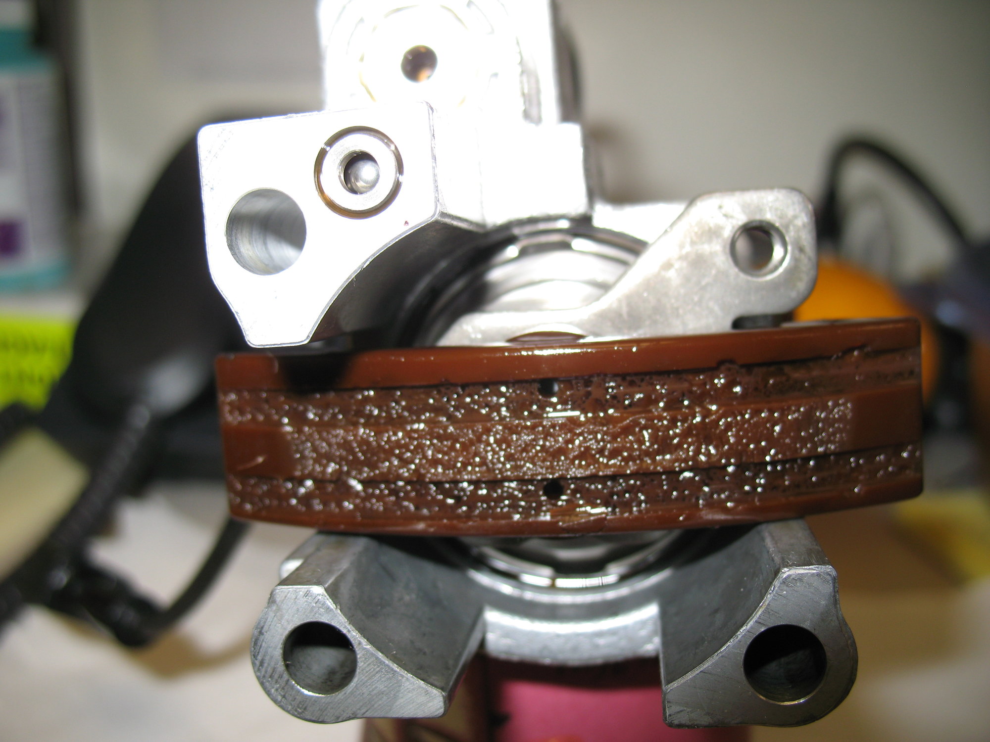
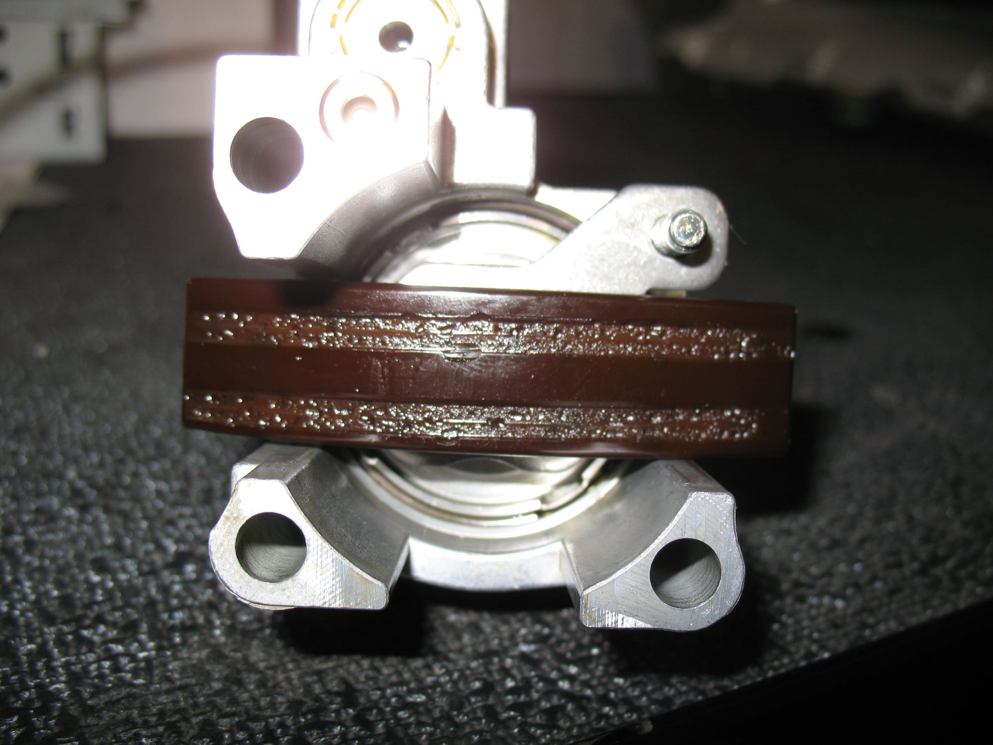
The plastic rail looks ok. But if you want to replace the rail "while you are there" that is up to you. The rail wore down until the surface area that was in contact with the center part of the chain reduced the pressure enough to bring any more wear to a halt. A new rail will have the two grooves into which the chain plates will run -- this to make sure the chain doesn't slide off to one side or the other -- and the area between the rails will look like the areas at either end of the pictured rail. As a new rail wears in this will show up as bits of plastic in the filter element or in the filter housing oil if you pour this out into a clean pan.
Attached is a pic of my Boxster's old actuator rail (with approx. 260K miles on it):
At the office I took a picture of a new Boxster lifter.
While it may not look like it the face is very blemish free. The thing has been in a plastic bag on my desk at the office for years.
(Years ago I bought a Boxster lifter to study how the lifter was constructed and how the zero lash mechanism worked and how it could possibly fail. More recently I bought a new lifter intended to be used in a VarioCam Plus engine. This lifter has has a low and high (normal) lift feature.)
Hey thanks for the reply. Funny the Boxster Factory Man.says to remove with magnet....I didn't though I just pulled them out n soaked them in oil and kept them in order(I think). What would happen if I reversed them Exhaust for intake??The new rails are perfectly smooth OEM no grooves!! The lobes and lifters are pretty smooth, I'm seeing some wear where the cams run on the bearings. Seems light ,,....can nearly feel it with my fingernail. Thanks again for your input. Vin
Hey thanks for the reply. Funny the Boxster Factory Man.says to remove with magnet....I didn't though I just pulled them out n soaked them in oil and kept them in order(I think). What would happen if I reversed them Exhaust for intake??The new rails are perfectly smooth OEM no grooves!! The lobes and lifters are pretty smooth, I'm seeing some wear where the cams run on the bearings. Seems light ,,....can nearly feel it with my fingernail. Thanks again for your input. Vin
The manual is translated from German and that direction use a magnet to remove the lifter reads like a translation error. Even if not I would not use a magnet.
You were smart to not use a magnet.
You should not mix up lifters and lobes. Once the engine has run in it is very important each lifter/lobe remain together. You can -- based on what I know the techs do at the factory's direction -- replace a lifter or lifters (even an entire bank of intake or exhaust lifters) and not replace the cam (provided of course the cam is in acceptable condition) or replace a cam and not have to replace the lifter or lifters (provided the lifter/lifters are in acceptable condition) -- but mixing up otherwise good lifters and lobes is ill advised. The lifter and lobe have developed surfaces that are paired with each other and different from the other lifter/lobe pair surfaces. To mix these up then requires a "break in" process be done again -- for both the lifter and cam lobe -- and this can lead to premature failure.
The cam bearing journals run in aluminum "bearings" that are formed by the bolting of the camshaft cover to the head. The bearings are in native metal. There are no inserts unlike the crankshaft main and rod bearings. There is no refurbishment of these available. There is no easy way to measure the bearing diameter of the bearing formed by bolting the camshaft cover to the head. There are no inserts to bring this back to spec if it was found out of spec. And what is the "spec"? Porsche AFAIK doesn't publish any of the bearing fits/clearance tolerances. You can measure the cam bearing diameters. There is metal on either side of the area that runs in the bearing of the camshaft cover and head and from this diameter and then the diameter measured of the portion of the cam that runs in the bearing know the wear amount.
But if you can't really feel it with your fingernail the bearing -- cam journal and the bearing it runs in that is formed by the mating of the camshaft cover to the head -- is ok. I would not have any qualms about reusing the cam. Now you must be sure when you go to bolt the camshaft cover back ot the head you apply the proper sealant and apply a bead of sealant the is just the right size and you follow the proper path around the surfaces that seal the camshaft cover to the head. There are the surfaces that keep the oil sealed inside the camshaft cover but there are high pressure oil holes that also must be sealed to keep the high pressure oil from leaking out instead of supplying the very critical oil and under the proper pressure to the camshaft bearings.
In the case of this camshaft cover to head more sealant is not better. Too much sealant will squeeze out and the excess will come loose and be carried to the oil sump where the pieces can possibly block oil flow at the oil pump intake screen. Or too much sealant can squeeze out and block one of the high pressure oil holes and restrict possibly even cut off entirely oil to at least one half of a cam shaft bearing.
It is also critical to properly tighten the camshaft cover to the head, to use the proper sequence and torque. Use new camshaft cover bolts too.
The sealant does not form a layer of material like a gasket, but is intended to squeeze out, flow out and fill the tiny voids/depressions that are in the surface of the mating parts. The two parts actually fit metal to metal for this is how the camshaft bearing diameters were machined in the factory.
If the wrong sealant is used or the wrong tightening procedure is used even if there is no leak that the camshaft cover is not making full metal to metal contact with head means some of the bearings will be larger and this can result in inadequate oiling and premature bearing failure.

 11-01-2018 | 12:45 AM