When you click on links to various merchants on this site and make a purchase, this can result in this site earning a commission. Affiliate programs and affiliations include, but are not limited to, the eBay Partner Network.
So after some more researching I realized I did my exhaust mod all wrong. I should have gone this route from the beginning and saved myself a lot of time and money....
I am gonna call it the "Mary Poppins Hack"... Can't wait to hear this beauty!
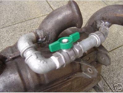
Getting closer. Testing the valves to make sure the vacuum lines and control module are working. That is some serious vacuum in those tubes. The springs on the valve are not easy to manually push open. This is with no mufflers, straight out the cats.
Getting closer. Testing the valves to make sure the vacuum lines and control module are working. This is with no mufflers, straight out the cats.
That is a fun and exciting to see it working! You can see the light at the end of the tunnel!
I recommend getting some small heat shield socks to wrap around vacuum tube on final install with mufflers (I used spark plug boots/socks). Also some protection on sharp heat shield edges where vacuum tube runs through to prevent tube getting severed over time from vibrations.
Excited for ya. keep those videos coming
Will do and thanks to you for all your help with this project.
Will do and thanks to you for all your help with this project.
Anytime!!
So where did you tap in to the engines vacuum line? Also share how you installed controller box and got power!! I should have taken pics, but I zip tied controller remote box to side of air box or some of the larger cables that run along the right side engine wall. Also mounted the actuator on the small bolt that is next to the steering fluid reservoir. same location they mount oem pse actuator.
So where did you tap in to the engines vacuum line? Also share how you installed controller box and got power!! I should have taken pics, but I zip tied controller remote box to side of air box or some of the larger cables that run along the right side engine wall. Also mounted the actuator on the small bolt that is next to the steering fluid reservoir. same location they mount oem pse actuator.
There is a plug on the left side of the transmission with a little rubber cap on it that I used for the vacuum source. To access it you have to remove the underbody tray that covers the middle of the car. Then the line needs to be run across the subframe and up into the engine bay on the right side.
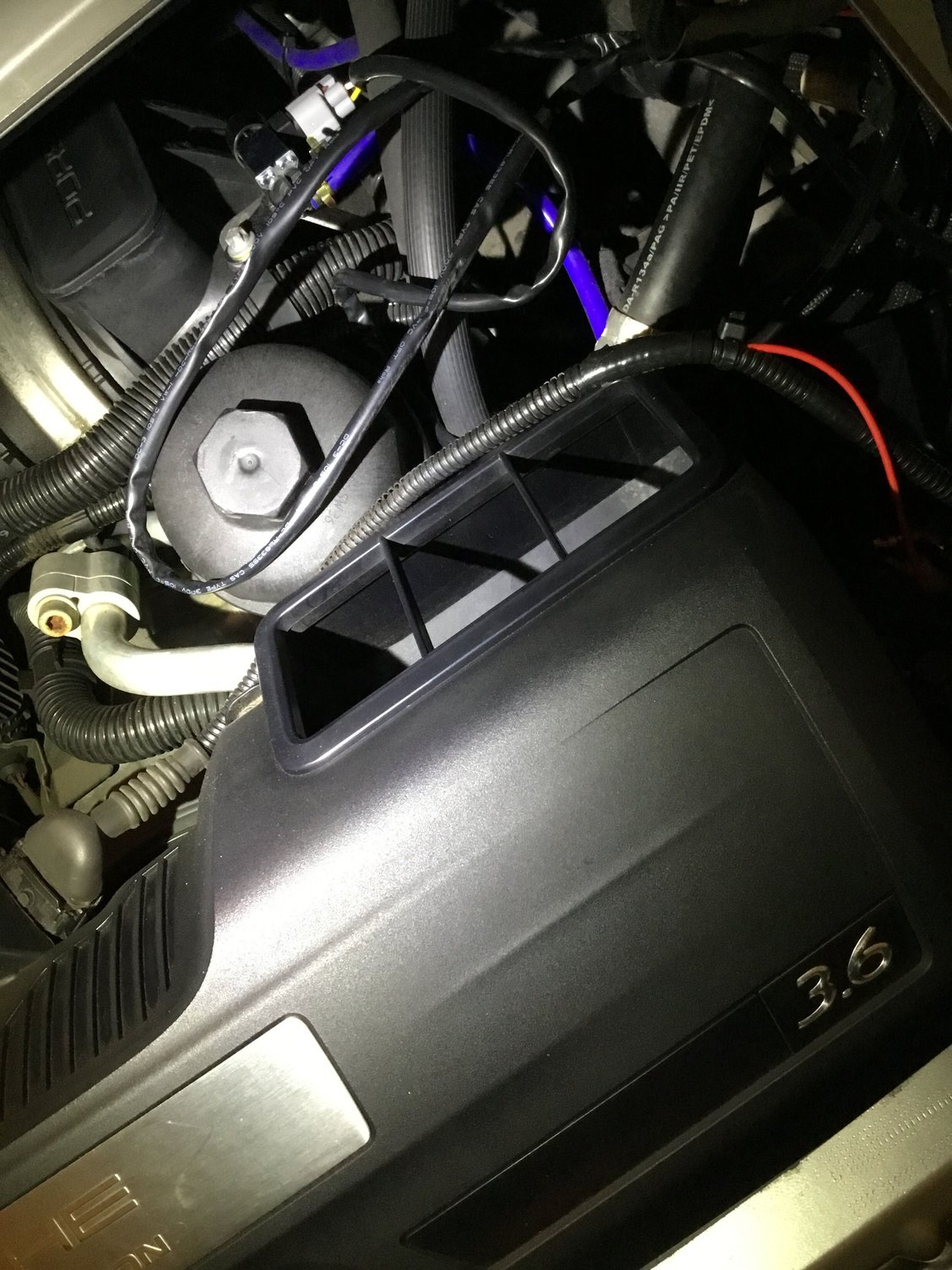
My 12v source came from the red wire that is inside the wire loom that attaches to the plug that goes into the airbox.This is a switched 12 volts meaning it is only hot while the car is running or at least the key is in the ON position. I carefully exposed about 1cm of it with a razor blade then soldered the red wire from the controller to it, wrapped it in heat sink tubing, and then taped the whole thing secure. I used one of the engine mount bolts for a ground. You can see the red wire coming out of the loom here and also the grey and black actuator in the background with white and yellow wires coming out of it. There are still miscellaneous wires running around from the control box in this photo but I will tidy those up after the mufflers are mounted.
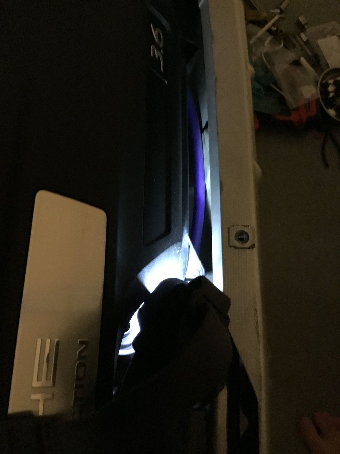
Since I don�t have the mufflers with valves welded in yet I haven�t permanently mounted the control box or the vacuum lines running to the mufflers. I want to get them back and bolted to the car before I permanently mount everything in the engine bay. I did run the vacuum line to the left side muffler behind the deck lid locking mechanism instead of between it and the airbox. I like how it is invisible now unless you really lean in to look for it. There is a little channel inside the rear body you can run it through.
There is a plug on the left side of the transmission with a little rubber cap on it that I used for the vacuum source. To access it you have to remove the underbody tray that covers the middle of the car. Then the line needs to be run across the subframe and up into the engine bay on the right side.
My 12v source came from the red wire that is inside the wire loom that attaches to the plug that goes into the airbox.This is a switched 12 volts meaning it is only hot while the car is running or at least the key is in the ON position. I carefully exposed about 1cm of it with a razor blade then soldered the red wire from the controller to it, wrapped it in heat sink tubing, and then taped the whole thing secure. I used one of the engine mount bolts for a ground. You can see the red wire coming out of the loom here and also the grey and black actuator in the background with white and yellow wires coming out of it. There are still miscellaneous wires running around from the control box in this photo but I will tidy those up after the mufflers are mounted.
Since I don�t have the mufflers with valves welded in yet I haven�t permanently mounted the control box or the vacuum lines running to the mufflers. I want to get them back and bolted to the car before I permanently mount everything in the engine bay. I did run the vacuum line to the left side muffler behind the deck lid locking mechanism instead of between it and the airbox. I like how it is invisible now unless you really lean in to look for it. There is a little channel inside the rear body you can run it through.
very nice! That's more or less how I ran my vacuum lines and power source as well, except I didn't tap in to the transmission vacuum starting point. Glad it all worked out when you tested it !
@qikqbn confirmation that the check valve is oriented correctly...valves stay open when car shuts off. I then hit the OFF button and they closed.
Awesome, thanks for the video Chris! I like geeking out over this stuff because it works as I suspected and now you know that those cold morning starts are gonna sound great! The remote actuator unit also remembers it's last setting so the green "on" light will remain in the on position when you start the car up again as well. I hope you are feeling more at ease about the whole process and being able to see and confirm how everything will work. Looking forward to hearing it when it's all done... although it won't sound as loud as your "current" straight pipe setup Thanks for sharing your journey and progress!


 09-27-2019, 12:12 PM


 Anytime!!


 Thanks for sharing your journey and progress!