When you click on links to various merchants on this site and make a purchase, this can result in this site earning a commission. Affiliate programs and affiliations include, but are not limited to, the eBay Partner Network.
DIY - Wiring High Beams and Indicators to Aftermarket Steering Wheel Buttons
I recently installed a 997 cup car wheel on my 997.2 GTS and also wanted to wire buttons for the horn, high beams and indicators directly to buttons on the wheel. The disassembly, calculations, testing and wire diagram took me about 8 hours total. I did about 6 of them for you here. All you need to do is some disassembly and soldering if you want to replicate this. I would estimate that it would take 3-4 hours to do this if this is your first time removing or disassembling these components. I could probably do this in under 2 hours having now done it already.
Note this is for documentary purposes only and you attempt any of this on your own at your own risk.
Tools:
Needle nose pliers
T8 and t10 torx
1/4 inch flat blade long screwdriver
soldering equipment
2x 1500 ohm 1/2 watt 1% resistors
2x 680 ohm 1/2 watt 1% resistors
wire,
.11 in female tab connectors
3x momentary switch SPST
heat shrink
patience
good music
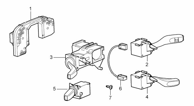
In order to do this, you will need to disassemble (gasp!) your steering wheel module cluster which includes five separate modules:
1) Control module
2) Wipers
3) Indicators and high beams
4) Cruise control
5) OBC
These modules fit together Voltron/Power Rangers style into a mega cluster with the latter four modules connecting to the control module.
Here is what they look like corresponding to my numbering above:
We will be dissecting #3 today.
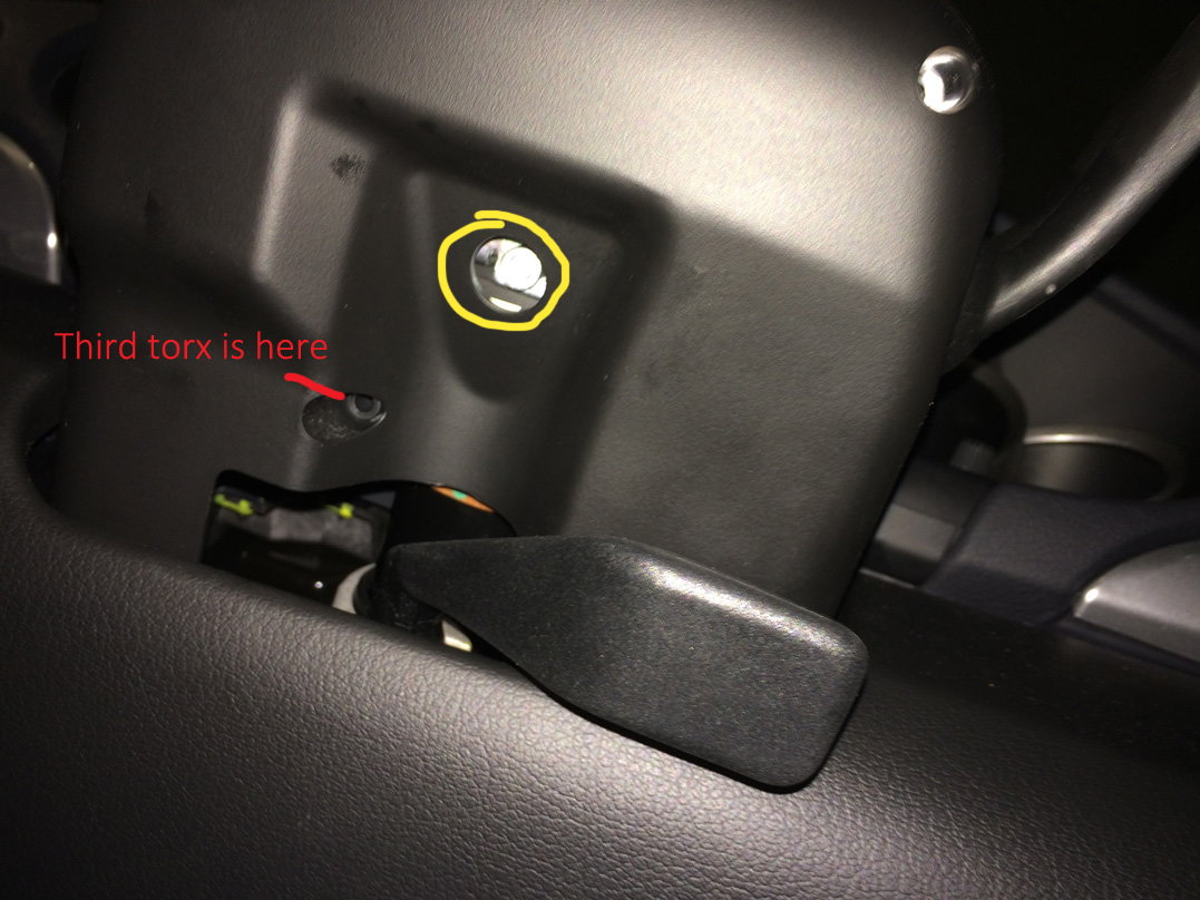
Firstly, you'll need to remove your steering wheel, upper and lower steering wheel switch housing, and clockspring.
You can do all of that first by following instructions in this thread: https://rennlist.com/forums/997-gt2-...ing-wheel.html
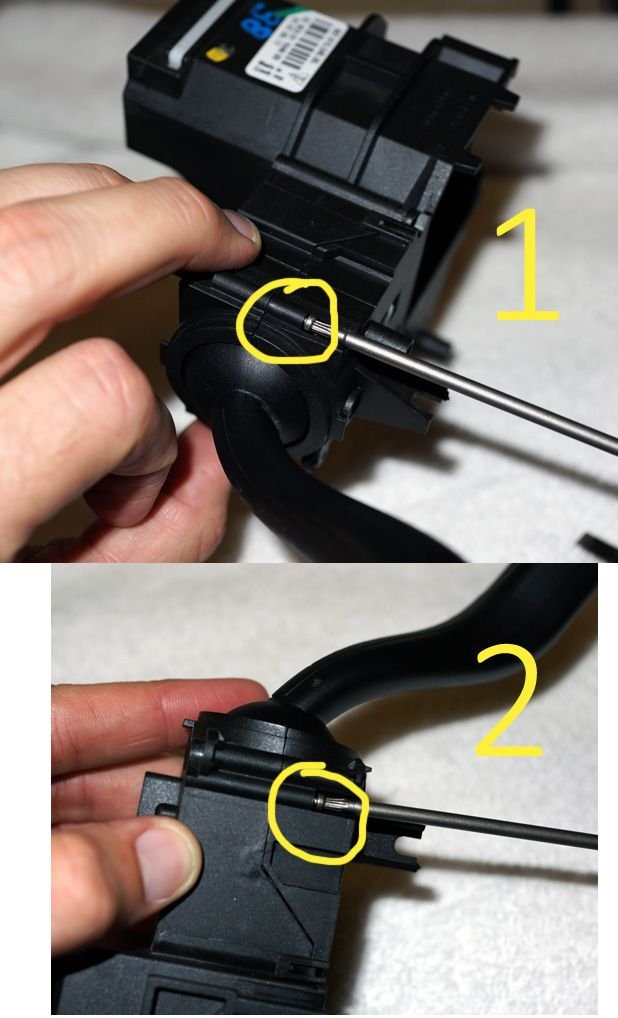
HOWEVER, that article states there are only two torx screws that need to be taken out to remove the lower switch cover but in fact there are THREE torx screws that need removing. The third is on the underside of the switch cover on the fore, center section of the cover. Here it is (while you're in there, also remove that larger torx screw (circled in yellow) that holds the ground plate to the steering wheel control module:
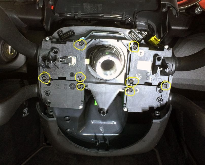
Okay, now you're into the thick of it.
Start undoing torx screws with a T8 bit. Undo all eight screws circled in yellow. They are all black and about 2 inches long.
One you have that completed, you can easily remove the lower two modules and set them aside. There is a cable connecting to the cruise control module (lower right module) that you can remove. Do the same with the wiper and set those aside.
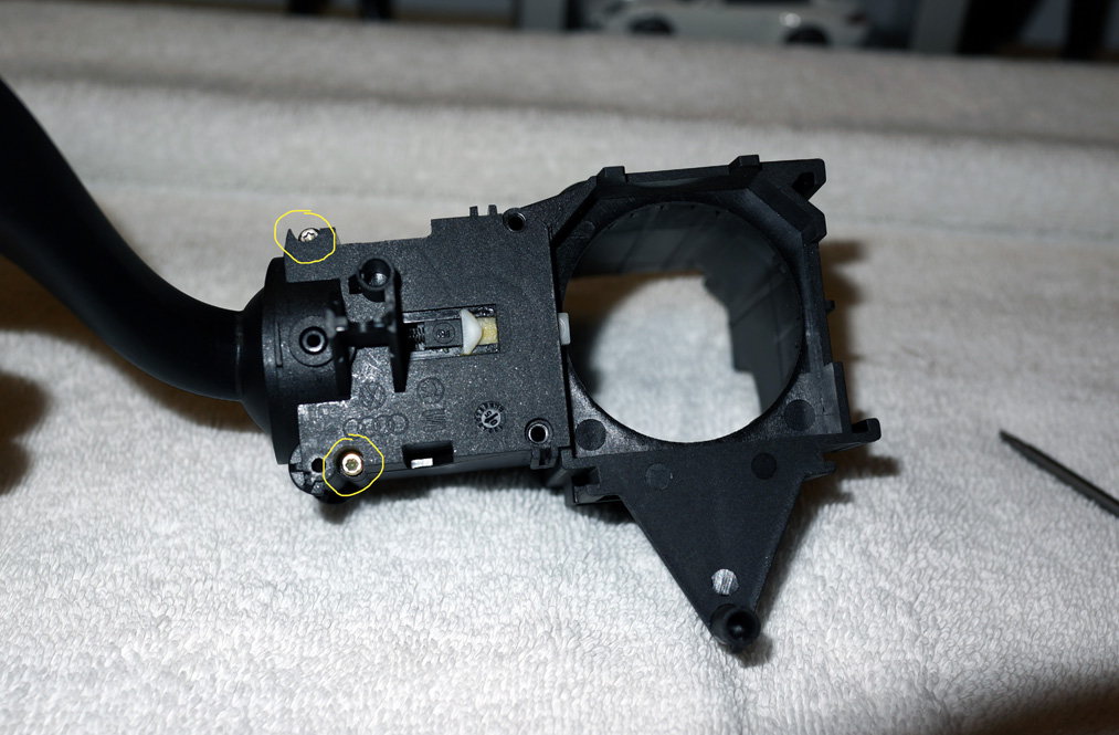
Now you can remove the indicator and high beam switch carefully from the steering wheel control module.
Luckily for all of us I bought a stand alone used unit on ebay to dissect in case I broke anything on it (I didn't thankfully).
Here is what that unit looks like by itself
Now remove the two torx screws (t8) circled in yellow.
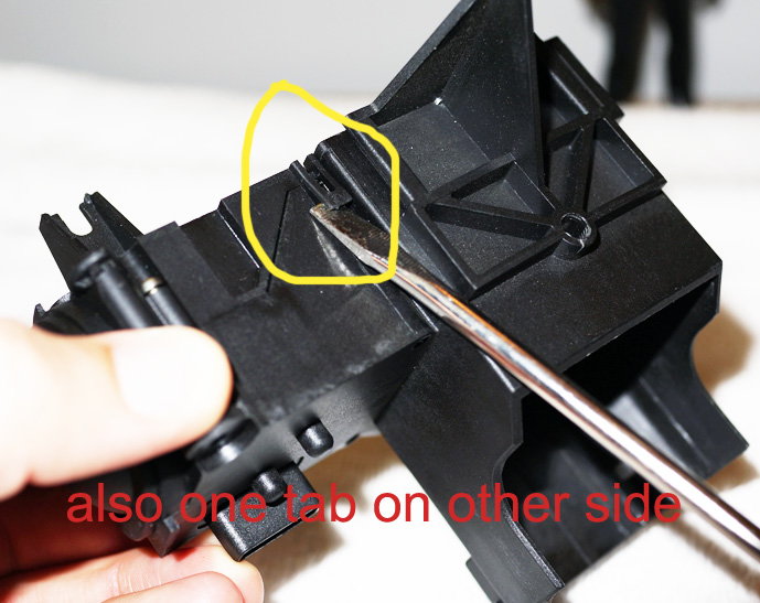
Next CAREFULLY pry the two tabs on either side of the housing
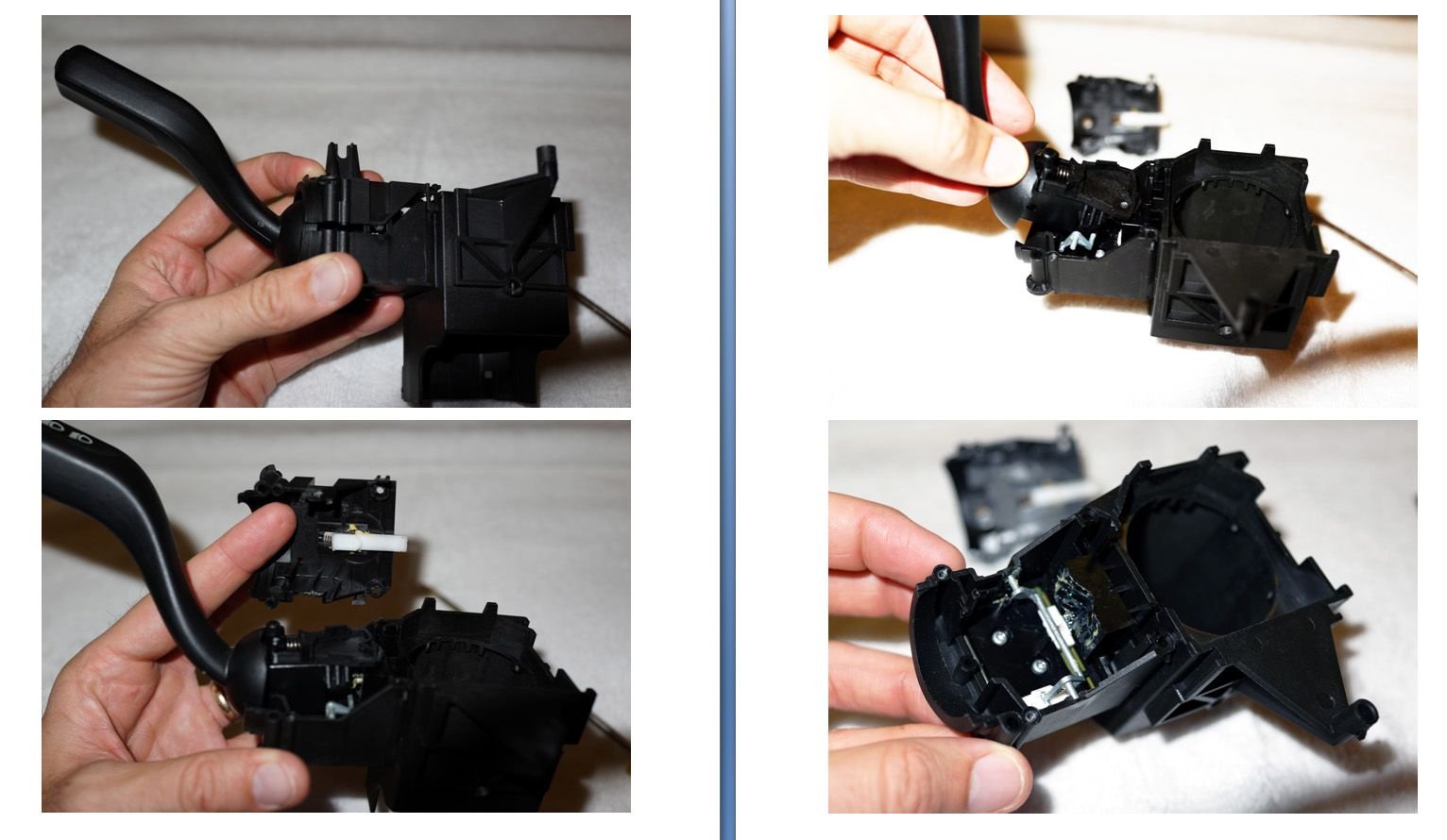
IMPORTANT: THIS COVER IS SPRING LOADED AND WILL POP OFF SENDING INTERNAL PARTS EVERY WHICH WAY IF YOU DO NOT HOLD IT DOWN WITH YOUR THUMB OR FINGER AND SLOWLY SEPARATE IT. Ask me how I know this.
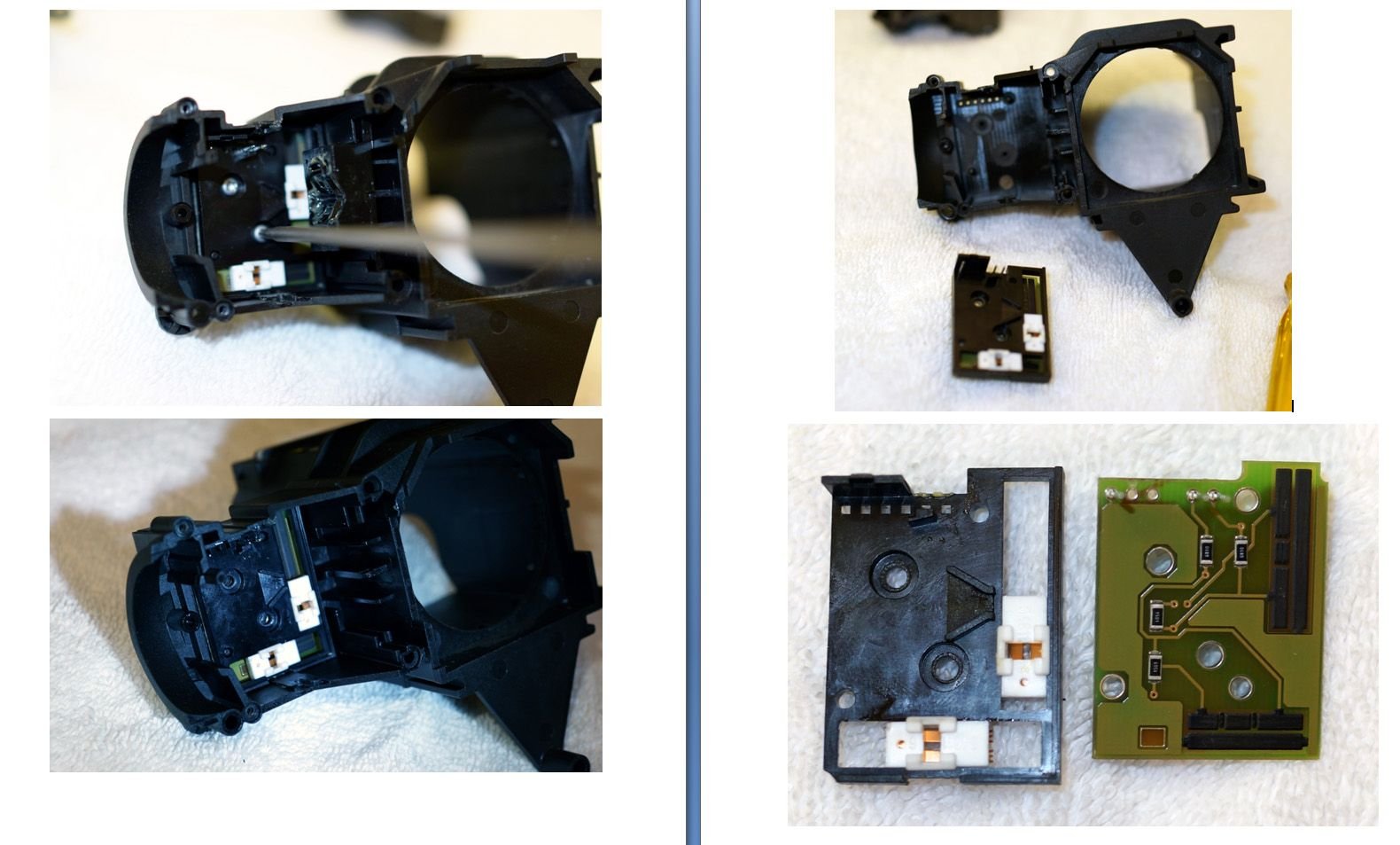
Now you will have exposed the innards:
All of these parts are free floating and can easily be removed with you fingers and set aside.
The parts are the control arm stalk, the metal rod fulcrum and the black plastic backplate (all the white grease on it).
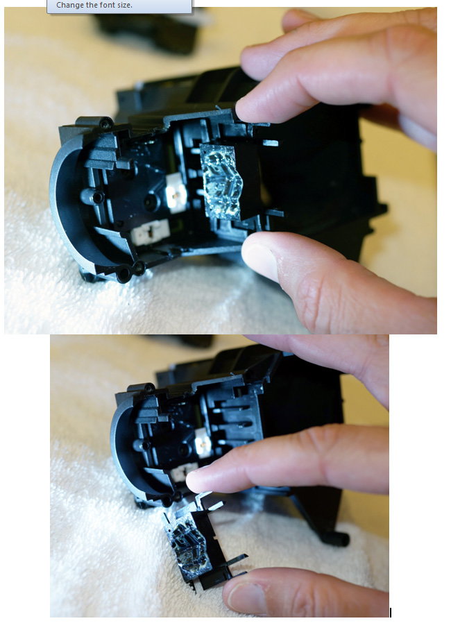
Now remove the two t8 torx screws in the housing to reveal a sled/slide connector and a circuit board:
here is where it gets interesting.
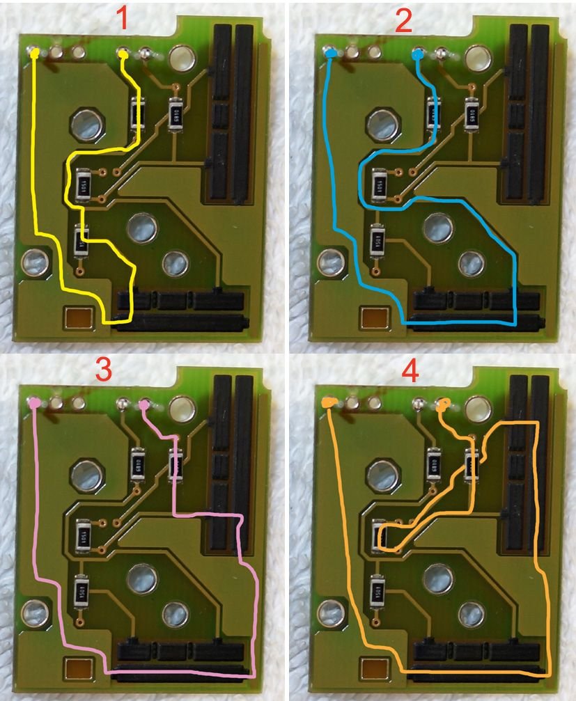
There are four paths that flow to two leads. Two paths to each lead. A copper 'U' shaped rake on those white sleds connects the paths.
The right sled is moved by pushing the indicator up or down and the bottom sled by moving the high beam fore or aft.
The leads connect to the steering wheel control module and the module translates a signal from this board into inputs based on the total Ohms as calculated by the summation of resistors in series for each respective circuit:
1) Flash High Beam - 2180 Ohms
2) High Beam ON - 680 Ohm
3) Indicate Right - 680 Ohm
4) Indicate Left - 2180 Ohm
Here are the paths corresponding to the numbers above knowing that the current will follow the path of least resistance:
Okay.
So if you're still with me you'll see that this is pretty easy to wire up.
Firstly, we can get rid of #2 High Beam On. We wont use that circuit. We will only use Flash High Beam for the button on the steering wheel.
(Some people asked me why I think there are two signals for essentially the same thing, high beams. It's because you can flash your high beams even if your driving light dial is switched 'off', 'home' or 'parking lights'. HOWEVER, you cannot turn your high beams to the ON position unless your driving lights are ALSO turned ON. The steering wheel control module sends these two separate inputs (high beam flash or high beam ON) to the CAN which then judges whether to let your high beams on based on your driving light dial position)
So in order to externally wire this circuit we need to connect a 1500 ohm and a 680 ohm in series on a jumper wire that connects to the peg on this board and the switch. Then we connect the other end of the switch to the ground and we are golden. We do a similar process with the Left and Right indicators.
I had an engineering friend help me with the resistors in circuit vs parallel math for the indicators only and this is what we calculated:
We were at first worried about what would happen if I switch ON BOTH Left AND Right indicators. Wired this way, even if both are pressed at the same time, the module will only read a 680 ohm signal and only indicate 'right'.
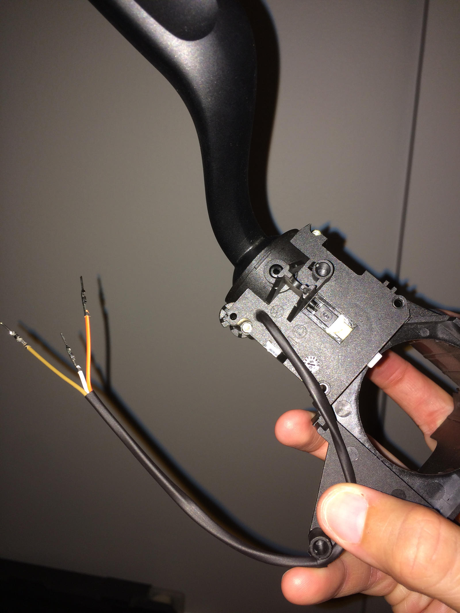
For whatever thankful reason the manufacturer put pegs on the INNER side of this board. We can still plug it into the control module using the outer pegs so it can function just as normal while ALSO having the option to attach additional wires that extend from these inner leads that go to the steering wheel buttons:
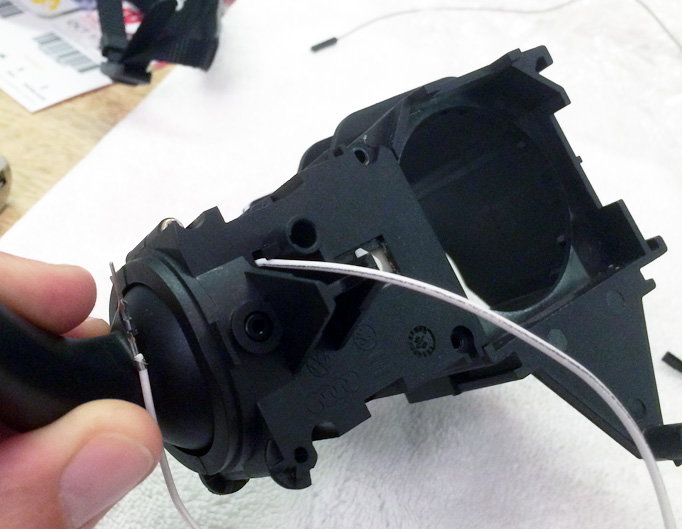
The manufacturer was also kind enough to have a predrilled hole on the top portion of the indicator module housing that allows the wires connected to these pegs to exit. How very nice of them.
So I will route these wires to the back of the lower switch cover, connect them to a curly wire, run that to the steering wheel and wire in a few resistors.
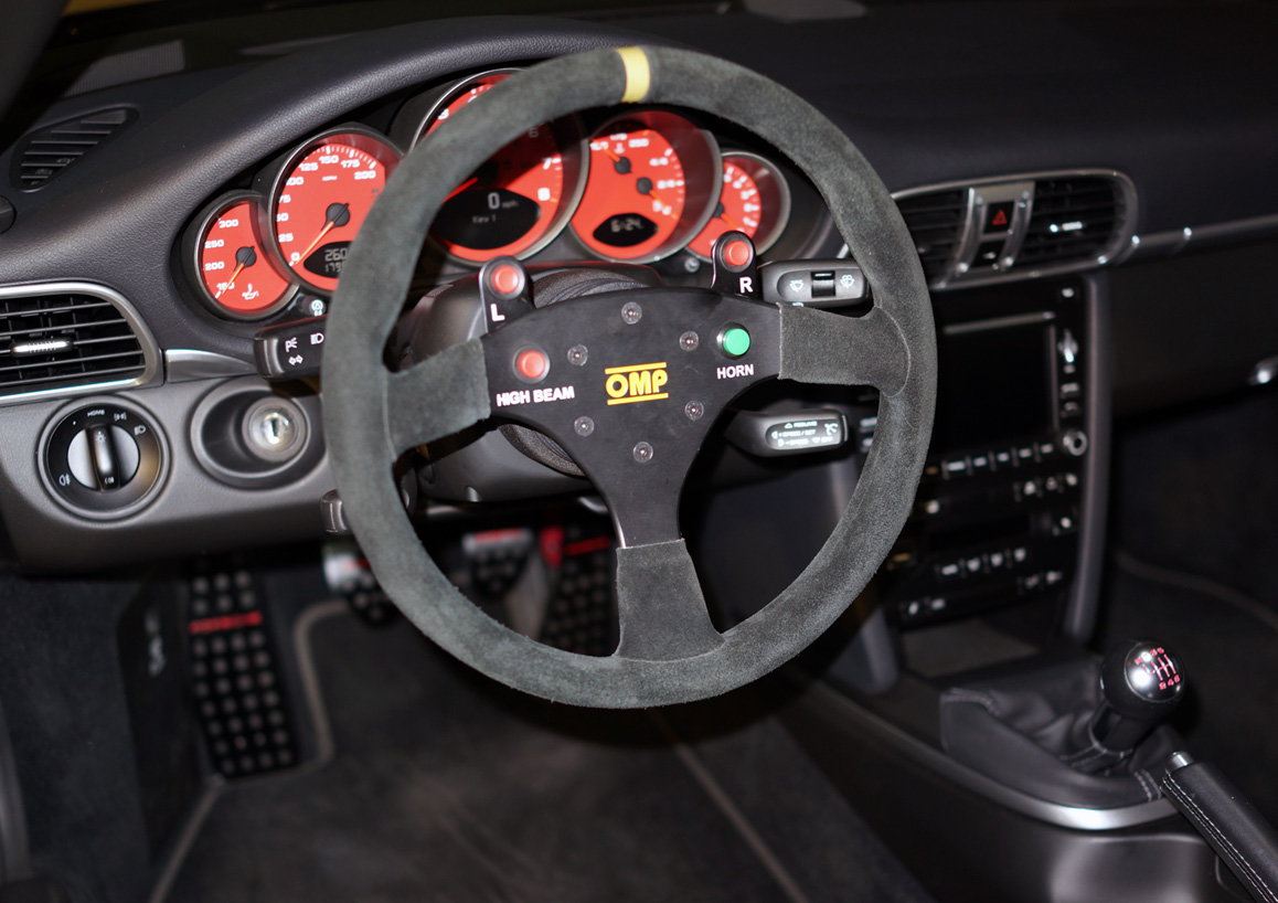
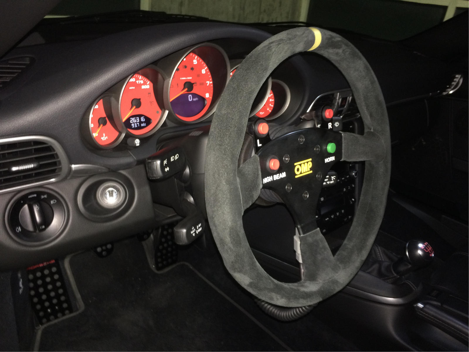
They will connect to this wheel:
Stay tuned over the next few weeks as I do some soldering and show this finished product. I'll update progress in this thread.
oh man, you have answered my call for help! lol. I am bookmarking this, should definitely be added to stickys. Please keep us updated! I want to note my brain almost just exploded I will need to try and read this again when I am rested. LOL
oh man, you have answered my call for help! lol. I am bookmarking this, should definitely be added to stickys. Please keep us updated! I want to note my brain almost just exploded I will need to try and read this again when I am rested. LOL
I think I remember you saying you need the horn wired right? That is MUCH simpler.
Simply wire one lead from PEG 1 and another lead from PEG 2 on the springclock connector to either of the pegs on any of your buttons and the horn will work just fine. Mine does.
Thanks for the great write-up and pics...and even some back-of-the-envelope calculations. Curious - what are the buttons labeled "L" and "R" - labeling seems redundant?
Thanks for the great write-up and pics...and even some back-of-the-envelope calculations. Curious - what are the buttons labeled "L" and "R" - labeling seems redundant?
Maybe I'm misunderstanding you but button 'L' is 'indicator left' and button 'R' is 'indicator right'. I wanted these buttons on the wheel because it was awkward reaching for the indicator stalk after installing the OMP wheel and spacer. The reason I went with an aftermarket wheel was to bring the wheel closer to me and free up some knee space since I'm so tall. So this project was built out of necessity.
Hope that answers your question.
Edit: My reason for labeling them was for consistency, for anyone else who may drive the car (which is never admittedly), and because I think it looks cool... in that order.
DIY - Wiring High Beams and Indicators to Aftermarket Steering Wheel Buttons
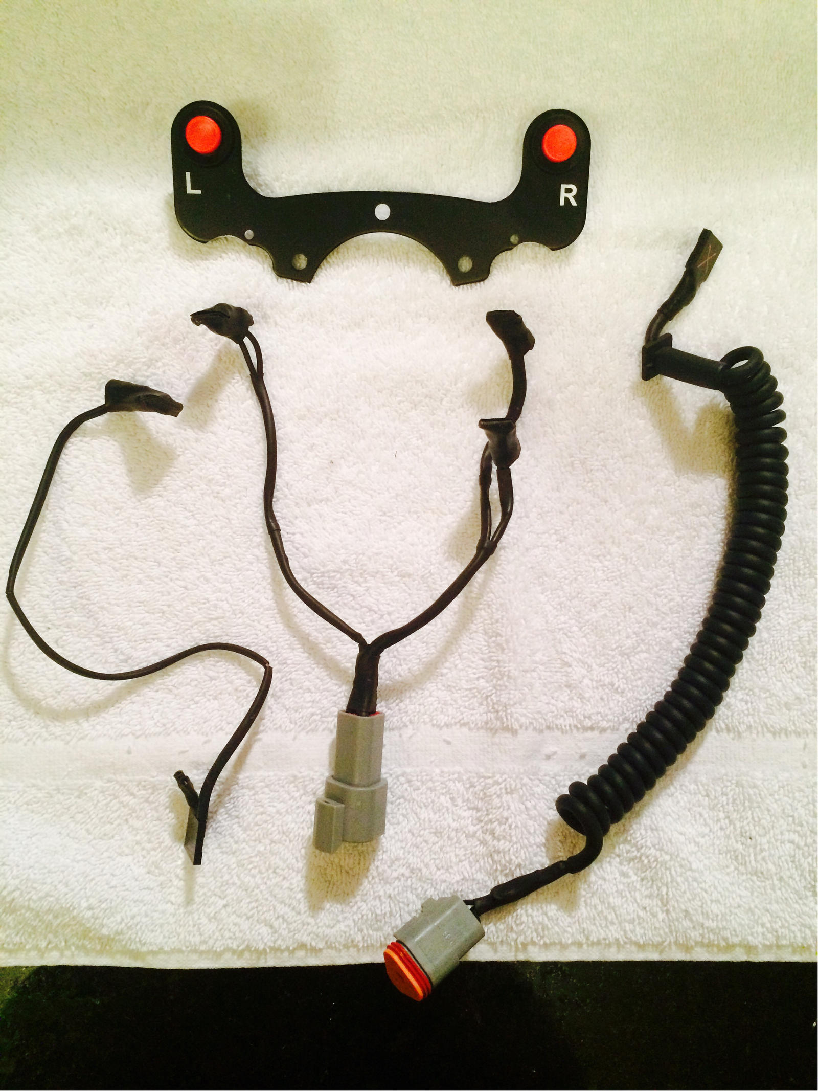
Finished the project last night. I fabricated a curly cord harness and a wiring harness for the wheel. A hub spacer is en route and will be installed this weekend.
Here are what the harnesses look like after heat shrinking everything and adding in a 1500ohm resistor to the LEFT indicator leads. I reapplied the shrink on the horn and airbag leads to close the gaps in the shrink you see here.
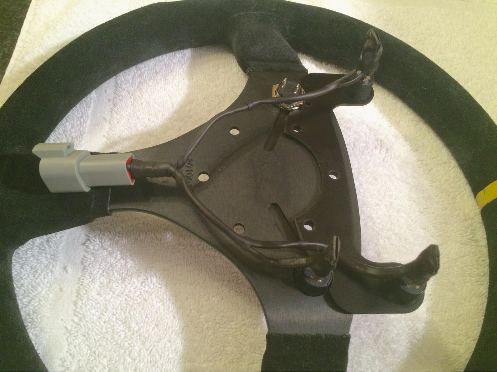
Here is the steering wheel harness mounted. Apologies for the poor lighting. It was 2am.
Here is the finished indicator wiring. I later added a clip connector that clips into the square connector (red X on it) on the other end of the curly cord.
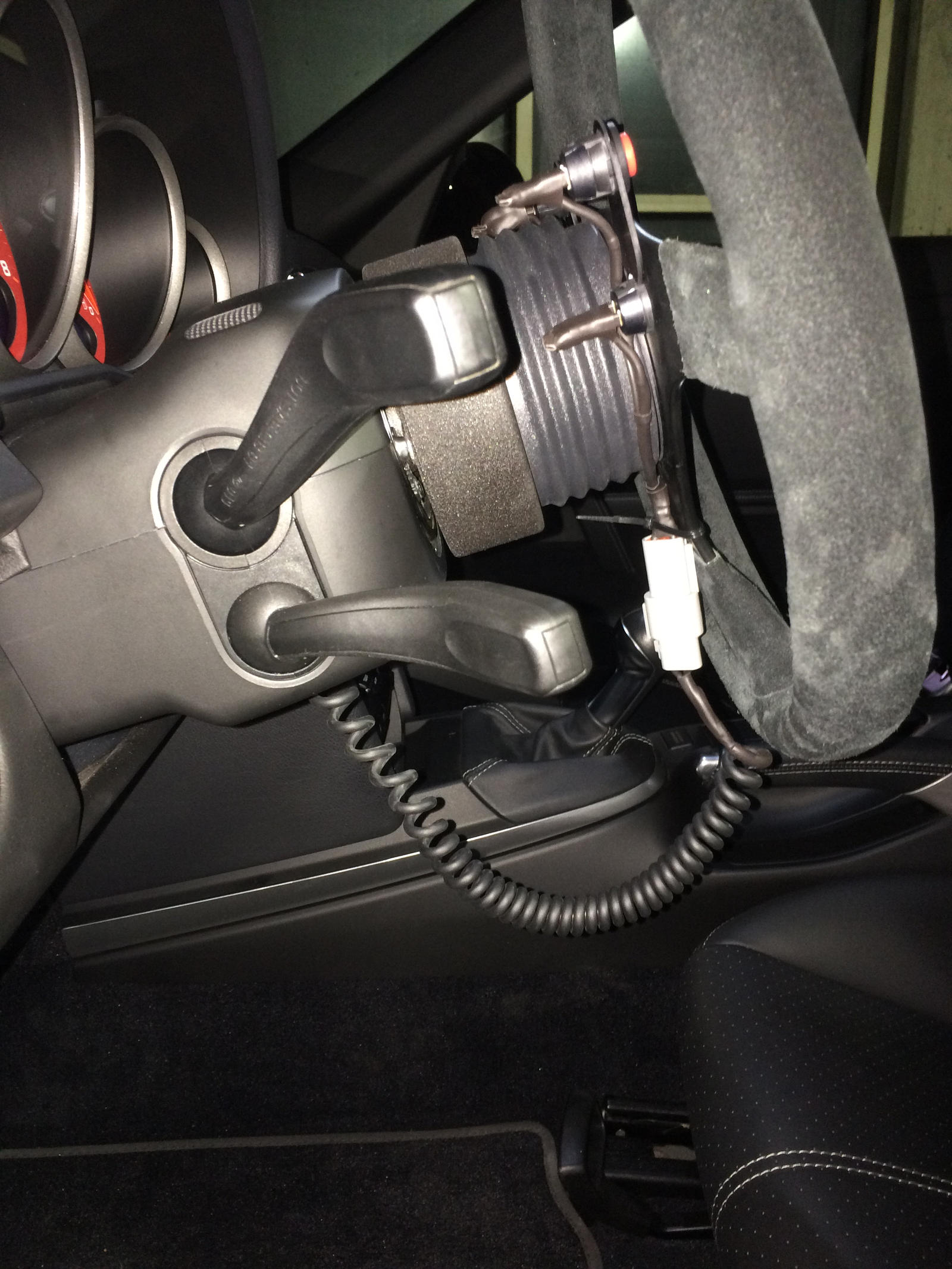
The hole underneath the steering column in the center of the lower cover fits the curly cord plug perfectly.
After the spacer is added the steering wheel harness will be zip tied to the spacer instead of the lower third spoke on the wheel for less curly cord slack.


 09-16-2015, 03:40 AM