When you click on links to various merchants on this site and make a purchase, this can result in this site earning a commission. Affiliate programs and affiliations include, but are not limited to, the eBay Partner Network.
I have a 2006 Carrera 4 wiring book (pdf). What section are you referring to?
For the control unit for the airbags, I think it denotes jacketed and or shielded cable, so that the + and - signals are isolated from the others electrically and from chafing and or shorting to ground.
O2 sensors signal output +/- voltage (not the heaters) connected to the DME also with this symbol shown. The O2 sensor is actually a thermistor (resistance highly dependent on temperature of the device). The DME sends out a constant current to the O2 thermistor, and the amount of voltage the DME needs to develop for each sensor to achieve the current target value is a function of the temperature of the sensor. The DME measures that voltage directly within itself and determines whether it's in range or not, and if not, changes the mixture (air/fuel) to move the sensor hotter or cooler (lean/rich).
Tried it and the best I got was a runic symbol lol.
On that chassis try sheet 12 for the PSM, its in there multiple times.
I know the CAN protocol for these cars is ISO9141-2 which I believe uses shielded cable but not sure if that is what's indicated.
The PASM module also works on current to control the position of the damper adjustment spool. I was reading a thread on the 996 board where someone was going to monitor the signals to each shock depending on the PASM level selected, and found some spec about how many milliamps was required to put the damper in a particular mode of stiffness. No current meant totally retracted spool valve, then additional current moved the spring loaded spool valve against the spring force (coil of wire-solenoid action).
In some cases (like your drawing), TP (twisted pair) is specified without the special symbol but every time the symbol is indicated, TP is noted.
Thanks! So my second guess was correct. Glad I feel validated lol
Originally Posted by Ericson38
The PASM module also works on current to control the position of the damper adjustment spool. I was reading a thread on the 996 board where someone was going to monitor the signals to each shock depending on the PASM level selected, and found some spec about how many milliamps was required to put the damper in a particular mode of stiffness. No current meant totally retracted spool valve, then additional current moved the spring loaded spool valve against the spring force (coil of wire-solenoid action).
I am actually not working on the PASM as it was just used for reference. I am working on a 997 turbo rwd conversion module as only one company makes one. I am using the diagrams to emulate the front diff actuator signal to the PSM ecu in order to fool it into not sensing a discrepancy in the circuit. I purchased "that" companies' module but it costs way too much for what is probably a box with some minor circuitry and some resistors in it. I was hoping to verify my findings and possibly offer something down the line at a much better price factor. There are two connectors, the temp sensor and actuator signal over canbus. The temp signal is cake to emulate, but the can signal is a bit more work. I have all the equipment to test this but unfortunately this stupid symbol was throwing me off.
Originally Posted by yelcab
TPx, TPy, TPz,
Twisted Pairs.
Thank you as well, I have all my diagrams on my laptop and its a pain to use them sometimes due to the fact that all the pages are cut into pieces to fit on the screen so its a game of cat and mouse.
I should stick to boeing diagrams.
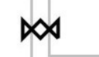
I was wrong... Twisted pair. (The symbol is not connected to ground)
It's alright, I consider twisting to be a form of "shielding" considering both are used to reduce electromagnetic interference.
Both answers solve to assist my purpose of emulating the signal I have.
Funny, looking at the symbol now, it looks like a twisting motion, seems obvious all of a sudden.
A twisted pair keeps the impedance between two wires consistent. Think of how stereo headsets would sound if you could move the wires in the cable further apart.
A twisted pair keeps the impedance between two wires consistent. Think of how stereo headsets would sound if you could move the wires in the cable further apart.
Ironically I use twisted leads and concentric for any of the harnesses I make but trust me I forget stuff sometimes and end up looking at something for an hour until it finally hits me.
I am on autopilot mentally most of these days

 04-09-2024, 11:53 PM