When you click on links to various merchants on this site and make a purchase, this can result in this site earning a commission. Affiliate programs and affiliations include, but are not limited to, the eBay Partner Network.
It's been a long time since the last update, so here it is for those who might be interested.
It's been a surprise to me how much work is required to get something like this off the ground. PV997 took a promotion at work, which also required a promotion in work hours, and as motivated as he is to keep things moving, he was unable to devote much time to the project. He is still involved, but has decided to take a back seat because of other commitments. For this reason I've been handed the reins to take it forward.
So for the last month or so I've been fully immersed. I'm fortunate enough to be retired, and as someone who loves a good project, it has pretty much taken over most of my waken hours.
So here's where we are at.
All of the individual components that will go into the sensor have been acquired. It's surprising how much time has been taken to find for example a simple wiring exit grommet that will stand up to the environment. But enough said I've got everything I need in my possession except for the CNC'd aluminium housings, which were ordered yesterday. I'm expecting them to arrive in a few weeks. I've ordered 20 housings to finish the final testing and then test the waters of people actually wanting to pay for them.
Whilst our intention was to put all the info out there so people could make their own, to be frank the level of knowledge I've needed to acquire so a sensor can be made so it will work correctly, and it's of high quality and will stand the test of time is substantial. Not to mention that you would need a bench transmission that's pulled apart so you can tune it correctly. I didn't really know what we were getting into when we started. It has been a bit of a rabbit hole.
So my personal plan at this stage is to make sensors and sell them. The price? I'm thinking around the US$500 mark at this stage, which will cover the sensor production cost and a little extra to motivate me to make them, and also to justify to my darling wife the time and cash that has been spent on this 'hobby' that seems to have taken over much of my life.
Initially I'm expecting to have Cayman/Boxster sensors available in a few months once the final testing has been completed, and 911 sensors afterwards as these will be sent to @stjoh in the US for testing and tuning on his bench 911 transmission.
I'll post updates as these come.
There has also been significant progress with the speed sensor. In the last month I've spent a lot of time on this, and identified the electronics required and done a load of testing to confirm functionality. In fact it's far more capable than the OEM sensor. There has been a lot of improvement in this field of electronics since the OEM sensor was created nearly 20 years ago. Initial plastic housings/circuit boards etc ordered and full in car testing will happen once I get all the parts. Final sensor will be in an aluminium housing.
The price? Probably about the same as the distance sensor or maybe a little less. Even though the sensor is smaller, the cost of a housing is about the same due to it being quite a detailed part, and the electrics are significantly more expensive. There was the option to skimp and choose a sensor setup that was similar in performance to the OEM sensor, but I'd prefer to take advantage of the best that's available.
Image below of the housing CAD drawing.
Last edited by jjrichar; Jun 28, 2024 at 04:25 AM.
This thread is pretty incredible. It encapsulates everything that's great about Rennlist. People are taking on challenges with our cars in a thoughtful, data-based manner, with feedback from other smart members along the way. Thanks to everyone who's contributed along the way. I hope this sensor gets out to the public soon. Unfortunately, it won't be soon enough for me since I want to get my 987.2 Cayman back on the track this summer. So a couple of questions for the braintrust:
1) Does anyone see any meaningful differences in the sensors third-party manufacturers offer? Some require less soldering by the technician (fewer points of future failure), which seems like a positive. It sounds like the OP identified some differences in the sensors, the circuit, and the calibration approaches. Is there anything to be aware of before purchasing? Feel free to PM me if you don't feel comfortable sharing your opinion publicly.
2) There was quite a bit of useful conversation about the calibration approach and potential pitfalls. Any thoughts on the best approach? The point about battery disconnection is subtle and I haven't seen others mention it.
I thought I'd use your questions to talk about some of the differences between the different options that are available, as there are a lot of differences. I must point out that I've not had either a T design or XemodeX sensor in my hands to test, and what I'm going to put below is simply what we think is going on in each based on open source information. It might be wrong, and I'm hoping the manufacturers of the different options will correct me if I am incorrect.
I'm going to go into a bit of technical detail below of magnetic flux patterns etc, so I hope I don't put people to sleep.
I have had a Chinese copy sensor in my hands to test over the last few weeks courtesy of a workshop in Malaysia I was helping fix a 718 PDK problem. The fella from the workshop was flying into Australia so he drove to my house and we tested sensors and talked PDK for a day. They'd replaced a failed OEM sensor with this one, and were still having problems. Without going into all the details, the response didn't resemble an OEM sensor response in any respect. Freq and PWM output were all over the place for all channels. I really couldn't work out what was going on. I think these sensors are an attempted copy of the OEM sensor. The plug wasn't OEM and the pins were narrower than OEM. The workshop solved the issue by purchasing a second hand OEM sensor on ebay that worked fine.
Both the T design, Xemodex and our sensor use programmable Hall Effect sensors, which are a modern component that are very robust and reliable. The OEM sensor uses a collection of different components that work very well as a sensor when you look at the details of its output, but are seriously prone to failure as we all know.
T design sensor
The T design sensor from what we can gather uses a center mounted Hall Effect sensor. If you look at the image below that comes from the T design website, you can see how narrow the cavity is for the circuit board and sensors. Hence our assumption that the individual sensors are centrally mounted rather than on the edge.
From out testing, using a center mounted sensor presents some difficulties and advantages. The big difficulty is how to deal with the magnet flux changes as the magnet moves with respect to the sensor.
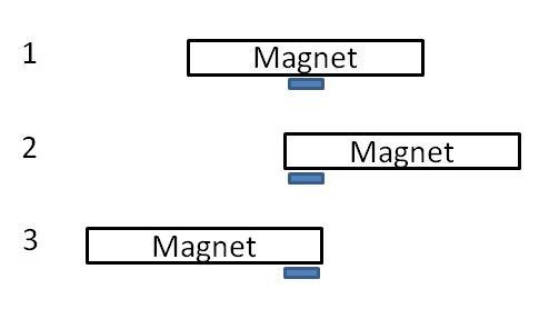
Below is an image that shows the magnetic flux change as a magnet moves over a HE sensor. You can see the center section of the plot that is linear, which is the good part of it that will result in a nice linear response that is needed. The problem is that the linear portion is only when the magnet stays over the sensor for the entire range of movement. The second image shows what this would need to look like, with the magnet being long so it stays over the sensor when it moves. Position 1 is central, with positions 2 & 3 being full deflection in either direction.
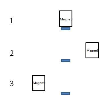
But here is the problem. The PDK magnets are a disc that are 10mm across and 6mm thick. So when the magnet moves in relation to the sensor it looks like below, where the magnet edges move well beyond the sensor as the total shift rod movement from one selection to the other is normally about 17mm, up to a maximum of 20mm, which is well beyond the 6mm thickness of the magnet.
The end result is that the flux the sensor will detect looks like this, and is well outside the linear range.
So this very non linear sensor response then needs to be changed to a very linear PWM sensor output for the TCU to use it correctly. I don't know how T design do this, as the tools within programmable HE sensors we've seen are pretty basic. There might be something completely different going on inside, but enough said that for the reasons above we decided not to go down the path of centrally mounted sensors.
Note that a critical part of sensor response is that it gives a linear PWM response as it moves from the central position to full deflection where the gear is selected. If from the calibration it's expecting an output of 8mm when a gear is selected, the sensor must give a progressive increase to this distance as the magnet moves. If there is a transmission problem, it doesn't shift correctly and the shift rod only moves 6mm rather than the 8mm expected, you need the TCU to see this and respond by not engaging the clutch and do major damage to the transmission. This is why the distance sensor exists in the first place, that being to detect accurately where the shift position is and determine if all is good prior to engaging the a clutch.
Like I said above, I've never had a T design sensor in my hands to test the response, and if they can get a linear response from a center mounted HE sensor then there is some fancy stuff going on to make this happen.
The big advantage to a center mounted sensor is that when you flip it to mount in either a Cayman/Boxster or 911, it's still located in the same position relative to the shift rod magnets.
All six wires for the T design sensor need to be soldered into the existing harness. There is limited wire for this, and the solder joints end up in a place that in my opinion is not optimal. The wire that bends into the sensor needs to be flexible to route correctly, but this is where the T design sensor solder joints will be located. Image from the T design website install instructions below.
The T design distance sensor sells I think for about US$1900. They also sell a speed sensor, I think for around the UD$1500 dollar mark, which also needs to be soldered in.
XemodeX sensor
The Xemodex sensor uses an end mounted sensor. Image below from the Xemodex website. I think this is the sensor also sold by LN Engineering. The arrow points to the channel 4 sensor. The other three channel sensors point down into the housing on the other side of the circuit board.
As you can see the sensors are mounted at the end rather than centrally. Why? Because the magnetic flux is much easier to deal with as shown in the plot below. The sensor is now always on one side of the magnet, so it will detect in the non linear region. Whilst this is a curved response, the algorithms within a programmable HE sensor are designed specifically to deal with this and provide a near linear PWM output.
You can see in the image of the Xemodex sensor above that all the sensors are mounted along one edge. In the OEM sensors, the sensors themselves aren't right in the middle. Channels 1, 2, and 4 are offset towards one edge, channel 3 towards the other. So with the XemodeX design this means that channel 3 magnet is sitting pretty much on top of the sensor when 3rd gear is selected. This can be dealt with but is not ideal.
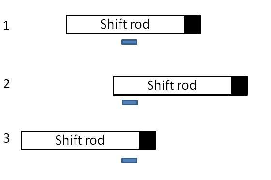
One of the biggest issues is that when you flip it over to mount in a 911. For shift rods 1 and 4, the magnet sits right at the end of the shift rod, with the shift rod made of steel. This has a massive effect on the flux detected by the sensor if the shift rod is between the magnet and sensor.
So in one orientation (Cayman/Boxster) it would look like this. No problems
But when flipped to go into the 911 it looks like this. This is going to cause major issues when attempting to achieve a good sensor response because there is a big rod of steel between the magnet and sensor.
I don't know how XemodeX deal with this issue, as we made a version just like this, found the problem and decided it wasn't the way to go.
The XemodeX sensor comes with a plug and you need to solder in the speed sensor. Not ideal but better than having to solder in the distance sensor. It retails on their website for US$2200.
JUMPS PDK distance sensor
This is the one we have designed. We've decided to name it JUMPS after the individuals who have contributed to it. No particular order of the letters. It just made a word in this order when a U was added.
J - Jjrichar
U
M - Muddtt
P - PV997
S - Stjoh
So the sensor we have designed is going to have two different versions. They both use end mounted sensors with channel 3 put on the other side to the other three. One version for the Cayman/Boxster, and the other for the 911 has the circuit board flipped over and the sensors mounted in a way that results in identical geometry of the individual sensors relative to the transmission components. I hope it's obvious from the discussion above why we have done this.
Note that what I've talked about above is just scratching the surface. There is far more complexity to it when you change how each individual sensor is mounted take into account the interference from other ferrous objects, adjacent magnet interference, magnet strength changes with temperature, etc, etc. All this combined with some fancy maths (my maths degree from 35 years ago came in very handy) and in the end you end up with a sensor that is very consistent for every channel throughout the whole range.
But the downside is that a Boxster/Cayman sensor won't work on a 911 transmission. We made this 'two version' design decision based on wanting to create a sensor that gave the most consistent response we could manage. If someone needs a distance sensor they can swap between different car types then ours won't work for them. But from my experience, if I have broken car I just want to buy a part that fixes it. I don't need it to be swapped to another car type that I don't own.
One of the things we have really worked on is making the install much easier so no soldering is required. Our sensor will have the wiring, plastic protective sheath and OEM pins installed. It's then a very simple procedure of tapping out the old pins from the plug and installing the new. I've spoken at length with workshops who replace the sensors, and one of the big ticket items to them was not having to solder in a new sensor due to the risks associated with heat cycles and oil soaked (with ferrous contamination) environment, not to mention the extra time. It's take a lot of time to source the parts but this is something we thought was worth the effort.
I'm also doing testing for the speed sensor, which I expect to have completed soon. We are also sourcing the OEM pin housing (the plug) so we will be able to offer a sensor that is a complete remove/replace item. Unfortunately getting the plugs requires a minimum buy of about AU$5000, which is a bit steep at this stage of the project. I'm hoping this full sensor pack (distance + speed sensor) including plug might be available some time next year.
You are probably aware that the reason we developed the sensor was because we thought the other options were very over-priced for what they are. The price of our sensor will be around the US$500 mark with the speed sensor being about the same when it comes along. When I can get my hands on plugs and offer the whole thing it will be about the US$1000 mark. I don't know exactly what people want at this stage, but the workshops I've spoken to have made it clear that a complete remove/replace with no soldering is by far the preferred option.
With respect to calibrations, I've not heard anything about the battery disconnect. The only advice I can offer you is to not do the 'with part replacement' routine. Only do the 'without previous part replacement' routine. The distance sensor cal part of each is the same, but the additional stuff done in the 'with part replacement' routine can easily fail and be very difficult to rectify.
Last edited by jjrichar; Jul 15, 2024 at 04:21 AM.
Thanks for the fantastic response and explanation. I, and I'm sure many others, find this useful. Maybe @Daugaard can comment on the calibration procedure, his challenges, and his resolution to the problem.
Also looking forward to proactively buying these sensors in the hopes I'll never have to use them haha.
Let me remind that both speed and distance sensors are readily available right now. Tried and tested on the roads for 5 years now and backed by lifetime warranty!
Also, sometimes it's not obvious but the biggest expense in this particular type of repair is installation. Taking PDK down, opening it correctly and calibrating after take a lot of labor, and a lot of experience. Therefore choosing the right repair shop that can do the job in one try - is incredibly important.
We work with repair shops in US and all over the world and can help you to choose one.
My first post on any of the forums as I've always had cars that didn't require in depth knowledge when it came to faults. Long story short, a few years ago I got a 981 boxter gts for a few days in exchange for a brake service on one of the customer's cars. I fell in love with the car so a few years later I made my dream come true and bought my first porsche 2019 981 cayman s. A crashed one (since i'm on a budget), it took the shop 4 months to fix it (absentee workers issue, it was an easy crash but still needed some metal/aluminum work as the rear quarter plate was quite bent).
Anyway, now 4 weeks after being roadworthy to drive and enjoying it, the P0652 error came on and the almighty “Possible R gear fault. Driving allowed'' accured. Cleared the codes, it was fine for a day and today it came back up....
I started doing a little research and found out that the speed/distance sensors are a big problem. I've found T-desing and other aftermarket deals for these parts but I'm still hoping to find better alternatives and just now found this thread and a lot of the burden has been lifted off me seeing how much enthusiasm and level of engineering @PV997 @jjrichar have done approaching this problem. Thread started in 2022 and I took 2 hours of reading to study it, and I was sure that by the endy the solution would already be given and proven. But I can see that's not the case, it just goes to show you how much effort some people will put in for others and end up giving it almost for free so that people like me and others can benefit.
I have to fix my car so I may not enjoy the fruits of this hard work @PV997, @jjrichar and @stjoh have put in, but I still want to thank you. When this project is done, I know a lot of people will be in the same situation as me and will be very grateful for the solution you will offer. I wish you good health @PV997, in the end that's what matters most.
Sorry for my bad English, I'm from Europe and it's my second language.
Nejc Grozde
I'm unable to send you a PM due to you being a new member.
Last edited by Robb M.; Aug 29, 2024 at 09:29 AM.
Reason: don't post contact info online scammers will attack you.
I have skim read this thread with interest. Way back, it was asked why the original aluminium housing couldn't be used, but I have not seen any response to this (I could have skimmed past it of course). I realise that it is probably a labour intensive messy business getting the old potting compound out, but as a DIY'er it should be possible. It makes sense to me, since this is probably the most troublesome part to source because it needs to be made in volume quantities. Would your electronics fit into the original housing?
I also noticed that it was asked why machining a housing was so expensive in low volumes, and the answer is that even with CNC machines there is a fixed machine and tool set up cost. In addition to that fixed cost is the manufacturing cost per item made up of the material cost and the time element for each fabricated part. The set up cost is apportioned equally to each part manufactured, hence the more parts, the less effect this cost has on the total cost. This is why there is an exponential type drop in price against the increase in the quantity of parts manufactured.
Amazing post. I guess you had the day off as I can't imagine putting all that together was done during a coffee break. Thanks for the time and the effort!
And I agree with you in not understanding why Porsche won't sell the sensor to out of warranty owners or to anyone else including indys as I understand it. Why not just warranty the sensor in case it fails again with no further obligation on their part? No need to warranty the whole transmission because they sell a part that's needed.
Btw....the picture above that you provided of the sensor is a picture of a $20,000 part. Doesn't look like one but I guess I don't understand modern technology. I say this since my latest out of two sensor related PDK failures came to $20,000 as full replacement was the only option. Anyone who can get a full PDK replacement for $12,000 these days is either getting a bargain worth bragging about or isn't getting the real thing.
Very interesting thread. I'm afraid I was the "victim" of this failure during Covid era, naturally just outside of my warranty period by approx 10 months. Porsche could not get my car in for 2 months because of backlog, so they recommended a highly rated local Porsche repair shop who made the diagnosis which nearly caused me to faint. All costs including installation was just over $18,000. There was none in the US, it was flown in by Porsche at no extra cost from Stuttgart as a "courtesy". The techs told me if I had done the work at the Porsche dealership it would have cost me approx 23K so I should feel better that I ended up there. Sure, I only had to sell two children so I suppose it was better
The Porsche techs told me it was a shame because the part is not made available and claimed was only worth a few dollars....and now confirmed by you! They did tell me that the new transmission would be the new version that has the "flaw" corrected.
Who really knows... but FUD was classic IBM back in the day.... early 80s for me. They had all kinds of sales approaches... one was to inform a client "no one was ever fired for buying IBM".... falls under FUD.
Peace
Bruce in Philly (now Atlanta)
Ohh my God, you made my day. I remember this phrase from my old days. I was a CIO for decades during the "golden" years of tech. Used this phrase many times when confronted with IBM competitor purchase decisions. Of course years later it eventually faded into obscurity as MS began to erode their business model. I'll never forget the time IBM sent 3 PS/2 PCs to my home for me to evaluate the wonders of the proprietary micro channel architecture and token ring!!! That was the beginning of the end for Big Blue!
Been away from Rennlist for a while and noticed this thread I started had surfaced again. Now that these sensors are out there (and working beautifully) I thought I'd comment on a few things...
First off, Porsche dealership Service Advisors are still telling people their only recourse is to replace the transmission for $20k+. If this doesn't convince you these people are dishonest and cannot be trusted then nothing will. An honest service advisor would say something like, "Porsche does not authorize PDK repair however their are alternatives available that are much lower cost. Look into it and let me know what you'd like to do". They know it, it's all over the internet. But they don't say that except in may be a few isolated cases, the standard line is still that they cannot be repaired and must be replaced. What makes anyone think these people are treating customers in good-faith on any service?
Next off, the way aftermarket sensors sprang up in response to this also had a really grubby feel. I know at least one aftermarket sensor resulted from a series of speculations among multiple commenters over in the PDK repair thread sticky. One of the commenters PM'd me with technical questions that I happily answered. He posted a picture of a prototype he had built based on the comments. Then suddenly that commenter disappeared, the photo and technical info was scrubbed from the comments, and an aftermarket sensor was announced. (Edit: clarification that the commenter deleted the info, not Rennlist.) To make matters worse, the price of that sensor was (and remains) absurdly high. To me it's clear the sensor is priced based on what a desperate owner facing a PDK replacement is willing to pay, not the fair market cost to build plus a reasonable profit. Taking advantage of desperate people may be legal but it stinks to high heaven.
And last off, a cottage industry of "PDK repair shops" has also sprung up based on all of this, and I see some really questionable practices. Some of these shops are telling people they will not replace the distance sensor without removing the PDK from the car. This can add thousands in labor to the repair cost. Many of us have shown this is completely unnecessary on both the Cayman/Boxster (where access is plentiful) but also the 911. Yesterday I helped a DIY'er pull the case off his 997.2 PDK while working in his driveway with the car on jackstands using homemade pulling tools. Even in this less than ideal working environment it went flawlessly. Now consider that shops with a lift, good tools, and trained mechanics are requiring people to pay added labor to pull the PDK. It's nonsense. There a whole video on how to pull the case in a 911 PDK here that documents every step:
Folks, the BS surrounding the "mystique" of the PDK is mountainous and everywhere. Do your own research, look into all your options, and take everything you are told by the "experts" with a grain of salt. A $6k distance sensor replacement job may seem like a bargain compared to a $20k PDK replacement. But if that $20k replacement was BS in the first place (which it is) then it's not necessarily such a good deal. There are much cheaper options for people who are savvy and willing to think for themselves.