When you click on links to various merchants on this site and make a purchase, this can result in this site earning a commission. Affiliate programs and affiliations include, but are not limited to, the eBay Partner Network.
I also love my ashtray switch. eliminates the control module cut offs for regulations abroad.
Nice and I agree it's better than the factory system in that it's on or off when you want it to be.
Originally Posted by systech
DucatiRob over the ditch and myself downunder and others have done this but using a latching relay wired to the vacuum solenoid rather than via the ECU as prescribed in the Porsche TSB so that the PSE is either ON or OFF as per the switch setting and not controlled by the ECU on a rev/speed dependent basis.
Originally Posted by systech
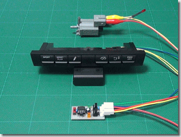
I originally bought a kit including a remote control fob from Carnewal in Belgium but then implemented a wired solution using the OEM switch panel and the latching relay
I've reinstated the missing circuit diagram in the last post.
All very doable if you're a bit handy and have a basic grasp of electronics
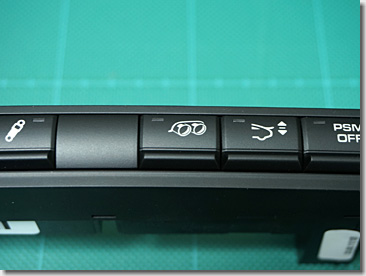
This is a great write up but unfortunately the pictures don’t appear anymore. Did you buy the dash switch console that has all 6 buttons because you have PSE, SC, SC Plus, PSE, etc or can you customize which buttons you want?
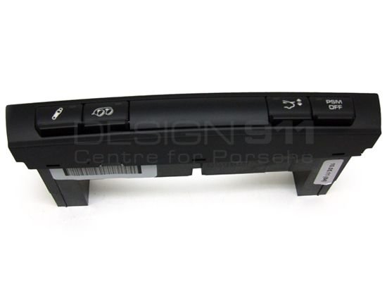
Here's a switch that only has 4 buttons, part number 99761355301A05. I'd like to find one that only has the exhaust, spoiler, and PSM buttons but I'll use this if I can't find one.
I originally bought a kit including a remote control fob from Carnewal in Belgium but then implemented a wired solution using the OEM switch panel and the latching relay
So for this latching relay we want panel mount, DPDT, and 12V? Any chance you could re-post those pictures from your original post on the 911uk forum here?
Any chance you could re-post those pictures from your original post on the 911uk forum here?
systech: Sorry the original idea and post came from DucatiRob on 911UK.com forum. The circuit diagram I posted in the last post here https://rennlist.com/how-tos/a/porsc...spoiler-384158 is the only image that I actually stored on my PC so could recover.
Nice and I agree it's better than the factory system in that it's on or off when you want it to be.
This is a great write up but unfortunately the pictures don�t appear anymore. Did you buy the dash switch console that has all 6 buttons because you have PSE, SC, SC Plus, PSE, etc or can you customize which buttons you want?
Here's a switch that only has 4 buttons, part number 99761355301A05. I'd like to find one that only has the exhaust, spoiler, and PSM buttons but I'll use this if I can't find one.
The short answer is NO. There are lots of variations of the switch panel depending on the options that you have. You will need to determine the correct panel and part number from the PET (Porsche parts catalogue) and to do this you need to know the option codes applicable (these are also listed in the PET). I bought the panel with PSE, PASM, Sports Chrono, Spoiler lift and PSM OFF but don't have the PN handy...sorry.
Now someone here got to try it and give us a good translation and feedback ;-)
Thanks I will check that out.
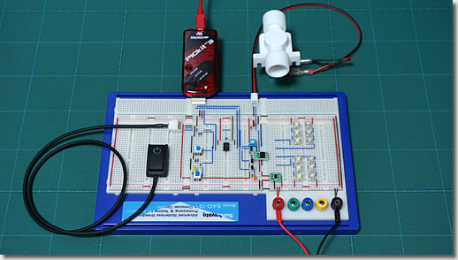
EDIT: I just read through that page and he built that control board from scratch. Doesn't seem feasbile for your average DIYer.
Originally Posted by systech
The short answer is NO. There are lots of variations of the switch panel depending on the options that you have. You will need to determine the correct panel and part number from the PET (Porsche parts catalogue) and to do this you need to know the option codes applicable (these are also listed in the PET). I bought the panel with PSE, PASM, Sports Chrono, Spoiler lift and PSM OFF but don't have the PN handy...sorry.
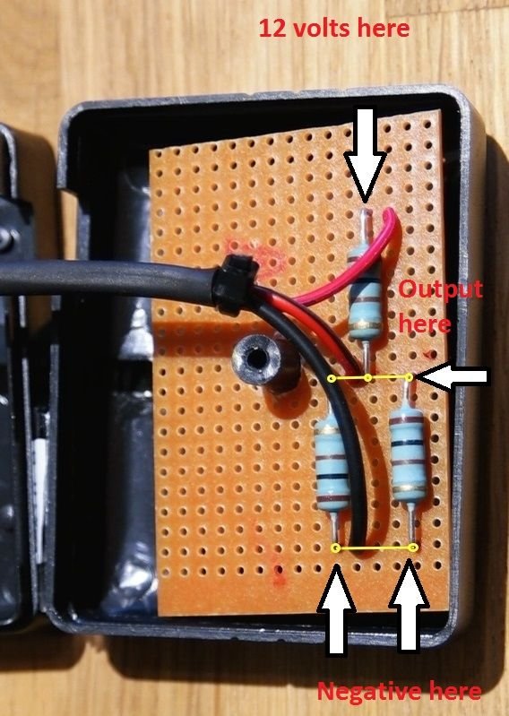
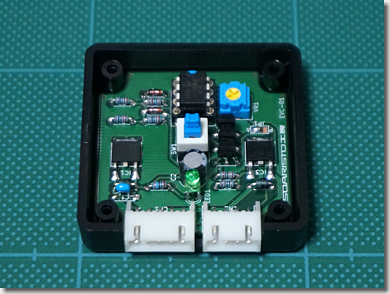
Forgive my electronics ignorance but in this photo do the yellow lines indicate that the wire and the ends of the resistors are all soldered together on the back side of the board?
In short...yes. However the voltage divider is simply used to generate a voltage of around 4 volts as required by the relay input from the 12 V input and you can do this by simply using two instead of 3 resistors where the first is around twice the value of the second. I think I used 150 ohm and 270 ohm and strapped them across the relay terminals mounted in a small plastic housing rather than using two housings as DucatiRob has done.
In short...yes. However the voltage divider is simply used to generate a voltage of around 4 volts as required by the relay input from the 12 V input and you can do this by simply using two instead of 3 resistors where the first is around twice the value of the second. I think I used 150 ohm and 270 ohm and strapped them across the relay terminals mounted in a small plastic housing rather than using two housings as DucatiRob has done.
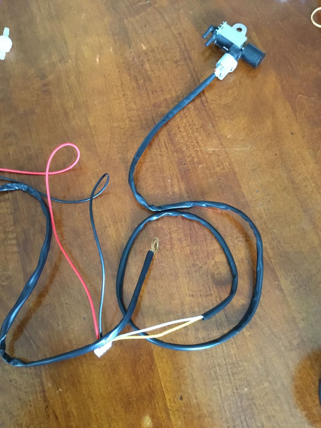
@systech did you only run one wire from the solenoid to the latching relay? I am also using a solenoid from a remote control kit but this solenoid has two wires coming out of it.
@systech did you only run one wire from the solenoid to the latching relay? I am also using a solenoid from a remote control kit but this solenoid has two wires coming out of it.
one line is for the switched relay output and the other is the ground signal. I ran two wires to the solenoid from the relay board but you could also run a wire from the solenoid to the chassis nearby for the ground signal if that is a problem.
one line is for the switched relay output and the other is the ground signal. I ran two wires to the solenoid from the relay board but you could also run a wire from the solenoid to the chassis nearby for the ground signal if that is a problem for you.

 09-12-2019, 01:27 PM