When you click on links to various merchants on this site and make a purchase, this can result in this site earning a commission. Affiliate programs and affiliations include, but are not limited to, the eBay Partner Network.
As the title says I've got a 2003 996 with 3.6L 3 chain engine that I am trying to set the timing with poor results so far. I am following a book by Wayne R. Dempsey called 101 Projects for your 911 1998-2008 996 and 997 which probably I am mistaking something somewhere along the steps as it jumps back and fourth between 5 chain and 3 chain engines which kind of makes me go nuts...
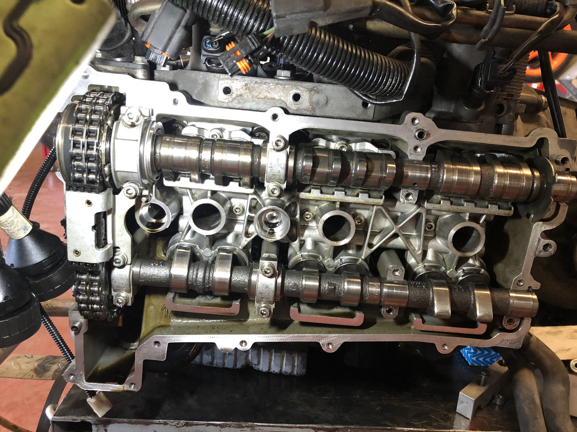
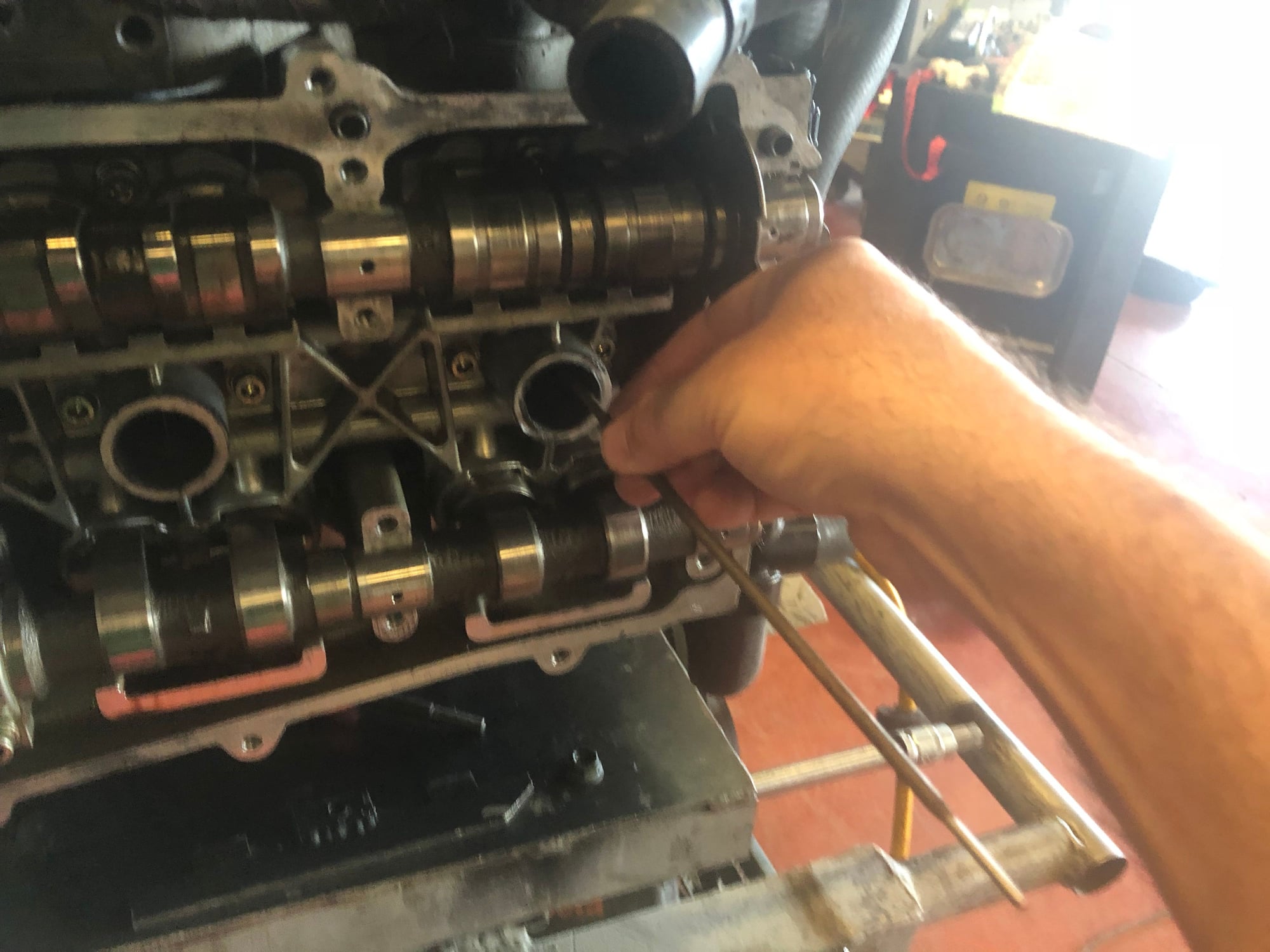
After installing the cams and chains with tensioners (do the chains have to be installed in any special way regarding positioning marks or anything as the book doesn't say anything or at least I haven't seen it) with the crankshaft pulley locked at U6. I am then positioning the intake and exhaust cam lobes for cylinder 4 facing each other and the slots on the end of the camshafts straight to be able to insert the locking tool (see pics)
Cam lobes at cyl.4 pointing each other
Slots for camshaft positioning tool vertical at bank 4-6
I am then installing the exhaust cam sprocket and leaving the holes in the most clockwise position with no bolts as the book states, then installing the camshaft positioning tool and then rotating the crankshaft pulley to TDC. As the book states the four M6 bolts that hold the exhaust cam sprocket are in the center of the slots, and I am tightening them as well as the big bolt for the intake cam. Then I am removing the camshaft positioning tool, turning the crankshaft pulley clockwise to mark U6 again, locking there and then repeating procedure again for banks 1-3 at cylinder 1 but as the book says, with the cam lobes pointing away from each other:
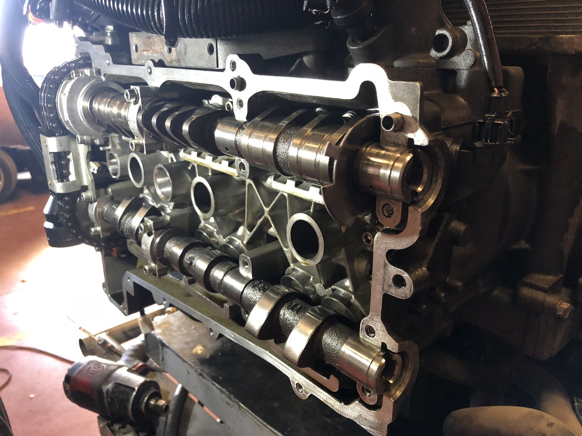
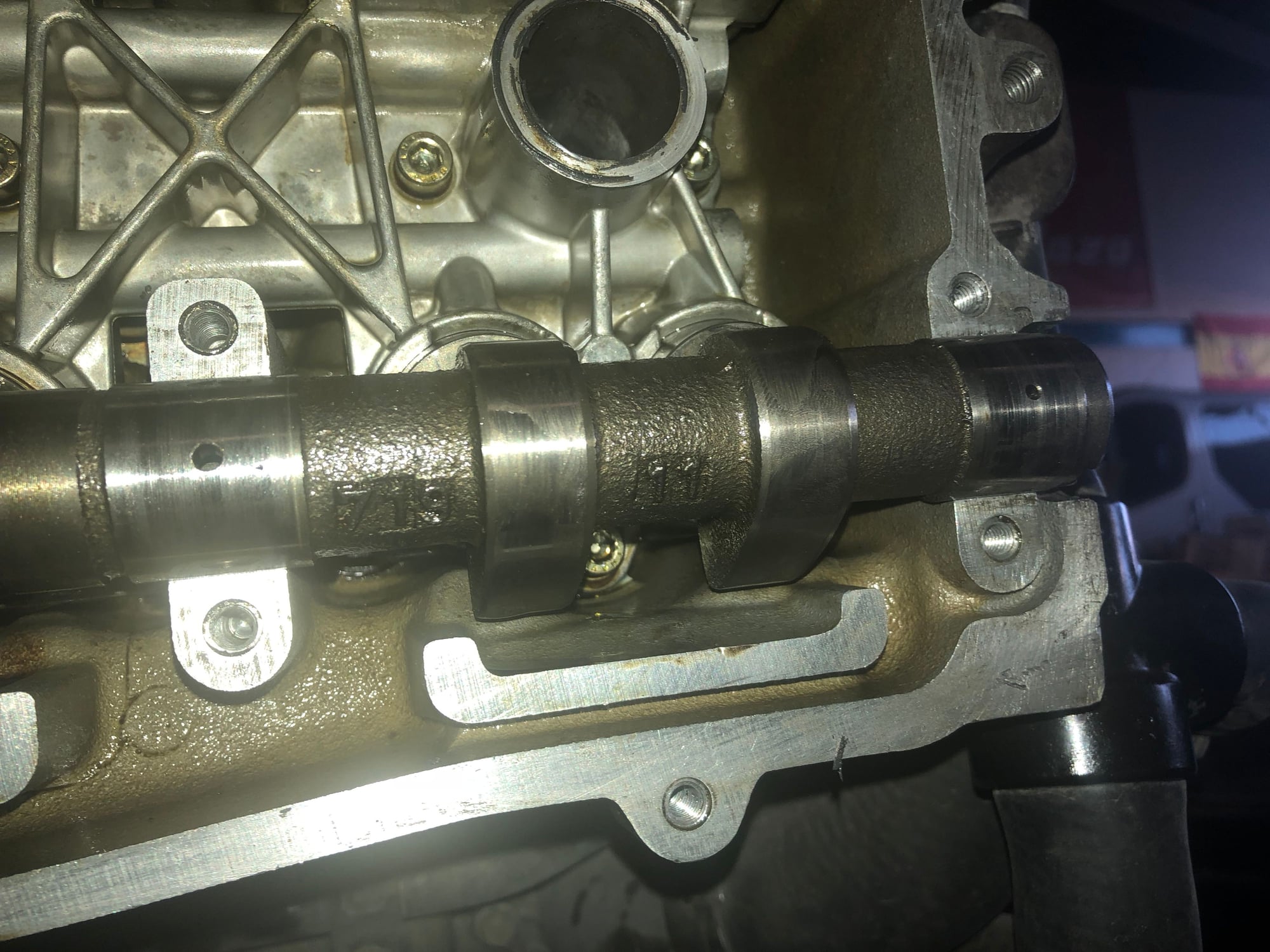
Cam lobes at cyl.1 facing away from each other (although exhaust lobes can't really be seen in the pic it is facind down)
Slots at the end of cams vertically to insert cam positioning tool
I am then torquening everything to spec and then removing cam positioning tool and crank locking tool to apply some logic turning the engine to see if it is kind of right...
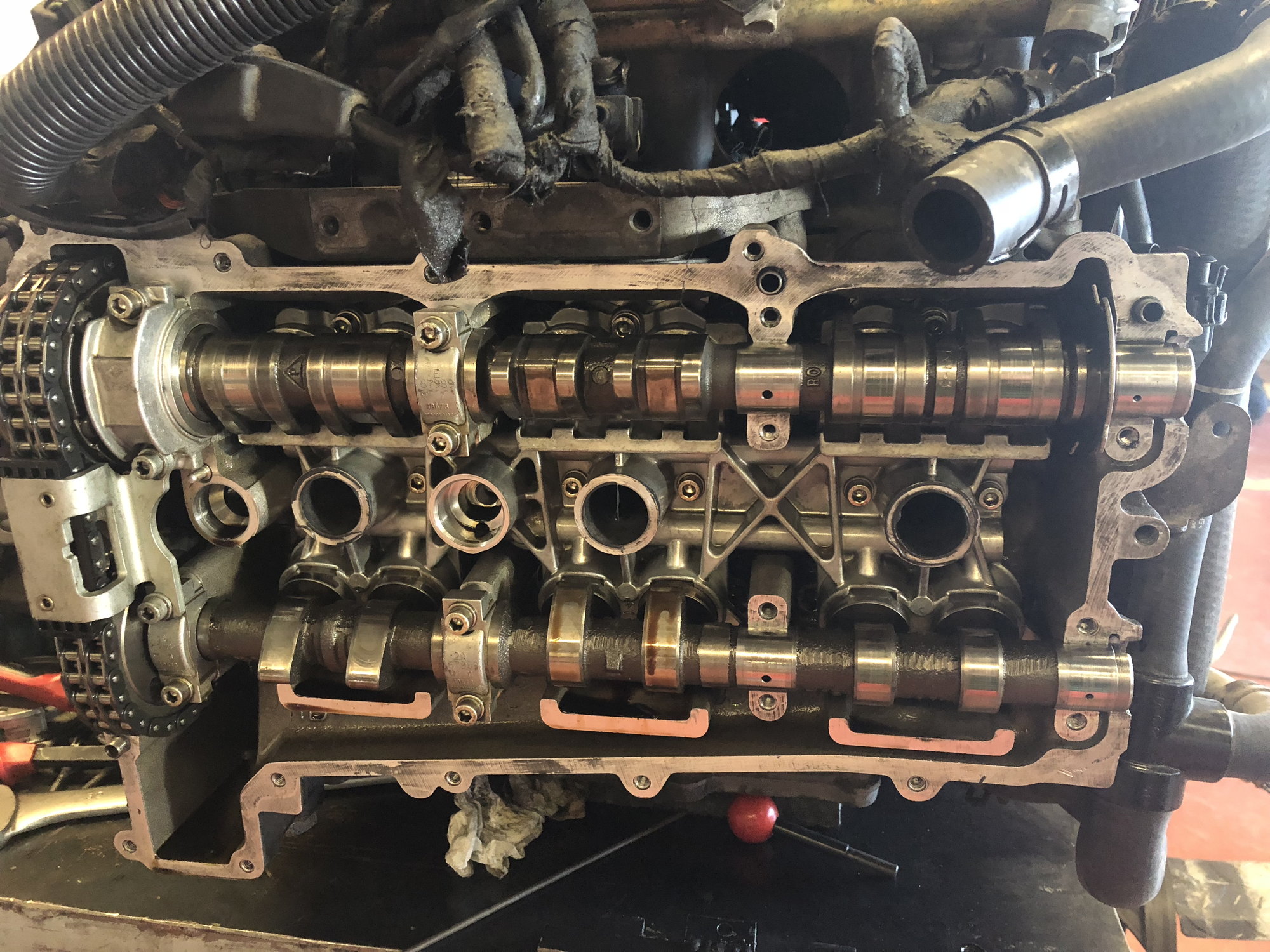
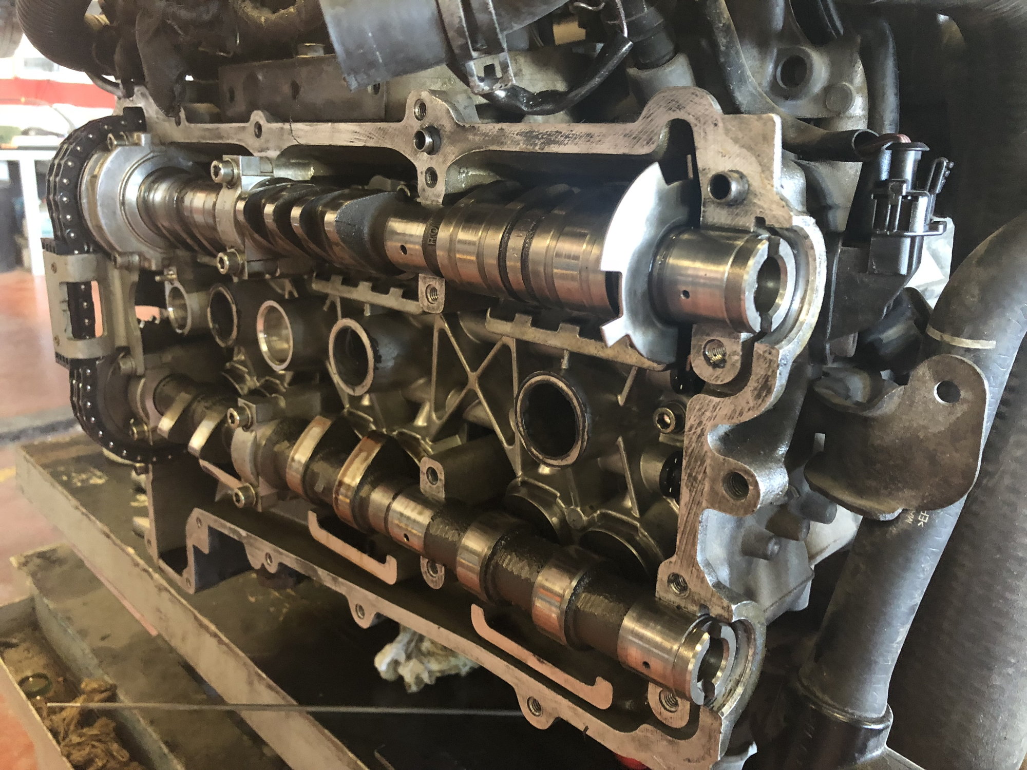
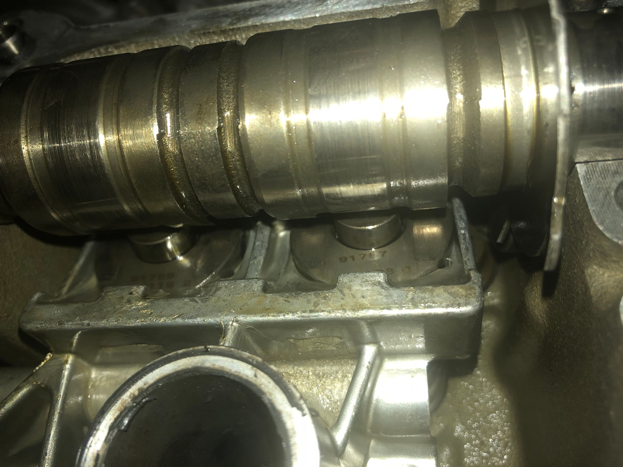
And the truth is that I am doing something wrong as when checking cylinders at TDC, my logic says exhaust lobes should be pretty near their tappets to push them and open the exhaust valves, and the truth is that they are way off there, in this pic, cyl.1 is at TDC and the exhaust lobes just passed their tappets and intake lobes are pushing their tappets NOT RIGHT.
Cylinder 1 at TDC
With cyl.1 at TDC exhaust cam lobes just passed their tappets?!?
With cyl.1 at TDC intake cam lobes are pushing their tappets?!?
Can anyone please point what I am doing wrong or direct me to a guide for complete idiots with pics if possible...
Thanks in advance everyone and sorry for the long thread
Sounds about right. Check if you have compression in the cylinder in the firing order 1-6-2-4-3-5 to verify course timing. Then use the cam locking tool to verify the fine timing.
Now that I was writting my own explanation of what I did and looking at the book I realized there is something I did not really noticed and I don't really understand (I am a spaniard trying to follow a book written in another lenguaje...)
In step 34 of my book it says "...install the camshaft positioning tool (inset lower right, blue arrow)...
what does it mean with that inset lower right?
Also in step 35 when it says to install the bolt of the intake cam it says insert upper right, what does it mean by that??? I just noticed the intake cam is somewhat moved to the right with a yellow mark in the upper right... am I supposed to move the intake cam? But it is supposed to be loked in place by the camshaft positioning tool, doesn't it?
Last edited by me61ic; 07-31-2018 at 07:48 PM.
Reason: Copyright issues
Sounds right to me too...as long as the chain tensioners are being installed at some point....
There really isn't a lot of room for logic here. Follow the procedure, turn the engine a few times, and verify that the tools fit; first one side, then spin 360 degrees and check the other.
Sounds right to me too...as long as the chain tensioners are being installed at some point....
There really isn't a lot of room for logic here. Follow the procedure, turn the engine a few times, and verify that the tools fit; first one side, then spin 360 degrees and check the other.
Chain tensioners and change guide retaining bolt were not removed as we considered that was not necessary as the cams can move freely when they are without their bolts attaching them to their sprockets. Am I right or is this a mistake?
Chain tensioners and change guide retaining bolt were not removed as we considered that was not necessary as the cams can move freely when they are without their bolts attaching them to their sprockets. Am I right or is this a mistake?
As long as the tensioners were installed before you set timing, you are good.
I just re-read your original post - I see now - sounds good.
I am going to try and do everything from the beginning again tomorrow evening step by step. I just went through all the steps again here at home to see I understand everything correctly and just realized that when the engine is moving, for one full cycle of the crankshaft the camshafts have done half a cycle, so cylinders 1 & 4 are at TDC, but one of them (say for instance number 4) will be in the compression/ignition phase of the 4 strokes and the other (cyl. 1 in that case) overlapping, and when the crankshaft rotates another full cycle, the opposite (in that case number 1) will be in the compression/ignition phase of the 4 strokes and the other (number 4) overlapping, so I just have to check logic of phases for 4 strokes for 3 cylinders in one cycle of the crankshaft (for instance 4-3-5) and the other 3 cylinders in the next cycle (1-6-2 in my example.
Right?
I really want to go through with the logic before reinstalling the engine in the car, as I want to make sure everything is ok before all the work that takes installing the engine again, and also as I don't want catastrophic consequences of not doing the timing properly.
You got it. Be careful is great. If you don't want a redo, just do the test I mtioned to verify compression and make sure the cam locking tool fits both banks alternately as you keep rotating the cranks for more turns.
At TDC when the cam locking tool fits, the cyl (1 or 4) on that bank is at overlap.
I have to redo everything, as when things were not having logic in my head (my physical human head), I started trying different things like having the lobes for cyl.4 looking at each other and cyl. 1 away from each other at the same time without rotating the engine a whole cycle. Now that I understand what is going on, I prefer to start from the beginning as I don't really remember where I left it, and was not using the new bolts or torquing to spec either.
By the way that book does not say the torque specs for bolts, I was going to look for them after checking that everything was right but if any of you could give them if you know them I would be most grateful.
Again, many, many thanks for all the help, you guys are the best
I just went through this and agree that the 101 isn't 100% clear, have a look at the below thread on mine, you will see pics of Bank 1 and 2 from the following:
1. Bank 1 Cy1 at TDC, crank pinned, cam locking tool in place (if the locking tool doesn't fit rotate crank 360. Follow the thread and there is a pic of the cam orientation.
2. After refitting Bank 1, rotate crank 360 and pin, fit cam locking tool. Again in the thread there is a pic of the cam orientation
Let me know if that makes sense, I was a bit worried about mine as I seem to remember bank 2 cams felt like they were under valve pressure and I missed something. but it worked and 1,000 miles later it still works.
Thanks everything helps. Good reading on your thread 👍
 07-30-2018, 08:02 PM