

removing rear suspension


 11-06-2011, 06:35 AM
#92
Racer
Thread Starter
Join Date: Apr 2009
Location: London
Posts: 427
Likes: 0
Received 0 Likes
on
0 Posts
RS REAR SUSPENSION
Rear upper crossmember freshly powder coated
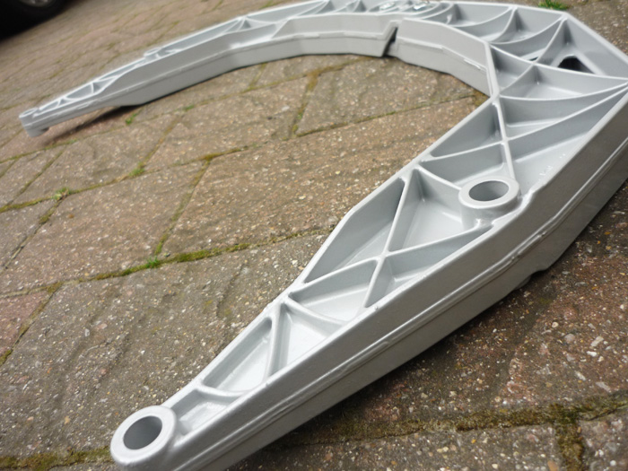
Up it goes. Two M10's at 65nm
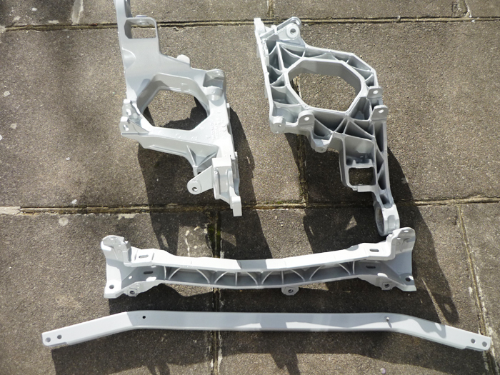
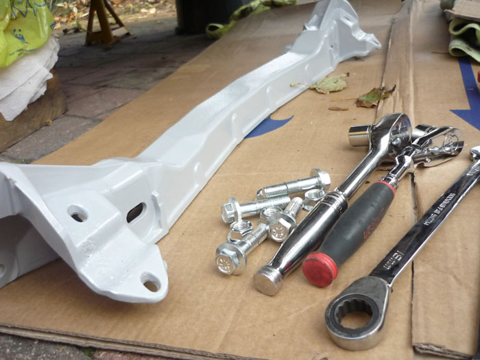
Two side sections, front and rear lower crossmembers.... freshly blasted and powder coated of course. Read more about my powder cotaing antics here.
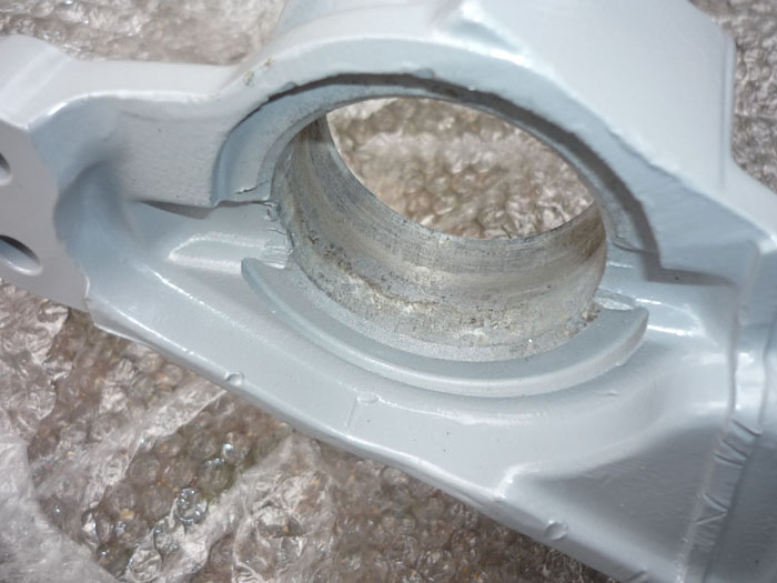
I gave the bush mount surfaces a bit of a file or rub with wet and dry to smooth down and remove any corrosion.
A little Dinitrol on the new Rennline solid mounts.
And some FK1000p sealant on the whole side section to give it better protection from the wet.
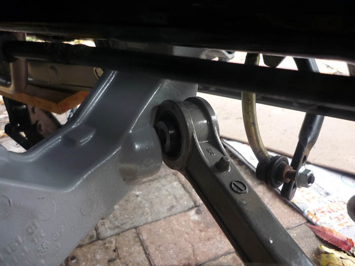
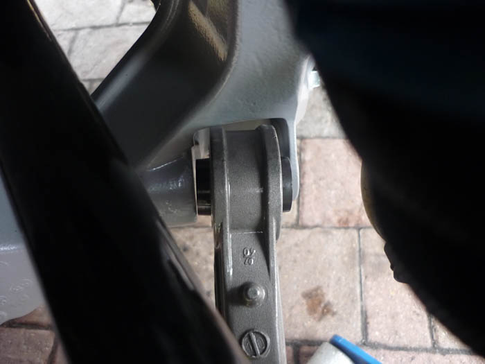
Rennline solid bushes in.
And here's how they look from the top with a spacer at each end.
Installed. Use the Rennline supplied bolts that are the new correct length and tighten to 120nm. You will see that the whole of the side section is now raised up compared to how it was. This means that the whole rear suspension cage will be a little it higher. This is because Rennline copied the porsche race GT2 EVO bushes. It means that at any given ride height the rest geometry or the angles of the suspension arms with respect to the horizontal will have changed. This effect is much like what happens at the front with the RS uprights. At RS ride height the rear arms won't be poiting up so much and will be more level when at rest. I would imagine that this will give better bumpsteer and rear kinematic toe profiles.
I know that the oem facory RS side sections are different from stock. I know that the hardness of those bushes is stiffer and I also know that they have a different camber slot to allow for a wider range of camber. But what I'm not sure about is the height of the bushes. Maybe they are also a little less tall and also pull the side sections up to the chassis a bit more ? That would certainly make sense if they did. There is more to lowering a car than just dropping the platforms and one would imagine that Porsche also did something to reset the rest geometry of the multilinks. If Rennline did copy the sizes of the Race GT2 EVO mounts then certainly, the race cars had their rear suspension cages raised.
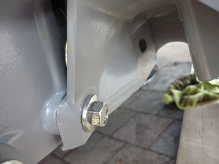
This actually isn't done up tight yet. You can see my seam this side is quite thick and I did get a bit of rubbing. Clearance is tight.
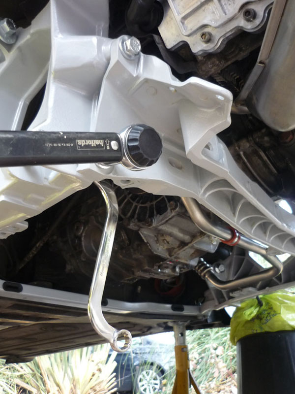
You can now bolt the upper crossmember to the side sections. Two M12's either side at 85nm. Looking up here at both bolts.
And looking across at just the lower one.
Now onto the rearmost crossmember with some newly plated screws. These want 120nm.
Complete both sides with all screws and eccentrics in place.
Back to the control arms. I am effectively making my own rear RS supension the cheap way. This involves rebushing the kinematic toe arms and the trailing bush in the lower A arm, both to harder RS spec rubber. This is all that Porsche does except they charge you millions per arm whereas elephant racing products in the USA charge $50 a bush and the press I own already.
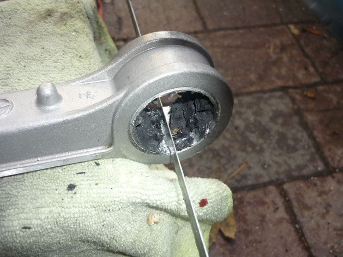
My method is to start by drilling through the rubber of the old bush. An airsaw would be MUCH easier and quicker but I don't have one and the shops were closed.
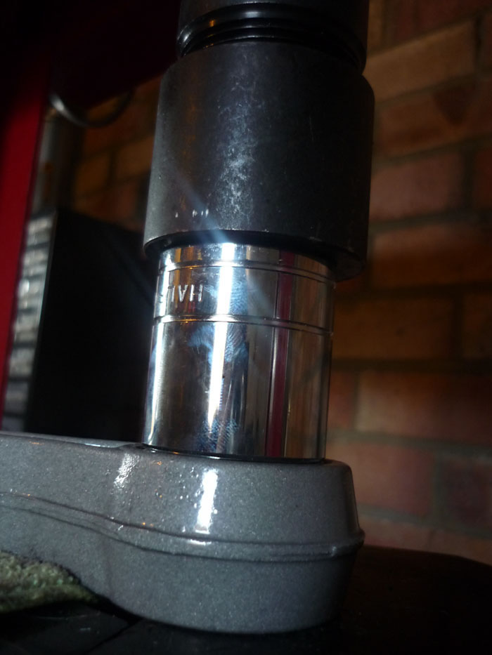
I then press the old middle piece out using a socket.
You'll have a rubbery mess there but find a clear space and then get a hacksaw blade in and cut a slot back to the actual alloy. Not too deep, it only needs a few swipes with a decent blade.
Ready to roll.
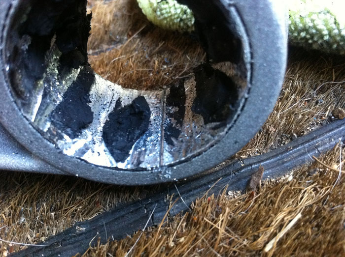
You can start chipping away near the cut. You want to chip inwards and then also away from the slot on both sides.

I tend to use an air chisel which is many many times easier.
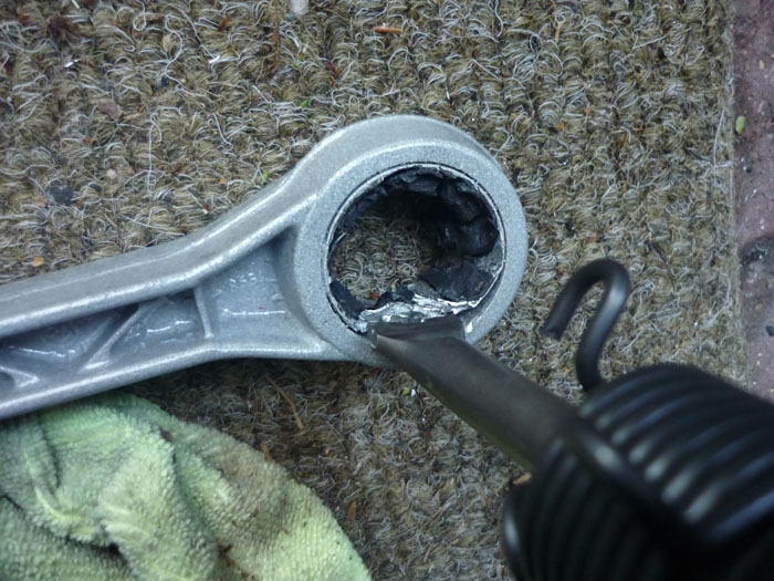
A couple of squirts of the air chisel and then you are good to go .. it will come out very easily.
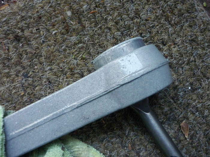
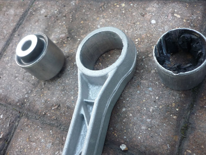
New shure 85 bush, empty arm, old bush
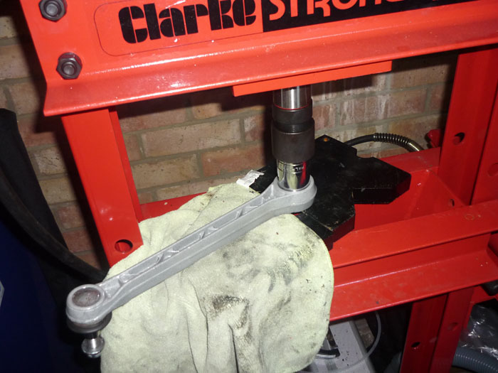
I press in the new sport bushes with a perfect sized socket.
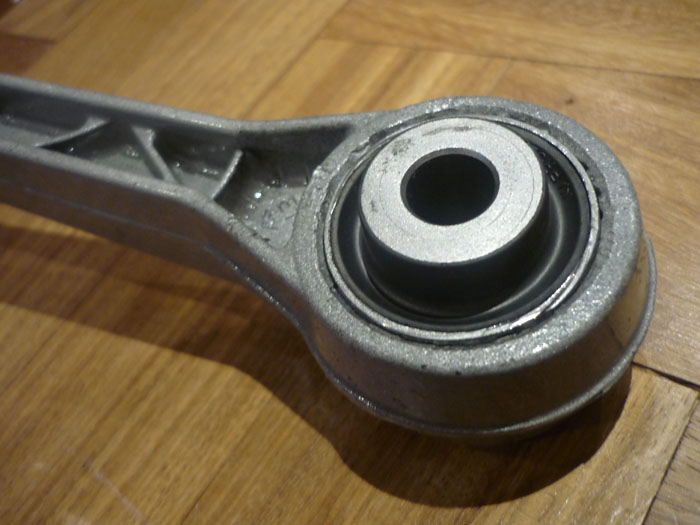
Voila.
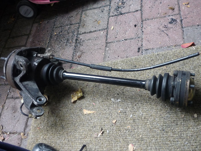
A quick clean of the driveshafts and CV boots.
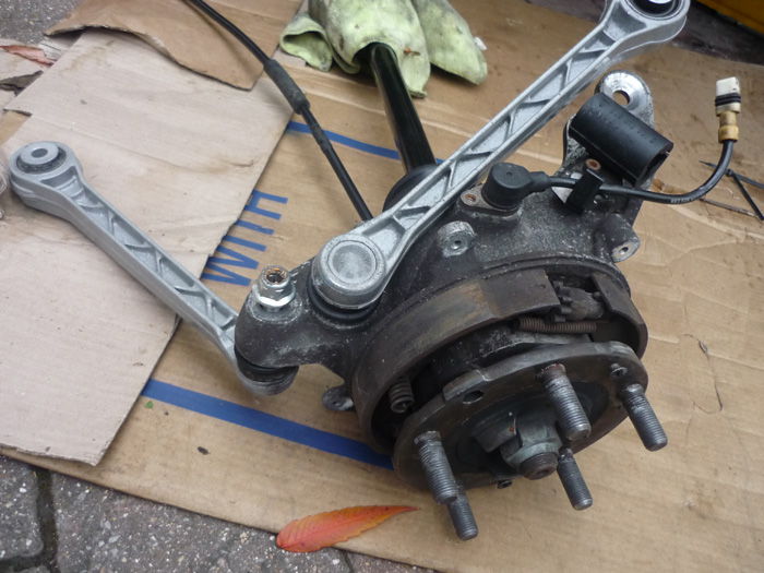
I found that the best method for getting the uprights on was to fit the upper camer and kinematic/caster arms first.
Counter hold them with a Torx driver and tighten to 75nm.
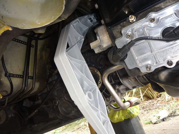
Fit your lower toe arm to the rear crossmember. You may need raise the engine for the nearside so that the eccentric bolt can clear the heat exchanger. On the offiside you may just need to raise yuor anti roll bar to get the eccentric in.
Now grab the upright and thread the driveshaft and handbrake cable through the middle of the side section.
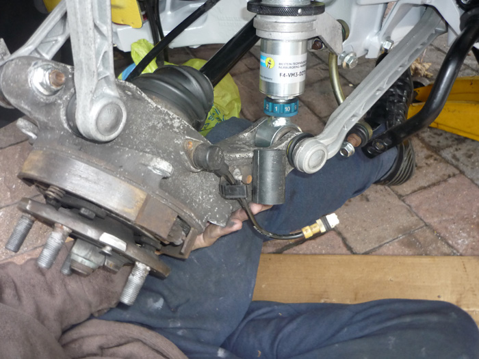
Now lift the whole upright forward and get teh lower connection into the end of the damper body and with your free hand force the end of teh toe arm through.
Now you can hold both arms and guide them both at the same time into their slots.
Note that if you fit the upright to the damper and lower A arm first and then try and fit both upper arms onto upright and side sections you won't be able to. That's why its best to fit the upper arms to the upright whilst off the car.
One side done.. just lacking the lower A arm. Do NOT tighten anything yet.
To get the A arm in roughly positin it, making sure the leading monoball is in its slot.
The trailing bush will sort of lok like this. It won't go in as the arm is still at slightly too much of an angle.
Looking top down you can see that angle a bit better. You just need a few hits with a mallet though and it will go in.
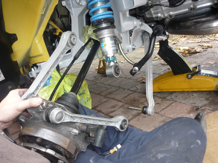
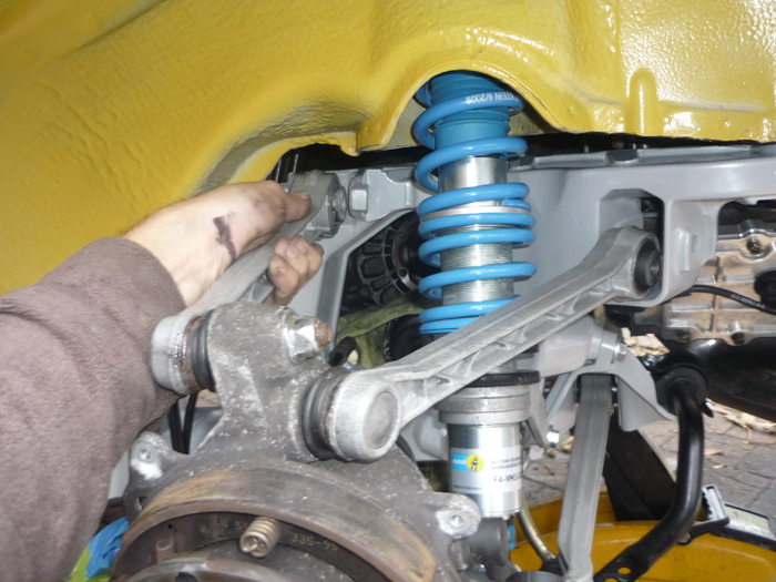
Now everything's in you can think about tightening it all up. Not like this though.
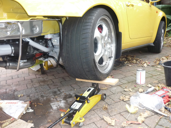
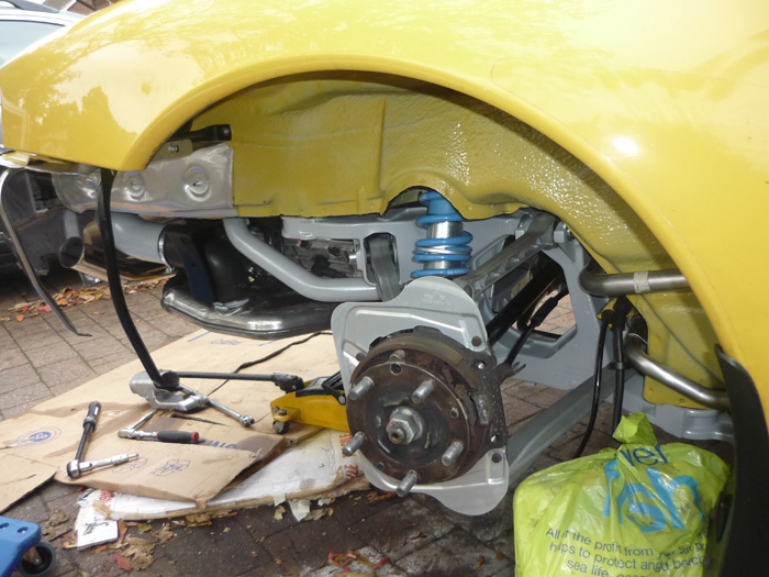
To tighten up most of it you'll want to first raise the upright to the regular ride height of the car. Its easier to judge this with a wheel on of course and then jack it up and use the wheelarch/tyre gap as an indication of your approximate ride height.
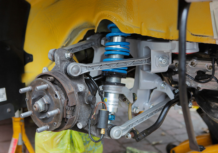
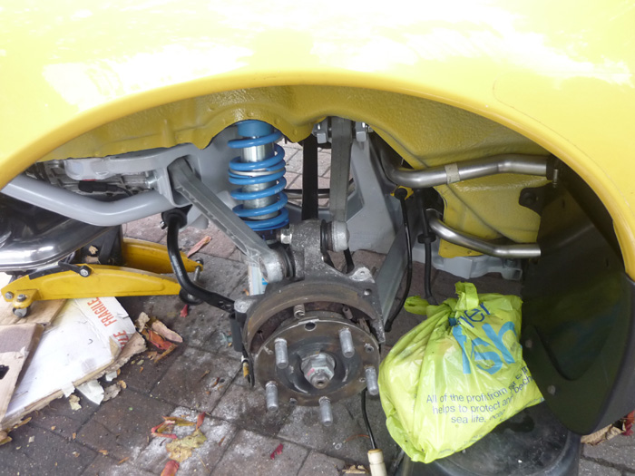
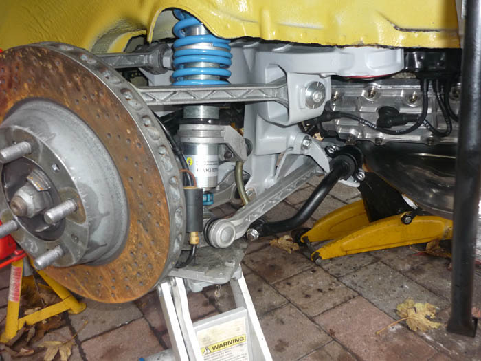
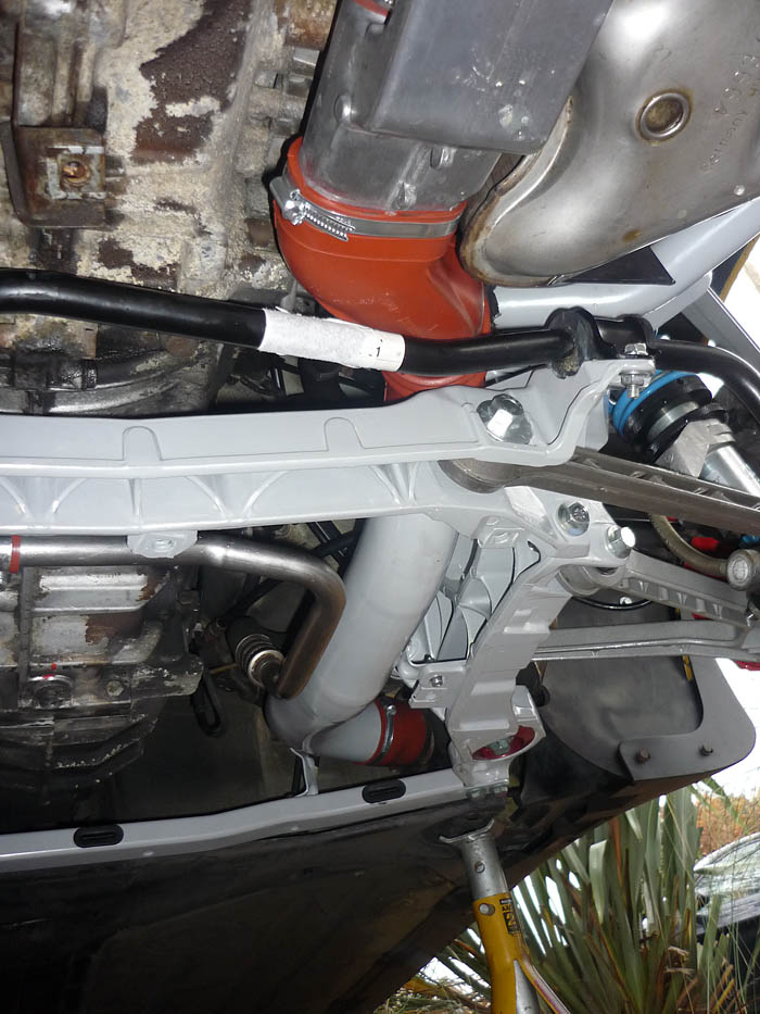
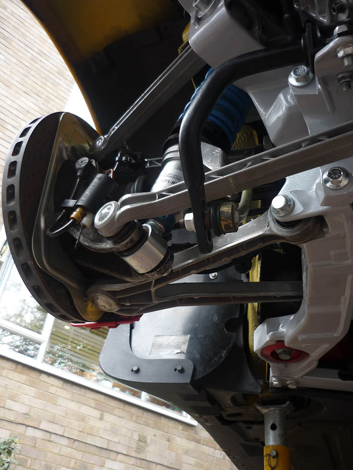
Here's a back view of all the arms and their angles with the tyre at its RS height.
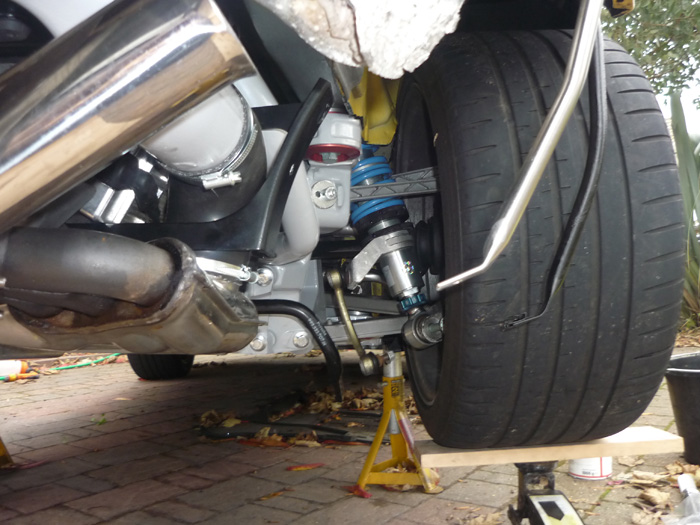
Because the arms are now all roughly at rest angle you can NOW tighten up anything that goes through a bush. If you don't do this and tighten everything with the suspension effectively at full droop then when the car is back on the road and sitting most of the time at or around your proper ride height, all the bushes will be under a torsional load or twisted from the position that they were tightened up. This is not something you want.
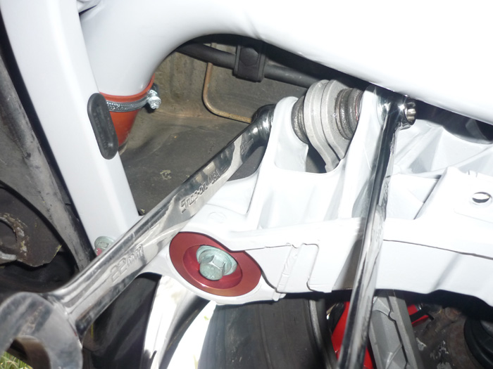
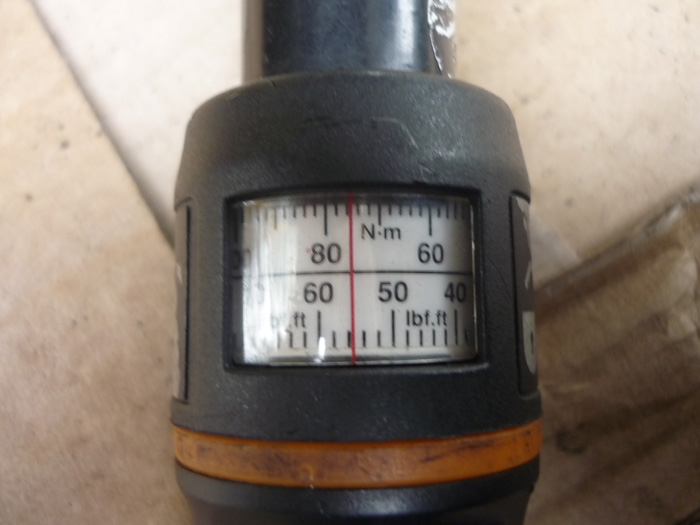
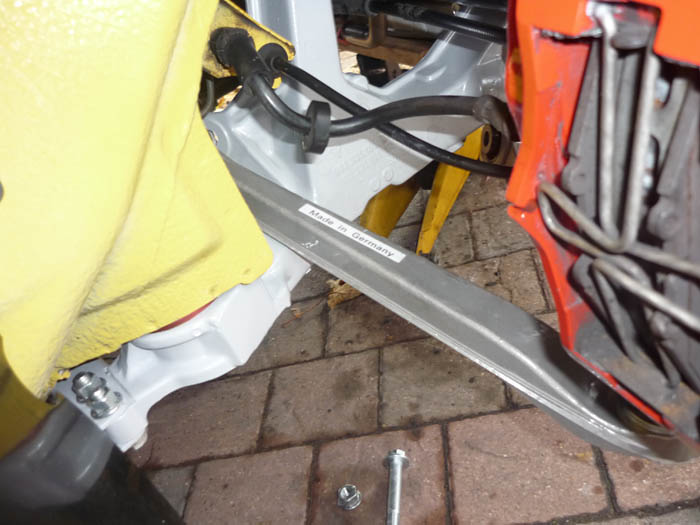
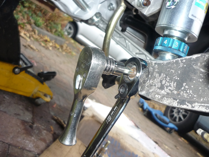
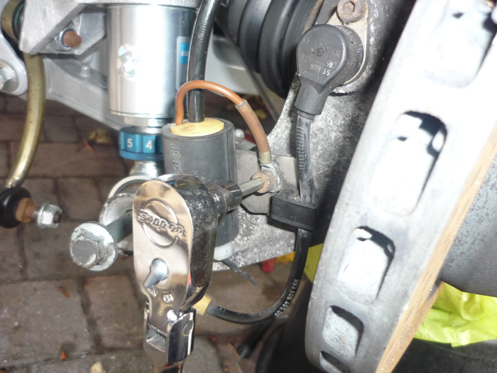
Here we are at the leading lower A arm link which is actually a monoball. This wants 200nm, 22mm and 19mm spanners from memory... its a bit of a bitch so take your time and try not to get angry and shout lots like I did ! To be honest I found my torque wrench became a bit sketchy here. I would hit say 180nm and the wrench would click but then on another pull I could tighten it another 180 degrees or something. I became a bit distrustful of it and will get it checked when I get my geometry done. Suffuce to say that it is fr***in tight for the meantime.
The trailing bolt on the lower arm is much more straightforward and tightened to 85nm with 18 and 19 spanners.
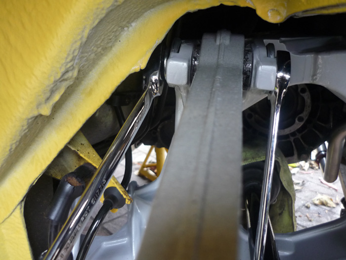
Here's the camber arm. 18 and 19mm spanners. 85nm
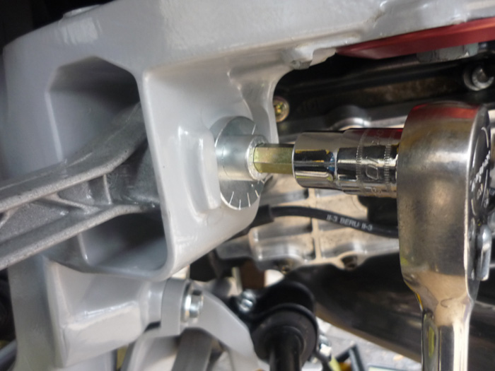
The Kine toe or caster arm is a hex head and is already counterheld with a captive nut in a bracket the other side. It also wants 85nm.
The outboard end of the lower toe arm which goes through the upright. DON'T FORGET TO COUNTERHOLD with a torx. Many a toe arm boots have been unecessarily split because of this. 85nm please.
Don't forget to tighten the rear anti roll bar to the droplinks and also to the crossmember... whilst the upright is raised to proper ride height.
All done with some new cover protection plates for good measure.
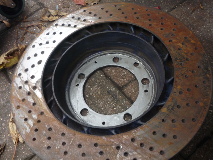
Brake discs given a little anti rust and some optymoly on the rear faces that will mate with the hub carriers.
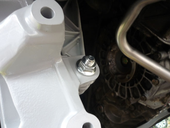
Clip your abs lead back into the connector and the connector back into its bracket. The ground wire into the cap head, a little copperslip and tighten/
Rear upper crossmember freshly powder coated
Up it goes. Two M10's at 65nm
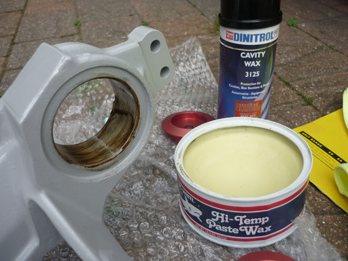
Two side sections, front and rear lower crossmembers.... freshly blasted and powder coated of course. Read more about my powder cotaing antics here.
I gave the bush mount surfaces a bit of a file or rub with wet and dry to smooth down and remove any corrosion.
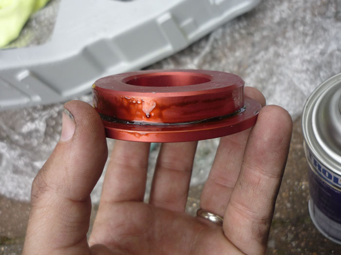
A little Dinitrol on the new Rennline solid mounts.
And some FK1000p sealant on the whole side section to give it better protection from the wet.
Rennline solid bushes in.
And here's how they look from the top with a spacer at each end.
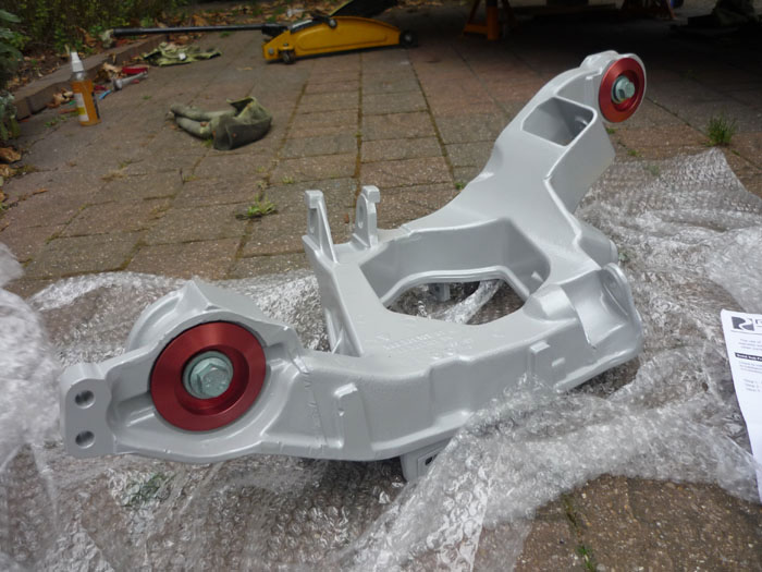
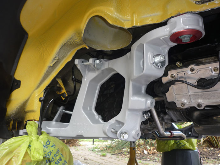
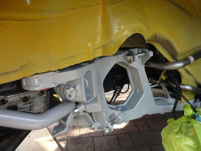
Installed. Use the Rennline supplied bolts that are the new correct length and tighten to 120nm. You will see that the whole of the side section is now raised up compared to how it was. This means that the whole rear suspension cage will be a little it higher. This is because Rennline copied the porsche race GT2 EVO bushes. It means that at any given ride height the rest geometry or the angles of the suspension arms with respect to the horizontal will have changed. This effect is much like what happens at the front with the RS uprights. At RS ride height the rear arms won't be poiting up so much and will be more level when at rest. I would imagine that this will give better bumpsteer and rear kinematic toe profiles.
I know that the oem facory RS side sections are different from stock. I know that the hardness of those bushes is stiffer and I also know that they have a different camber slot to allow for a wider range of camber. But what I'm not sure about is the height of the bushes. Maybe they are also a little less tall and also pull the side sections up to the chassis a bit more ? That would certainly make sense if they did. There is more to lowering a car than just dropping the platforms and one would imagine that Porsche also did something to reset the rest geometry of the multilinks. If Rennline did copy the sizes of the Race GT2 EVO mounts then certainly, the race cars had their rear suspension cages raised.
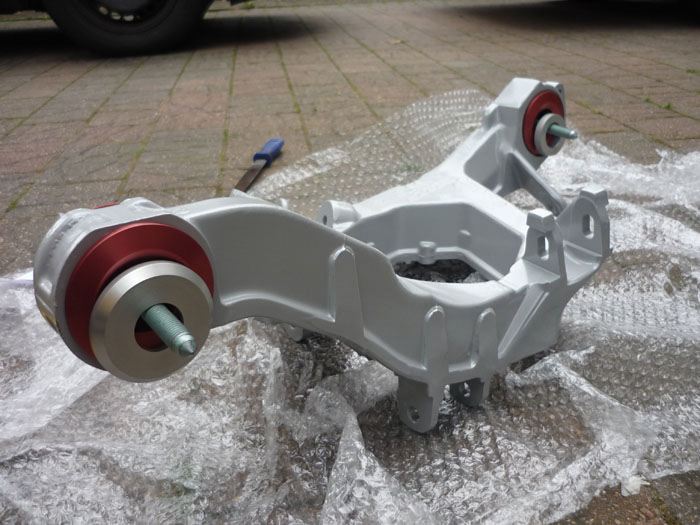
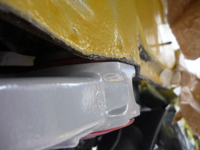
This actually isn't done up tight yet. You can see my seam this side is quite thick and I did get a bit of rubbing. Clearance is tight.
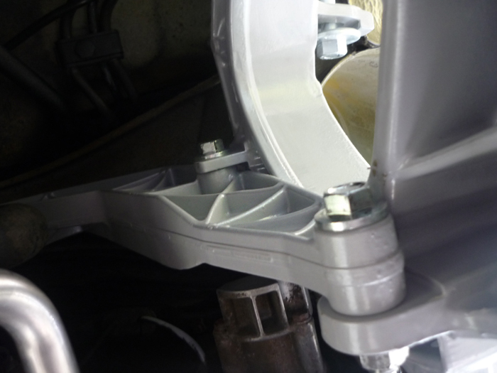
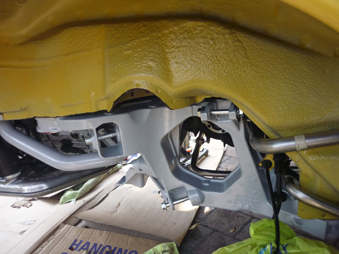
You can now bolt the upper crossmember to the side sections. Two M12's either side at 85nm. Looking up here at both bolts.
And looking across at just the lower one.
Now onto the rearmost crossmember with some newly plated screws. These want 120nm.
Complete both sides with all screws and eccentrics in place.
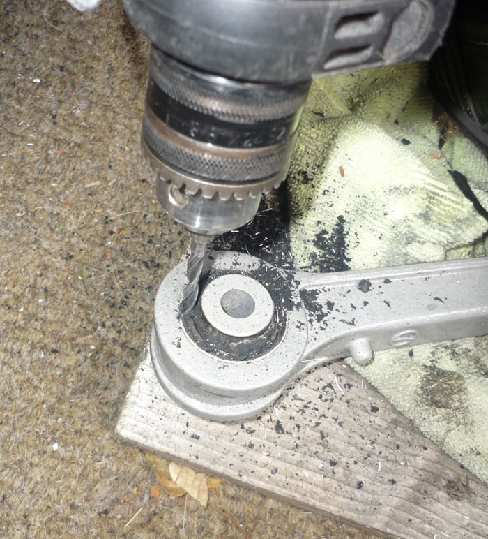
Back to the control arms. I am effectively making my own rear RS supension the cheap way. This involves rebushing the kinematic toe arms and the trailing bush in the lower A arm, both to harder RS spec rubber. This is all that Porsche does except they charge you millions per arm whereas elephant racing products in the USA charge $50 a bush and the press I own already.
My method is to start by drilling through the rubber of the old bush. An airsaw would be MUCH easier and quicker but I don't have one and the shops were closed.
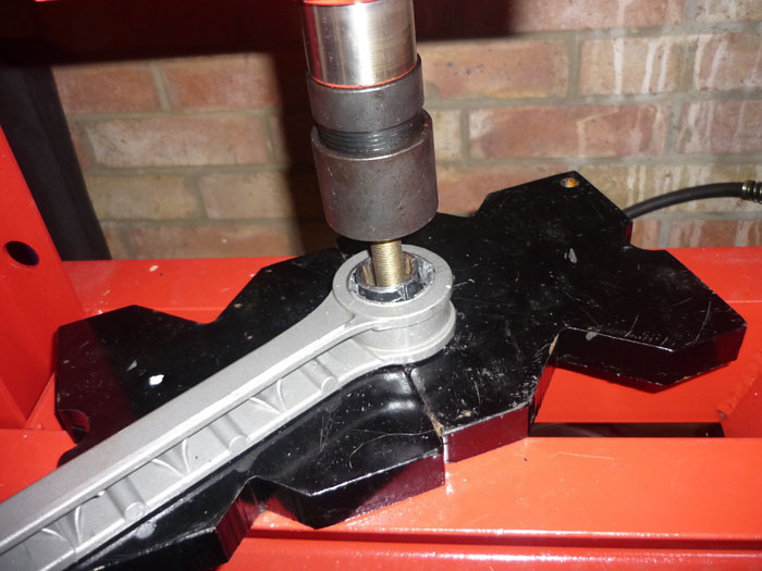
I then press the old middle piece out using a socket.
You'll have a rubbery mess there but find a clear space and then get a hacksaw blade in and cut a slot back to the actual alloy. Not too deep, it only needs a few swipes with a decent blade.
Ready to roll.
You can start chipping away near the cut. You want to chip inwards and then also away from the slot on both sides.
I tend to use an air chisel which is many many times easier.
A couple of squirts of the air chisel and then you are good to go .. it will come out very easily.
New shure 85 bush, empty arm, old bush
I press in the new sport bushes with a perfect sized socket.
Voila.
A quick clean of the driveshafts and CV boots.
I found that the best method for getting the uprights on was to fit the upper camer and kinematic/caster arms first.
Counter hold them with a Torx driver and tighten to 75nm.
Fit your lower toe arm to the rear crossmember. You may need raise the engine for the nearside so that the eccentric bolt can clear the heat exchanger. On the offiside you may just need to raise yuor anti roll bar to get the eccentric in.
Now grab the upright and thread the driveshaft and handbrake cable through the middle of the side section.
Now lift the whole upright forward and get teh lower connection into the end of the damper body and with your free hand force the end of teh toe arm through.
Now you can hold both arms and guide them both at the same time into their slots.
Note that if you fit the upright to the damper and lower A arm first and then try and fit both upper arms onto upright and side sections you won't be able to. That's why its best to fit the upper arms to the upright whilst off the car.
One side done.. just lacking the lower A arm. Do NOT tighten anything yet.
To get the A arm in roughly positin it, making sure the leading monoball is in its slot.
The trailing bush will sort of lok like this. It won't go in as the arm is still at slightly too much of an angle.
Looking top down you can see that angle a bit better. You just need a few hits with a mallet though and it will go in.
Now everything's in you can think about tightening it all up. Not like this though.
To tighten up most of it you'll want to first raise the upright to the regular ride height of the car. Its easier to judge this with a wheel on of course and then jack it up and use the wheelarch/tyre gap as an indication of your approximate ride height.
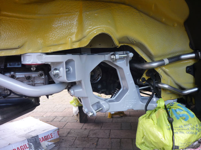
Here's a back view of all the arms and their angles with the tyre at its RS height.
Because the arms are now all roughly at rest angle you can NOW tighten up anything that goes through a bush. If you don't do this and tighten everything with the suspension effectively at full droop then when the car is back on the road and sitting most of the time at or around your proper ride height, all the bushes will be under a torsional load or twisted from the position that they were tightened up. This is not something you want.
Here we are at the leading lower A arm link which is actually a monoball. This wants 200nm, 22mm and 19mm spanners from memory... its a bit of a bitch so take your time and try not to get angry and shout lots like I did ! To be honest I found my torque wrench became a bit sketchy here. I would hit say 180nm and the wrench would click but then on another pull I could tighten it another 180 degrees or something. I became a bit distrustful of it and will get it checked when I get my geometry done. Suffuce to say that it is fr***in tight for the meantime.
The trailing bolt on the lower arm is much more straightforward and tightened to 85nm with 18 and 19 spanners.
Here's the camber arm. 18 and 19mm spanners. 85nm
The Kine toe or caster arm is a hex head and is already counterheld with a captive nut in a bracket the other side. It also wants 85nm.
The outboard end of the lower toe arm which goes through the upright. DON'T FORGET TO COUNTERHOLD with a torx. Many a toe arm boots have been unecessarily split because of this. 85nm please.
Don't forget to tighten the rear anti roll bar to the droplinks and also to the crossmember... whilst the upright is raised to proper ride height.
All done with some new cover protection plates for good measure.
Brake discs given a little anti rust and some optymoly on the rear faces that will mate with the hub carriers.
Clip your abs lead back into the connector and the connector back into its bracket. The ground wire into the cap head, a little copperslip and tighten/
11-06-2011, 06:35 AM
#93
Racer
Thread Starter
Join Date: Apr 2009
Location: London
Posts: 427
Likes: 0
Received 0 Likes
on
0 Posts
The driveshaft flanges can go on now. 81nm
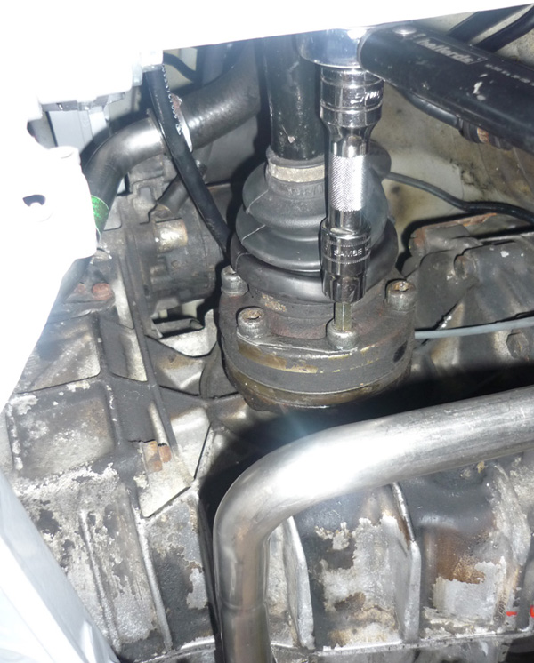
As the car is off the ground and the handbrake cable is disconnected, I use a breaker bar in between the wheel studs to stop the rotation.
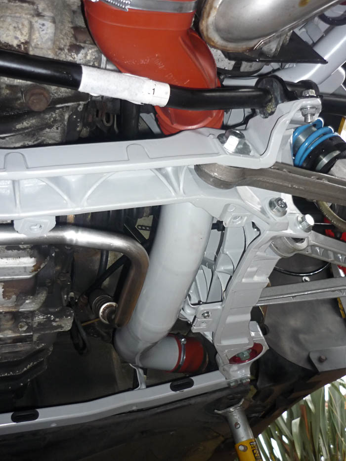
Heater pipes, heater flap and hoses go back in the way they came out.
That pretty much concludes the RS suspension at the rear. I will write up my impressions when its all together and the geometry is done and I have given it a good drive.
As the car is off the ground and the handbrake cable is disconnected, I use a breaker bar in between the wheel studs to stop the rotation.
Heater pipes, heater flap and hoses go back in the way they came out.
That pretty much concludes the RS suspension at the rear. I will write up my impressions when its all together and the geometry is done and I have given it a good drive.
11-06-2011, 06:52 AM
#94
Racer
Thread Starter
Join Date: Apr 2009
Location: London
Posts: 427
Likes: 0
Received 0 Likes
on
0 Posts
FINAL COSMETIC STUFF

Dinitrol applied to vunerable areas and any rust spots that have been treated with a chemical rust remover.
Ditto
Protection inside of the rear wings.
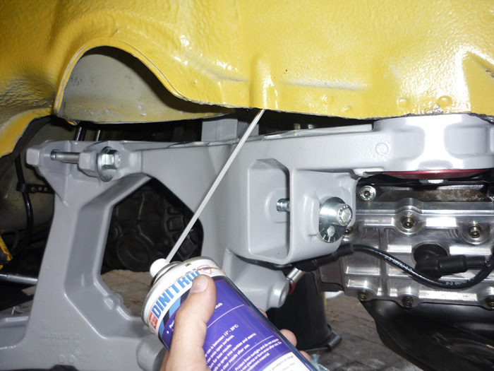
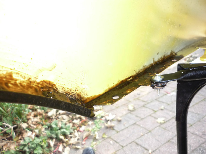
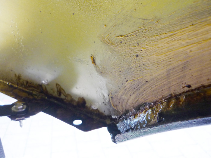
Dinitrol fired up into cavities and seams.
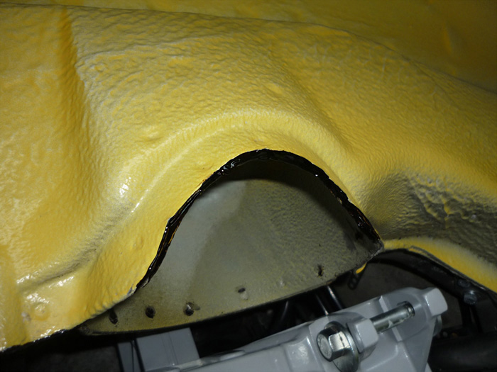
And a bead of dinitrol along the suspeension turret pinch seam.
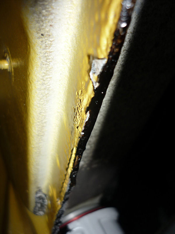
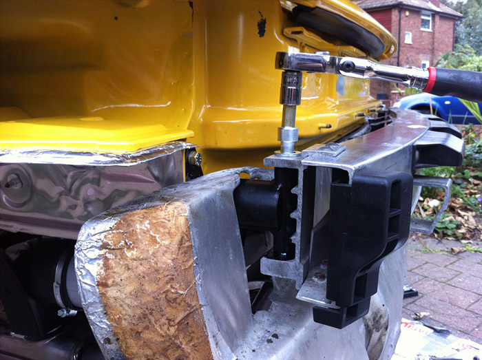
Now onto fixing that large heatshield. You can see that corrosion has got to the parts that are supposed to affix it to the rear pu. A common fix for this is metal tape but I decided to fix this with sheet ali. I don't want this flapping about whilst I am driving but I certainly don't want to replace with a new one as the price is extortionate.
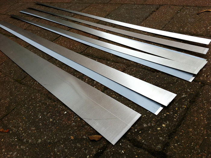
Strips of 1mm thick aluminium.
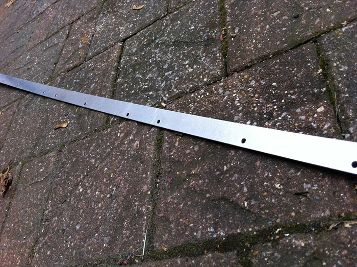
Holes drilled.
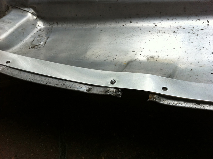
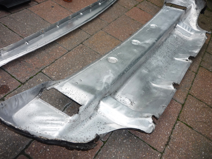
Pressed and formed over the big rear PU heatshield.
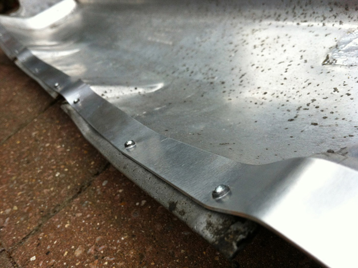
Riveted.
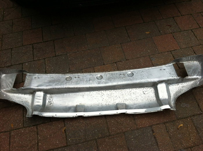
Voila, one heatshield that can now be properly fastened onto the PU.
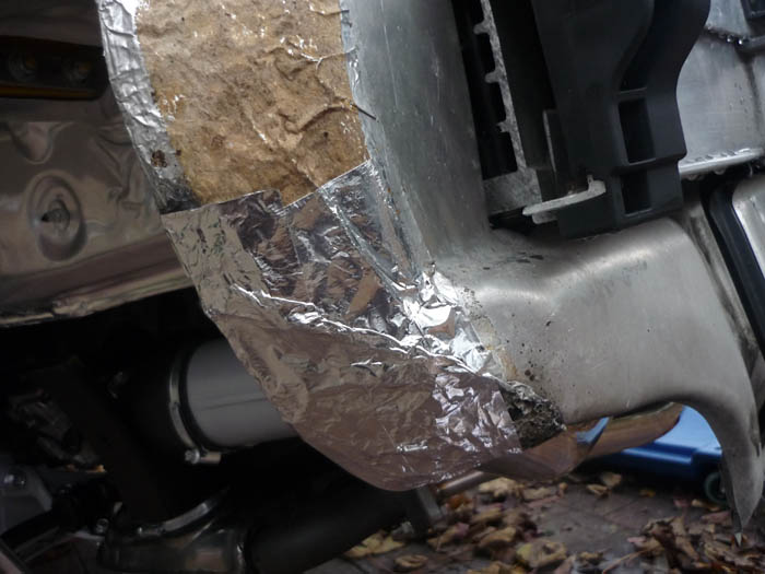
Main rear heatshield tidied up with metal tape.
Metal tape applied on the heatshield edge then wrapped under and up to the inside of the chassis leg so that a seal is formed and mud and dirt can't get in between these two. Time will tell how well this holds out.
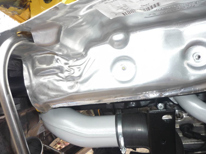
Back to the rear area. Dinitol applied on the faces of the bumper which will mate with the impact absorbers.
Tightened up.
Some dinitrol applied to the lower portion of these brackets where they engage with the rear PU. There was a LOT of corrosion on them when they came off.

new protective cover plates
heater tubes and hoses
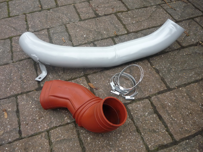
fitted
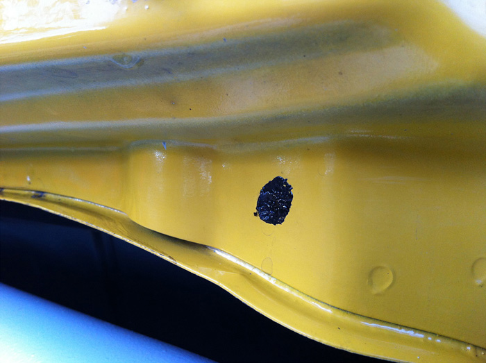
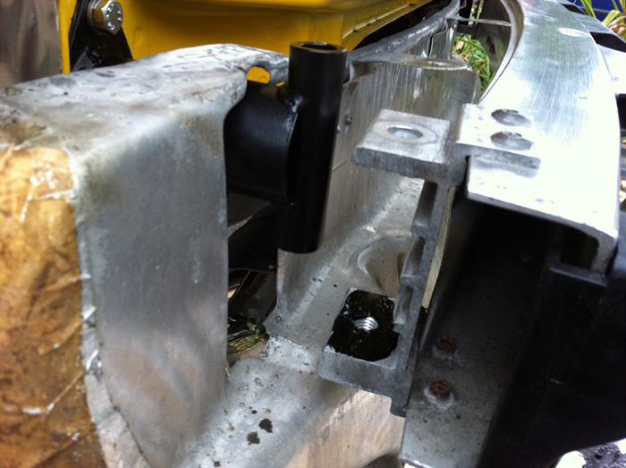
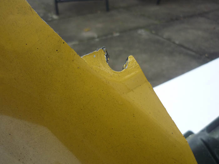
Bumper eyelet repair
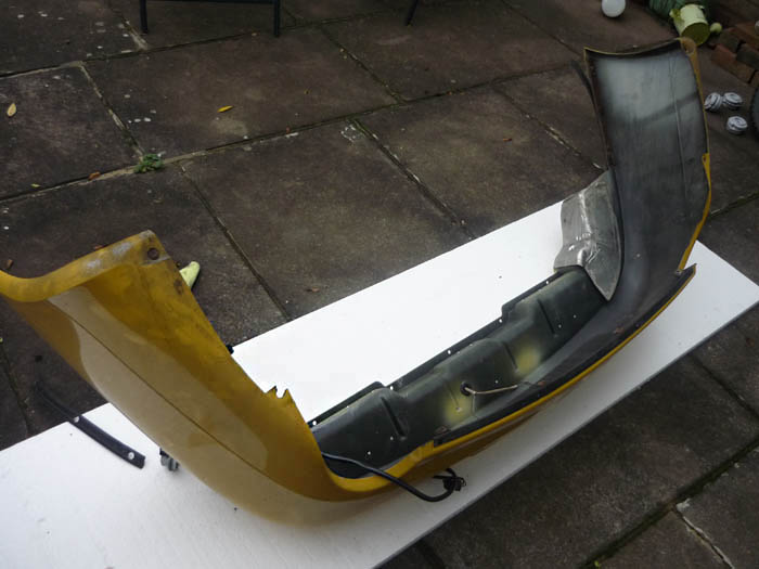
Here you can see the broken eyelet. The lower end of the rear bumper support is supposed to screw in here.
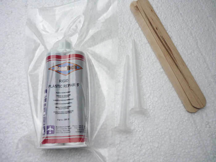
BONDTECH plastic repair expoxy. Available from ebay.
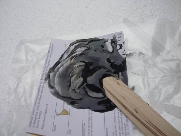
Mix some up.
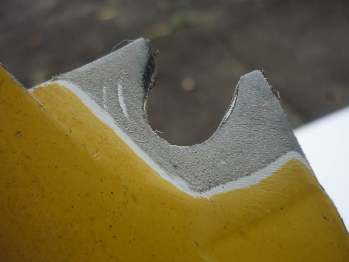
Prep the eyelet surfaces.
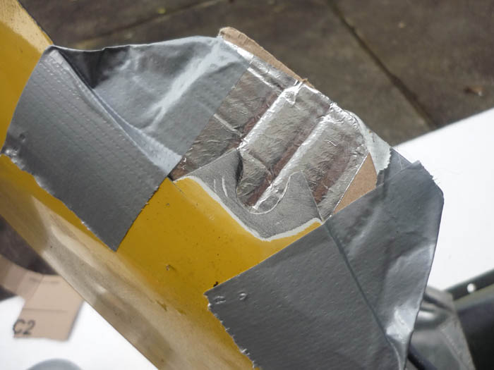
Fit some backing support (metal tape on a piece of cardboard in my case)
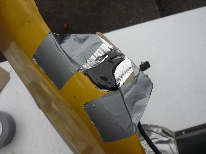
Build the epoxy up and allow to dry.
to be continued ...
Dinitrol applied to vunerable areas and any rust spots that have been treated with a chemical rust remover.
Ditto
Protection inside of the rear wings.
Dinitrol fired up into cavities and seams.
And a bead of dinitrol along the suspeension turret pinch seam.
Now onto fixing that large heatshield. You can see that corrosion has got to the parts that are supposed to affix it to the rear pu. A common fix for this is metal tape but I decided to fix this with sheet ali. I don't want this flapping about whilst I am driving but I certainly don't want to replace with a new one as the price is extortionate.
Strips of 1mm thick aluminium.
Holes drilled.
Pressed and formed over the big rear PU heatshield.
Riveted.
Voila, one heatshield that can now be properly fastened onto the PU.
Main rear heatshield tidied up with metal tape.
Metal tape applied on the heatshield edge then wrapped under and up to the inside of the chassis leg so that a seal is formed and mud and dirt can't get in between these two. Time will tell how well this holds out.
Back to the rear area. Dinitol applied on the faces of the bumper which will mate with the impact absorbers.
Tightened up.
Some dinitrol applied to the lower portion of these brackets where they engage with the rear PU. There was a LOT of corrosion on them when they came off.
new protective cover plates
heater tubes and hoses
fitted
Bumper eyelet repair
Here you can see the broken eyelet. The lower end of the rear bumper support is supposed to screw in here.
BONDTECH plastic repair expoxy. Available from ebay.
Mix some up.
Prep the eyelet surfaces.
Fit some backing support (metal tape on a piece of cardboard in my case)
Build the epoxy up and allow to dry.
to be continued ...
11-06-2011, 10:36 AM
#95
Addict
Rennlist Member
Rennlist Member
You certainly are committed to excellent work. I really admire your attention to detail and drive to create durable yet cost effective solutions. In the past, I have seen some issues with powder coated parts and torqued fasteners where the powder coating disintegrated under the fastener and the torque was lost. Simple enough to nut and bolt to verify. You are doing great work.
Can't wait to see more,
Hank
Can't wait to see more,
Hank
 11-06-2011, 01:07 PM
#97
Addict
Lifetime Rennlist
Member
Lifetime Rennlist
Member
Very nice work! Is the weather changing yet in your area? You are at least 2/3 there (if not more), so hopefully you get it all buttoned up soon.
I am not sure i have the energy you are showing here to apply to my cars - I have done some of this type of work and it takes an extraordinary amount of time and effort.
Looking forward to the next installments!
Cheers,
Mike
I am not sure i have the energy you are showing here to apply to my cars - I have done some of this type of work and it takes an extraordinary amount of time and effort.
Looking forward to the next installments!
Cheers,
Mike
11-06-2011, 02:23 PM
#98
Awesome. Serious dedication here.
You're going to love the solid subframe mounts. I did them on my car at the beginning of a much larger project (RS gearbox, clutch, etc). By the time I had everything back together and the car on the road I'd completely forgotten that they were one of the things I'd done. On my first drive I took a highway cloverleaf and was puzzled at how damn planted and stable the rear of the car was. Then the light went on and I remembered that I'd done the subframe mounts. You will notice the difference.
You're going to love the solid subframe mounts. I did them on my car at the beginning of a much larger project (RS gearbox, clutch, etc). By the time I had everything back together and the car on the road I'd completely forgotten that they were one of the things I'd done. On my first drive I took a highway cloverleaf and was puzzled at how damn planted and stable the rear of the car was. Then the light went on and I remembered that I'd done the subframe mounts. You will notice the difference.
11-06-2011, 02:26 PM
#99
BTW wanted to ask something about the RS bushes for the rear suspension arms. I've got 123K on my car and this is something I would do. Is it foolish to install new bushings on arms where the ball joints have so many miles? Do the ball joints tend to wear out? I understand that you can't replace both unfortunately...
11-06-2011, 03:37 PM
#100
Rennlist Member
I am thinking of going, as Porsche did in the latest GT3 RS 4.0, to using spherical bearings (aka "Rose Joints") at the rear of the car rather than rubber bushes - along with solid sub frame mounts.
I understand the increase in noise is not all that great, who cares about noise anyway?
I understand the increase in noise is not all that great, who cares about noise anyway?
11-06-2011, 04:06 PM
#101
I am thinking of going, as Porsche did in the latest GT3 RS 4.0, to using spherical bearings (aka "Rose Joints") at the rear of the car rather than rubber bushes - along with solid sub frame mounts.
I understand the increase in noise is not all that great, who cares about noise anyway?
I understand the increase in noise is not all that great, who cares about noise anyway?
Jackal, Great job!
Is it foolish to install new bushings on arms where the ball joints have so many miles? Do the ball joints tend to wear out?
12-11-2011, 11:22 AM
#102
Bill, how are the Tarrett arms w/ rubber boots holding up? Longer life or still just a couple years? thx.
03-18-2012, 11:32 PM
#103
Three Wheelin'
This is quite the saga and well documented indeed!!!!!
I will appreciate this more as I attack my 993 in similar, but less clean fashion.
You sir, are way above the group in the level of detail.
Well done to the max!!!!!!!!!
Many thanks for your efforts and willingness to share!!!!!!!
I will appreciate this more as I attack my 993 in similar, but less clean fashion.
You sir, are way above the group in the level of detail.
Well done to the max!!!!!!!!!
Many thanks for your efforts and willingness to share!!!!!!!
07-29-2012, 10:18 PM
#104
Three Wheelin'
jackal2513,
I just downloaded all of your pix of this saga. My 993 is on my lift, wheels off. There is a table in my garage/shop with all of the parts.
I will be updating my suspension bushings, sub-frame mounts, engine mounts, etc... along with a new gt3 clutch, Sachs HD pressure plate, light weight flywheel, billet aluminum valve covers and other goodies.
I am not much of a picture taker, but I will take some of the high points. I am not sure to what level of spic & span clean I will allow myself to do. I do have a grit blaster cabinet and there is a top notch powder coat shop near by.....
Thanks again for your fine documentation!!!!!!!!!