3rd Brake Light -> LEDs
 12-30-2009, 04:23 PM
#61
Rennlist Member
Thanks for the posts guys. This looks like a very worthwhile mod. I've replaced burned out bulbs in my 3rd tail light twice now, and while it's not hard, it would be nice to have the leds in there and not have to mess with it. I'd be in for either the group buy or the circuit board/kit option that Gary is working on. Subscribed...
 12-30-2009, 11:37 PM
#63
Nordschleife Master
Thanks for the input Erik. I wouldn't manufacture and sell the whole assembly, just the PCB with the LEDs/resistors. The person would use the existing lens, housing etc.
Yeah, you have a good point about the components, but I don't think everyone has a lot of experience with assembly and soldering. It would be easier if all they had to do was to unplug the existing board with incandescent bulbs then plug in my PCB with LEDs.
I'll see if anyone else can chime in with some real world experience.
Two suggestions:
1. You could have everyone who purchases sign a simple release of liability.
2. You could also use the existing OEM PCB as a core on an exchange basis.
Good luck and let us know when you are ready to sell a few prototypes
 12-31-2009, 04:48 AM
#65
Pro
Join Date: Jun 2007
Location: Redmond, WA
Posts: 628
Likes: 0
Received 0 Likes
on
0 Posts
I just did this mod on my car and have a couple suggestions:
1. Go with wider angle leds, like 30 degree. I used narrower brighter leds trying for a brighter light. the way the window light is installed, it is already angled downward and was not very visible behind the car.
2. Use less than 6 leds in series. I used four sets of six leds. It works great on paper, but the total forward voltage for 6 leds is more than 12.5 volts and that is all my car puts out when the engine is off. So with the engine off, there is no 3rd brake light. I switched to six sets of 4 leds. The light now works with the engine off and is plenty bright under normal conditions. Check your voltage with the engine off and use this for your calculations. I did not feel comfortable with a light that didn't work all the time and so have rebuilt my board a couple times to get better results.
3. My biggest issue was getting everything under the cover. The resistors and wiring don't take up much space, put there is very little clearance between the board and the cover. With your custom design pcb you should be able to eliminate the issue with the wiring, and I assume you can fit the resistors in there without a problem so this would make a pretty easy mod.
12-31-2009, 07:28 AM
#66
Pro
Join Date: Aug 2006
Location: Schaumburg, IL.
Posts: 548
Likes: 0
Received 0 Likes
on
0 Posts
Warpig, I too went down the road of saving money on this project. I have $30.00 worth of crap led strips and loose LED's and resistors that looked awful when mounted before spending $30.00 on these, I bought 26 in case I sacrificed any. Once you get these in your hand you will realize they are worth the $1.19 each compared to the other junk bulbs and premade light strips that I bought. I don't think I could break one without a hammer. Plus they are made for auto applications so input voltage around 14 shouldn't be a problem, fingers crossed..
Just to let you guys know that I am still going to have the LED 3rd brake light Printed Circuit Board (PCB) made, but it will take a little longer (Holidays, looking for a permanent job etc.).
I have the PCB design completed, I just have to bread-board the design (six LEDs with a series resistor X 4), then find a Fab house that will manufacture it at a reasonable cost. If I didn't get the board outline correct (it's a strange shape: long and skinny with a slight curve, cut-outs, bevels on the ends etc.), there will have to be a second version with corrections.
The parts (24 LEDs, 4 resistors and two quick-fit terminals per board) will only cost $4.60 through Digi-Key. Then there's the cost of the raw circuit board (unknown at this time, maybe $5-10?, possibly more with a share of the tooling costs). I'll then hand solder the parts on the board and come up with a total cost for RL'ers.
What CADguy quotes as $5 for parts plus PCB is what I knew going into my statement. I have an electronics background and am no stranger to designing small circuits and printed circuit boards. I know what led's and resistors cost. They are two of the cheapest electronic devices made with values of mere pennies each. Call me cheap. I just hate being bent over. I guess I shouldn't have bought a 993 then
 I admit at $.95 each is getting closer but the fact is it's still over priced by allot. If they were $.40 or $.50 each I would feel less bent over
  not that the 20 dollar difference is even a factor it's just the principal.
 I too was considering etching a circuit board. I have not designed one because I have another idea I may want to try first. But I have replaced bulbs in my light bar, I'm fully capable of etching boards. I have actually etched populated and installed PCI cards for PC's (I even have all the needed copper clad & etching solutions here at the house). It's the cutting them up and drilling the holes for the led's that makes me want to try my other idea first. Call me lazy.
I'm gonna do a little math and if it's theoretically sound I'll post my Idea.
Nick
12-31-2009, 02:07 PM
#67
Instructor
Thread Starter
Join Date: Aug 2008
Location: Colorado, USA
Posts: 204
Likes: 0
Received 0 Likes
on
0 Posts
Gary, I am interested in purchasing your replacement LED unit.
Two suggestions:
1. You could have everyone who purchases sign a simple release of liability.
2. You could also use the existing OEM PCB as a core on an exchange basis.
Good luck and let us know when you are ready to sell a few prototypes
Two suggestions:
1. You could have everyone who purchases sign a simple release of liability.
2. You could also use the existing OEM PCB as a core on an exchange basis.
Good luck and let us know when you are ready to sell a few prototypes
I'm not sure why you suggest #2, could you explain the benefit of doing this?

The purchaser might want to keep the original PCB for originality or to not have the car "down" while waiting for my LED board.
I'll let you all know when I'm ready to proceed, hopefully within a month or two.
12-31-2009, 02:46 PM
#68
Instructor
Thread Starter
Join Date: Aug 2008
Location: Colorado, USA
Posts: 204
Likes: 0
Received 0 Likes
on
0 Posts
I just did this mod on my car and have a couple suggestions:
1. Go with wider angle leds, like 30 degree. I used narrower brighter leds trying for a brighter light. the way the window light is installed, it is already angled downward and was not very visible behind the car.
2. Use less than 6 leds in series. I used four sets of six leds. It works great on paper, but the total forward voltage for 6 leds is more than 12.5 volts and that is all my car puts out when the engine is off. So with the engine off, there is no 3rd brake light. I switched to six sets of 4 leds. The light now works with the engine off and is plenty bright under normal conditions. Check your voltage with the engine off and use this for your calculations. I did not feel comfortable with a light that didn't work all the time and so have rebuilt my board a couple times to get better results.
3. My biggest issue was getting everything under the cover. The resistors and wiring don't take up much space, put there is very little clearance between the board and the cover. With your custom design pcb you should be able to eliminate the issue with the wiring, and I assume you can fit the resistors in there without a problem so this would make a pretty easy mod.
1. Go with wider angle leds, like 30 degree. I used narrower brighter leds trying for a brighter light. the way the window light is installed, it is already angled downward and was not very visible behind the car.
2. Use less than 6 leds in series. I used four sets of six leds. It works great on paper, but the total forward voltage for 6 leds is more than 12.5 volts and that is all my car puts out when the engine is off. So with the engine off, there is no 3rd brake light. I switched to six sets of 4 leds. The light now works with the engine off and is plenty bright under normal conditions. Check your voltage with the engine off and use this for your calculations. I did not feel comfortable with a light that didn't work all the time and so have rebuilt my board a couple times to get better results.
3. My biggest issue was getting everything under the cover. The resistors and wiring don't take up much space, put there is very little clearance between the board and the cover. With your custom design pcb you should be able to eliminate the issue with the wiring, and I assume you can fit the resistors in there without a problem so this would make a pretty easy mod.
1. I plan on using Lite-On LEDs from Digi-Key (D-K P/N 160-1034-ND). They spec. the Viewing Angle at 45 deg.
2. The Typical Forward Voltage spec. for these LEDs is 1.8 V (1.8 X 6 = 10.8 V), so I think 6 in each series circuit will be fine (also, my design does not have the LEDs operating at max current of 40 mA for increased reliability and life). If necessary, I will switch to six series circuits of 4 LEDs w/resistor. Of course I will test this out before having the PCB fabricated.
3. I will make sure it all fits mechanically as well.
Thanks for the input Mike
12-31-2009, 03:31 PM
#71
Instructor
Thread Starter
Join Date: Aug 2008
Location: Colorado, USA
Posts: 204
Likes: 0
Received 0 Likes
on
0 Posts
12-31-2009, 09:34 PM
#72
Burning Brakes
Hey Gary; I mounted everything back up and thought I should show you a finished picture and a couple of words of my experience with this upgrade.
First a couple of pictures, engine off just battery voltage: (no it is not photoshopped, garage door closed and light reflecting off white door, pretty cool effect though)
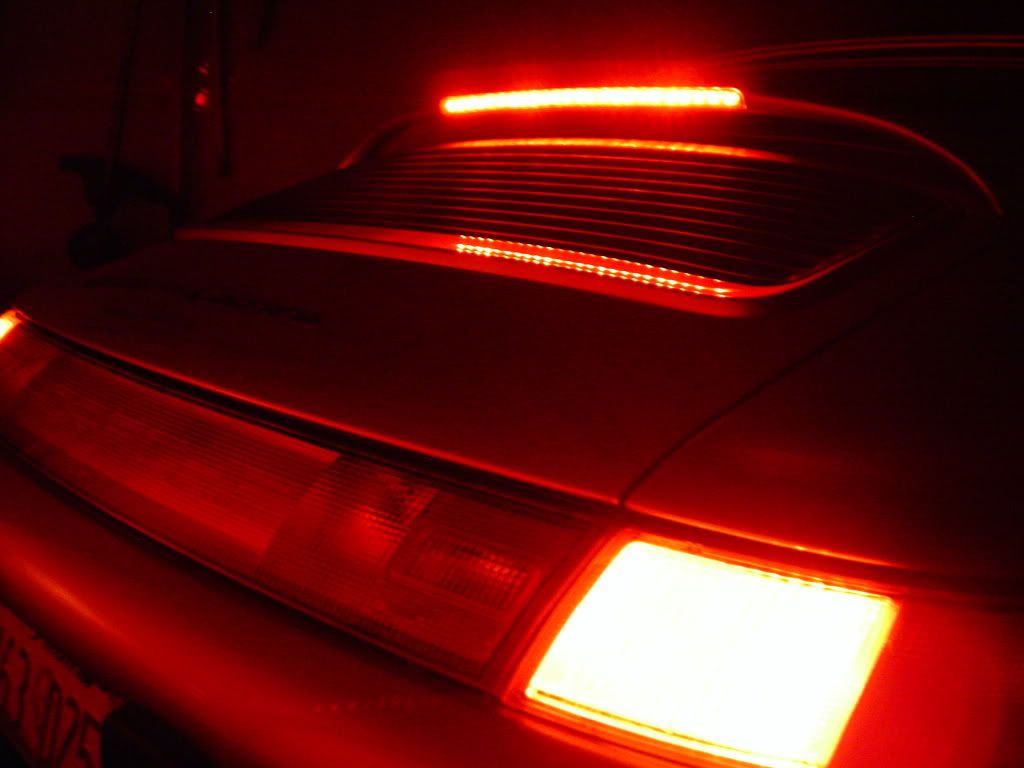
As soon as I opened the garage door camera fogged up sorry.
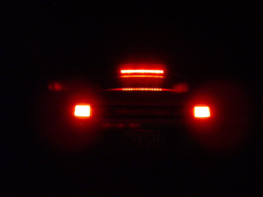
I am very happy with the results and it was an easy mod for less than $30.
The specs on the bulbs I used versus the ones you are thinking of using:
Diameter mine 5.6mm ,original were 5.5mm these fit just right, 3.2mm will probably need tube around them to center in the hole in the housing.
Viewing angle: mine 100 degrees, digikey are 45 degrees. 100 dg. bounces light nicely off the reflector and makes it look full not focused points of light.
Luminous intensity (no idea what this measures): mine are listed as 5600mcd, digikey are listed as 170mcd. I really hope there is a difference in the test procedure because I wouldn't want to go much dimmer than what I used. They are brighter than the incandescents but not blingy bright.
I am not trying to discourage you from using the bulbs you listed but I had tried a couple of 2.0 volt LEDs from the Shack and they looked like tiny nipples in the reflector, no specs listed on package.
That's just my 2 cents after seeing mine on the car. Keep us posted on the progress.
Cheers and Happy New Year!
First a couple of pictures, engine off just battery voltage: (no it is not photoshopped, garage door closed and light reflecting off white door, pretty cool effect though)
As soon as I opened the garage door camera fogged up sorry.
I am very happy with the results and it was an easy mod for less than $30.
The specs on the bulbs I used versus the ones you are thinking of using:
Diameter mine 5.6mm ,original were 5.5mm these fit just right, 3.2mm will probably need tube around them to center in the hole in the housing.
Viewing angle: mine 100 degrees, digikey are 45 degrees. 100 dg. bounces light nicely off the reflector and makes it look full not focused points of light.
Luminous intensity (no idea what this measures): mine are listed as 5600mcd, digikey are listed as 170mcd. I really hope there is a difference in the test procedure because I wouldn't want to go much dimmer than what I used. They are brighter than the incandescents but not blingy bright.
I am not trying to discourage you from using the bulbs you listed but I had tried a couple of 2.0 volt LEDs from the Shack and they looked like tiny nipples in the reflector, no specs listed on package.
That's just my 2 cents after seeing mine on the car. Keep us posted on the progress.
Cheers and Happy New Year!
12-31-2009, 09:53 PM
#74
Burning Brakes
01-01-2010, 04:38 AM
#75
Pro
Join Date: Aug 2006
Location: Schaumburg, IL.
Posts: 548
Likes: 0
Received 0 Likes
on
0 Posts
OK my idea is workable. It's really quite simple as well. Convert the entire light bar to be a low voltage (1.7V - 3.2V depending on the LED's of choice) light bar. There are MANY LED options. I did a cost work up on buying some stuff bulk with parts I will probably use. I would have enough parts to do seven light bars. 7 kits consisting of...
1 piece of heat shrink tubing
1 22-27 Ohm (depending on final LED selection) 5 Watt (7.5mm diameter) current limiting resistor
28 (24 + 4 spare) 5mm Hi Intensity LEDS.
The cost for enough parts to do 7 light bar kits to my house (including shipping) is $25.63
That is $3.66 per kit shipped to me.
1. Install is simple. See this thread's post #1 PDF files for light bar removal and instructions on getting the light bar apart.
2. Heat up your soldering iron and remove the bulbs from the light bar's circuit board replacing them with LED's as you go so you can get them at the right height. make sure the long leg of the LED's go to the circuit board contact that is fed by the black wire (B+). Trim excess leg length off the LED's after soldering them in. Sell your harvested bulbs to someone and get all your money back for this LED mod
3. Since you have your soldering iron heated up anyway, now comes the last part. Cut the black wire feeding the light bar it's B+ and solder the resistor into the cut wire. The resistor should be positioned outside the light bar assembly when re-assembled but close to the light bar. NOTE: It may also be possible to put the resistor inside the light bar. I won't know for sure until I actually perform this mod.
4. Plug light bar back into black and brown wires in the car. Test. If nothing works you can reverse the black and brown wires to the light bar as long as you soldered all the LED's in the same way. If some LED's don't work verify they are soldered in correctly and have good solder joints. If they still don't work there are 4 spares. Change out the ones that don't work.
5. When they all work re-assemble the light bar. Put the heat shrink tubing over the "wire-resistor-wire" junction and shrink it using the soldering iron or other heat source. Re-install light bar and enjoy.
NOTE: When I say "light bar" I mean the encapsulated lighting assembly consisting of the red diffuser and everything within and NOT the basket handle.
Here's the tech specs for anyone interested.
I worked this up with high intensity led's with a forward voltage of 3.2V and a nominal current capacity of 20ma each. This will render the following tech specs.

I'm going to order some parts for my own. I will post pics when finished.
I will probably buy enough for the seven kits and after I post pics if anyone wants a kit I would imagine I could ship to anywhere in the US for about $5 total.
Nick
1 piece of heat shrink tubing
1 22-27 Ohm (depending on final LED selection) 5 Watt (7.5mm diameter) current limiting resistor
28 (24 + 4 spare) 5mm Hi Intensity LEDS.
The cost for enough parts to do 7 light bar kits to my house (including shipping) is $25.63
That is $3.66 per kit shipped to me.
1. Install is simple. See this thread's post #1 PDF files for light bar removal and instructions on getting the light bar apart.
2. Heat up your soldering iron and remove the bulbs from the light bar's circuit board replacing them with LED's as you go so you can get them at the right height. make sure the long leg of the LED's go to the circuit board contact that is fed by the black wire (B+). Trim excess leg length off the LED's after soldering them in. Sell your harvested bulbs to someone and get all your money back for this LED mod
3. Since you have your soldering iron heated up anyway, now comes the last part. Cut the black wire feeding the light bar it's B+ and solder the resistor into the cut wire. The resistor should be positioned outside the light bar assembly when re-assembled but close to the light bar. NOTE: It may also be possible to put the resistor inside the light bar. I won't know for sure until I actually perform this mod.
4. Plug light bar back into black and brown wires in the car. Test. If nothing works you can reverse the black and brown wires to the light bar as long as you soldered all the LED's in the same way. If some LED's don't work verify they are soldered in correctly and have good solder joints. If they still don't work there are 4 spares. Change out the ones that don't work.
5. When they all work re-assemble the light bar. Put the heat shrink tubing over the "wire-resistor-wire" junction and shrink it using the soldering iron or other heat source. Re-install light bar and enjoy.
NOTE: When I say "light bar" I mean the encapsulated lighting assembly consisting of the red diffuser and everything within and NOT the basket handle.
Here's the tech specs for anyone interested.
I worked this up with high intensity led's with a forward voltage of 3.2V and a nominal current capacity of 20ma each. This will render the following tech specs.
I'm going to order some parts for my own. I will post pics when finished.
I will probably buy enough for the seven kits and after I post pics if anyone wants a kit I would imagine I could ship to anywhere in the US for about $5 total.
Nick
Last edited by Warpig; 01-01-2010 at 04:53 AM.