When you click on links to various merchants on this site and make a purchase, this can result in this site earning a commission. Affiliate programs and affiliations include, but are not limited to, the eBay Partner Network.
Typical DIY mistake... I was going to pull the clock out to clean the glass etc and saw there was a wire that was previously pulled out of the harness (looks like a green/yellow, and comes out together with a white wire)
i then proceed to pull out the harness to try and see where it should go and now rather than have 1 loose wire, I have 13....
does anyone have a link to a wiring diagram or list about which wire should go where? I�ve seen a few 964 ones online but I seen to have a few wires that the 964 one doesn�t, I have a white wire and 2 green/yellows (one that is the loose one)
thanks for all forum passionatics I�ve managed to stuff 10 wires correctly back into the plug
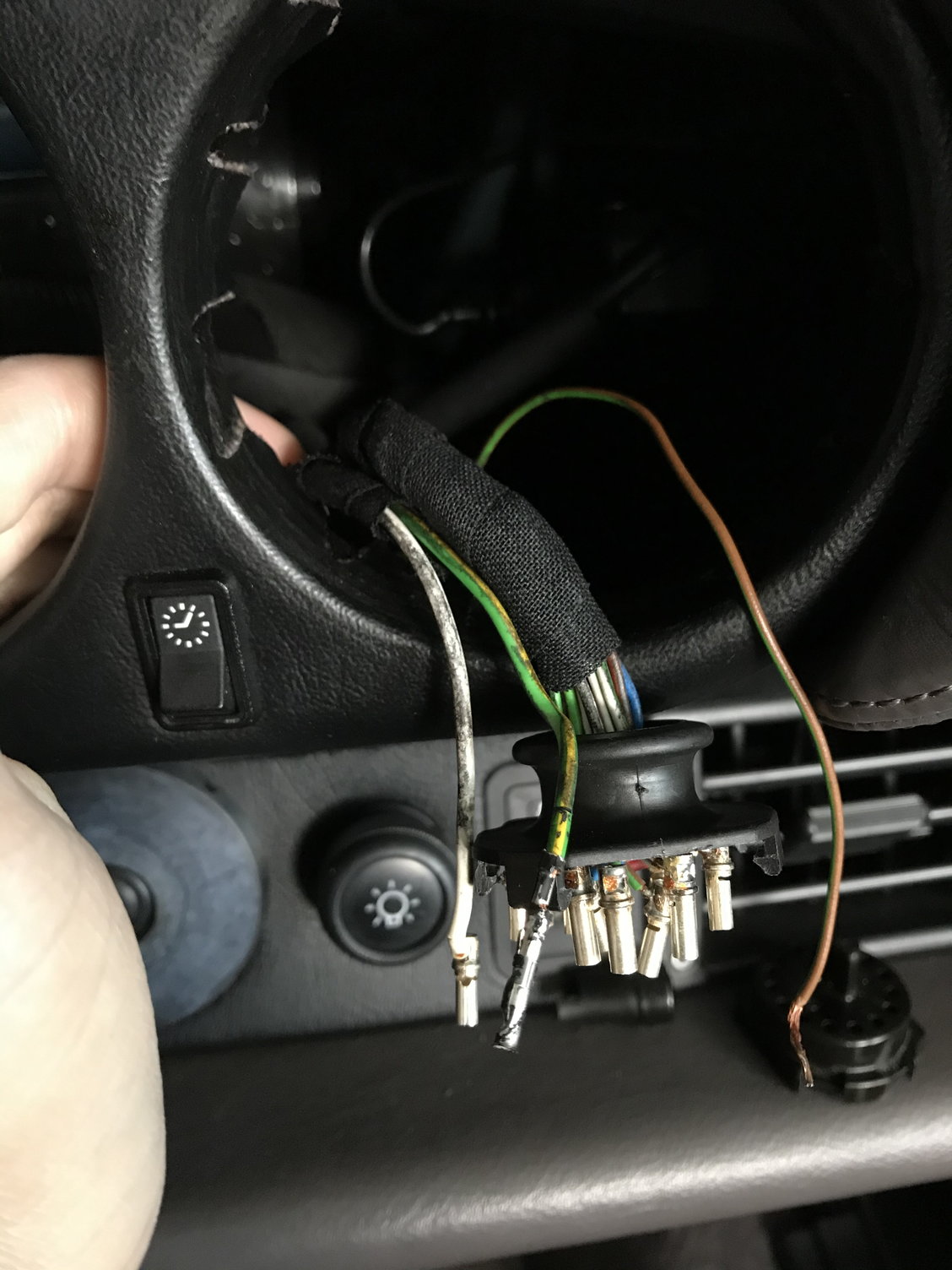
However, i now am left with 2 separate wires which I�m not sure where they are supposed to go. They exist the main harness from a separate exit to the clock harness as the picture shows. 1 is plain white and one is green/yellow. I�ve traced both wires back to the main harness and they don�t look like a hack job that someone has done.
i don�t seem any plain white wires in the big 993 instrument wiring diagram
Would really appreciate any enlightenment what these wires are and where they go.
Do you have a Green/Yellow in the clock plug too? green/Yellow is tied into Spoiler in that location (clock). Not seeing a White only wire in the schematics associated with the clock.
i see a Brown/Green wire in the photo too, but you do’nt mention it. Green Brown in that area is V-Belt related.
the green brown is the clock adjustment, goes into the clock next to the main plug
am just left with the white and green/yellow wire now
im suspecting they may be an aftermarket modification by a previous owner as nowhere in the schematics is there a solid white wire. If so a pretty good job as he�s slipped both wires into the main bundle of harness wires

 01-09-2020, 08:27 PM