When you click on links to various merchants on this site and make a purchase, this can result in this site earning a commission. Affiliate programs and affiliations include, but are not limited to, the eBay Partner Network.
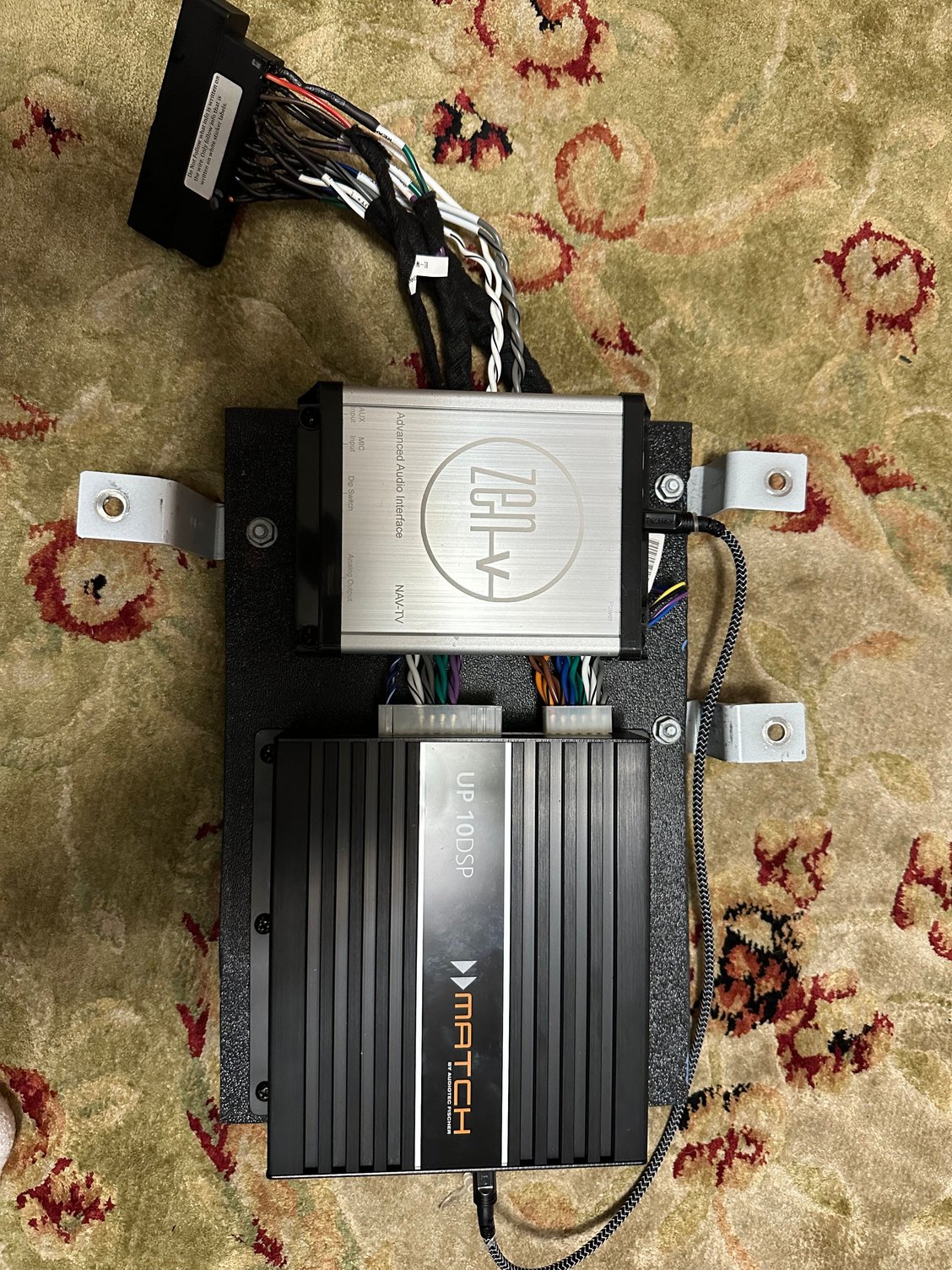
I have started to assemble my costly journey to adding this to my 981S with bose. I have sourced a Radio, Connectors/Harnesses, Nav-TV Zen V and will be getting a Match Up 10DSP., I have a PIWIS 3 clone and MIB2 Tool box as software to use. I will post my progress on this journey. I wil outline my thoughts and chanllenges. Hopefully this will help others and me on this mod.
Software
1.My understanding I need to upgrade the software on the cluster. Will need to figure out how and what software patch I need. I think this is where PIWiS comes in.
2.MIB Toolbox will allow me to program radio wo work. I think you can tell it which updates to perform. I am hoping to leave Bose function (amp function) intact. I want to use harnesses with no modifying of factory wires. I will be running new tweeter wires to have everything on separate channels.
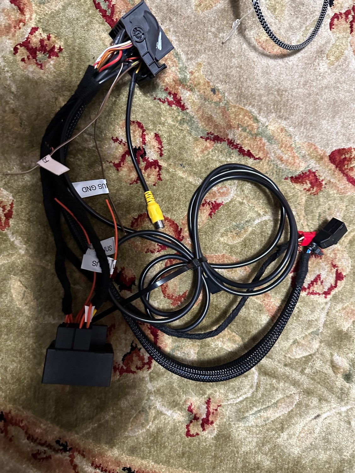
I received my harnesses today. I have started putting them together and I have run into my first snag. Pins that I am not sure I need or where they go on corresponding end. I will list below and if anyone can help I would greatly appreciate it.
On PCM 3.1 I have the following pins that I am not sure I need or where they connect on the PCM 4.0 Some of these have similar names on pcm 4 but I want to make sure
Connector A
Pin 14 ANT
Pin 16 Wake
Connector C
Pin 3 Mic Shield
Pin 4 Amp On
Pin 12 BT H/S
Connector D
Pin 1 Ipod Det
Pin 3 Ipod Chg-
Pin 8 Aux RTN
Pin 11 Ipod ACC ID
Pin 12 Ipod CHG +
Update on PCM 4.0 harness. Since I will be trying most150. The connections were less
I have the pigtail that was on radio and only the following are being used
pin15
pin16
connector e
pin 1-3,6-8,12
connector b
pin1,2,6-8 and 12
connector c
pin1-3 and 7,8
so I have the following two questions
1. pin 3 on connector E is ring break diagnostics. What is that for and do I need it?
2. usb connects to a hub that I guess does glovebox and center console usbs. The question is do I need it? If I get it does it need to be programmed? I noticed that the harness on the pcm has usb and six so is that the glovebox and I don�t need the hub?
Completed my pin tracking. except for one that I think I do not need pin 3 on connector E is ring break diagnostics. I think it's for the Bose Amp which I will not be using.
Started Ordering hte USB ub parts. I am trying to use OEM when Possible. So ordered arm rest usb and usb Hub. Just have to get the cables from hub to usb connectors and pigtail to usb. trying to find used to keep cost down.
Process is slow but starting to feel I am getting this. On the hardware side still need to look for aftermarket amp, harness to replace Bose connection. Still concerned with being able to use clone PIWIS 3 to program. I will cross that bridge once all the hardware is assembled.
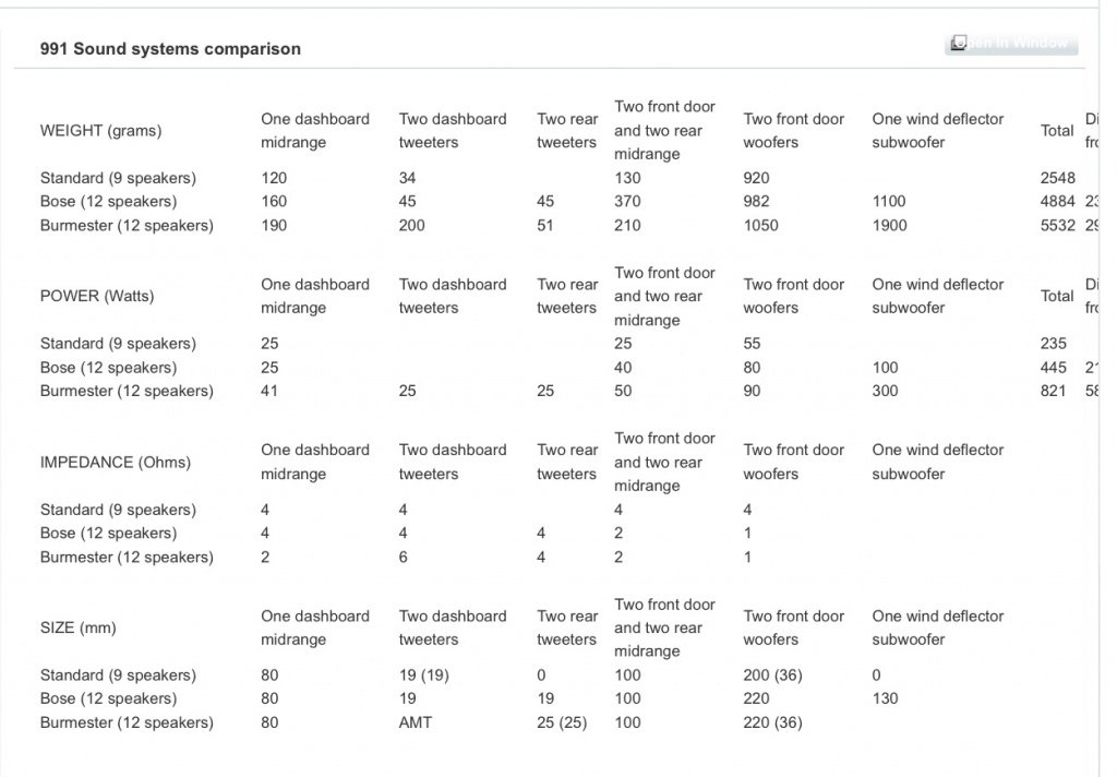
I have been emailing Audiotec Fischer who is saying that I need to change the mids and and the Door woofers are not compatible with the Match up 10DSP they are saying the mids are 2ohm and the woofers are 1 ohm. I see that Musicar NW is using it with stock Bose speakers. Can anyone confirm. They said the tweeters and the center channel are 4ohm but the rest are not.
I can confirm, If you have Bose or Burmeister the midrange and woofers are not 4ohm.
Im not certain, but I think the door woofers are 2-ohms and are wired in parallel, that is why they are listed as 1 ohm in this chart.
Honestly, I wouldn�t bother hooking up the rear or center channels. A Helix V8 instead of the Match amp would work better here and supports 2-ohm loads.
if you want a plug and play solution try contacting Musicar. Thier stage 2 solution replaces the amplifier, and works with Bose speakers.
Last edited by DriverDaily; 12-03-2022 at 12:20 PM.
I can confirm, If you have Bose or Burmeister the midrange and woofers are not 4ohm.
Im not certain, but I think the door woofers are 2-ohms and are wired in parallel, that is why they are listed as 1 ohm in this chart.
Honestly, I wouldn�t bother hooking up the rear or center channels. A Helix V8 instead of the Match amp would work better here and supports 2-ohm loads.
if you want a plug and play solution try contacting Musicar. Thier stage 2 solution replaces the amplifier, and works with Bose speakers.
Just got the amp since musicar told me the speakers where 4ohm. They use the match up 10dsp on their setup. I will have to replace the 4� speakers. Any suggestions that are not too expensive on par for now with Bose in there. Do you know what to do to separate the woofers?
Just got the amp since musicar told me the speakers where 4ohm. They use the match up 10dsp on their setup. I will have to replace the 4” speakers. Any suggestions that are not too expensive on par for now with Bose in there. Do you know what to do to separate the woofers?
First, if you're concerned about cost, buy the "Sound Package Plus" factory midrange. The Bose speakers are nothing special.
Rennspec Audio used to sell adapters for cheaper speakers, but I guess it wasn't profitable because they shut down.
If you want a better sounding solution I created a free bracket for the Audio Development MM4 here. You can get my bracket SLS 3D printed from a service like Shapeways. That's a $500 midrange though.
Second, no rewiring should be needed at the amp side, the Bose amp has separate left and right inputs for the door woofers. If they're actually in parallel then it's done inside the amp. Here is the wiring diagram for Bose.
Speaking of wiring, you can buy a harness that will plug into your OEM amplifier harness so you don;t need to splice anything. Read this post from my build log here.
Third, do you have a copy of the workshop manual? All the system wiring diagrams are at the very end. finding those diagrams answered a ton of unknowns in my build.
Last edited by DriverDaily; 12-03-2022 at 04:50 PM.
Update amp and most150 done. I am wiring amp directly not to Oem harness. Also have to run wiring to separate tweeters. I need to get 4 4� mi range speakers since the Bose are 2 ohm not 4 as I was lead to believe. May have to wait till weather gets better to continue since I have to do more than I originally thought.
First, if you're concerned about cost, buy the "Sound Package Plus" factory midrange. The Bose speakers are nothing special.
Rennspec Audio used to sell adapters for cheaper speakers, but I guess it wasn't profitable because they shut down.
If you want a better sounding solution I created a free bracket for the Audio Development MM4 here. You can get my bracket SLS 3D printed from a service like Shapeways. That's a $500 midrange though.
Second, no rewiring should be needed at the amp side, the Bose amp has separate left and right inputs for the door woofers. If they're actually in parallel then it's done inside the amp. Here is the wiring diagram for Bose.
Speaking of wiring, you can buy a harness that will plug into your OEM amplifier harness so you don;t need to splice anything. Read this post from my build log here.
Third, do you have a copy of the workshop manual? All the system wiring diagrams are at the very end. finding those diagrams answered a ton of unknowns in my build.
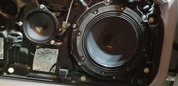
I ordered some audison 4ap primas. Can I use the adapter you created or do I need to have it modded?
I ordered some audison 4ap primas. Can I use the adapter you created or do I need to have it modded?
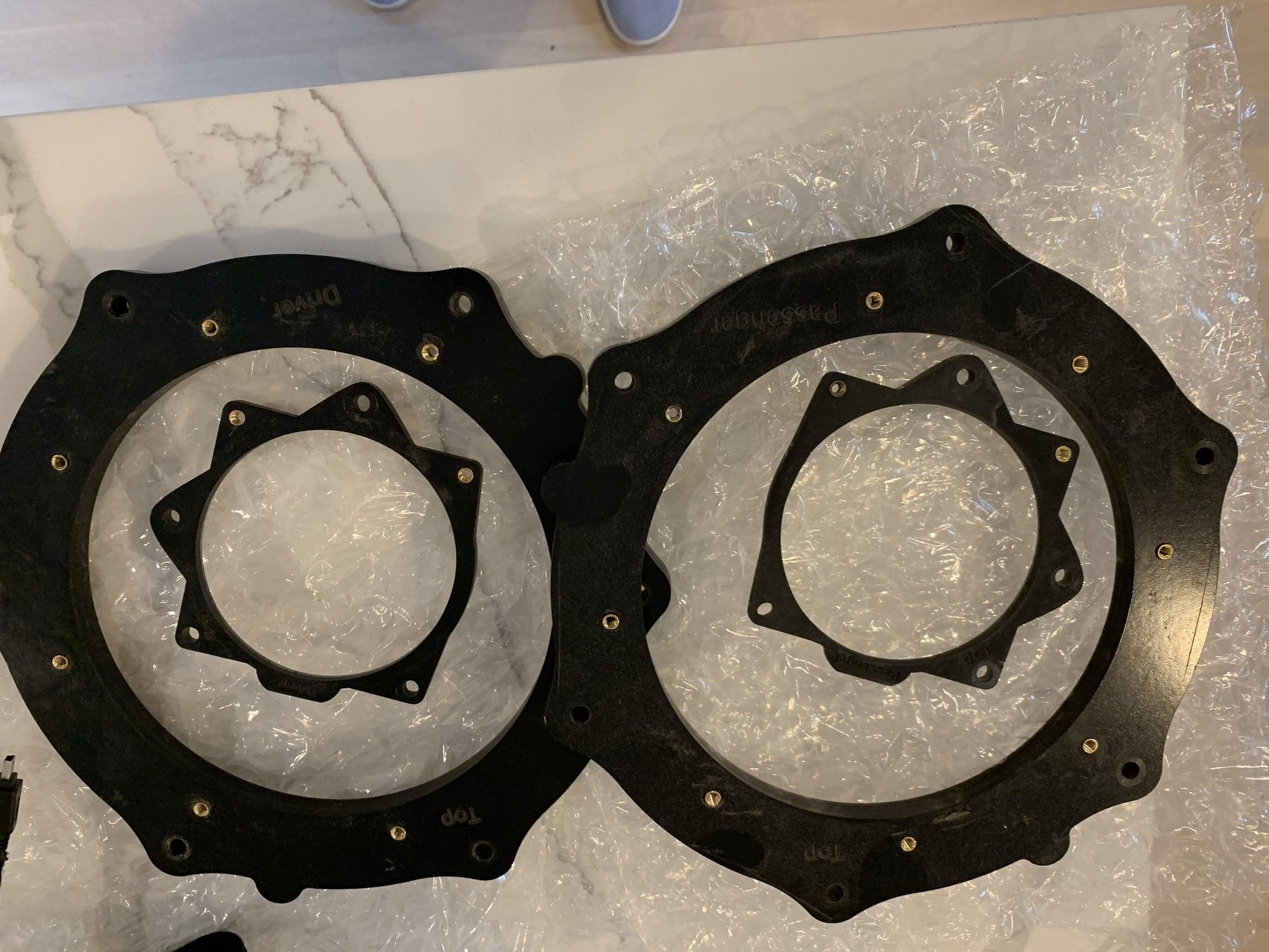
My adapter definately won't fit the Audisons. Mounting holes aren't even close.
The adapter that @Rennspec.com created is a really elegant solution that hides a ton of complexity.
3 OEM screws mount from the front.
2/3 OEM screws help hold the audison in place.
2 extra screws mount from behind to hold the Audison. These need threads pressed or modeled in and screws sized to avoid interference on the back.
There may be a specific orientation needed to avoid interference with the plastic mount bit in the top left, or piece that juts out inside the cavity for that matter.
1 of the 3 OEM holes is actually farther from the center of the cavity than the other 2. This is why my adapter has U shaped mounting instead of regular holes.
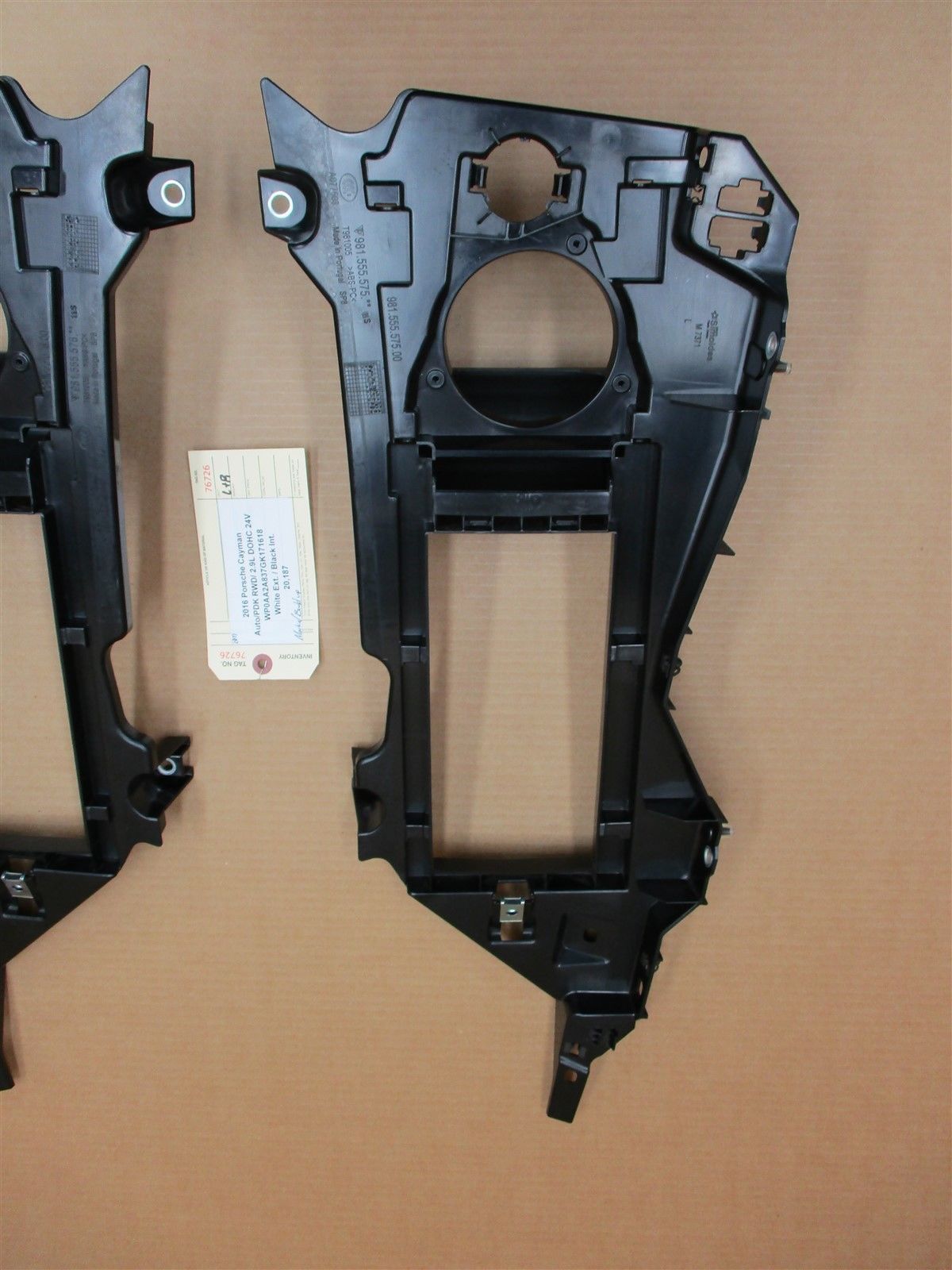
Finally, there's no way that same adaptor is fitting in the rear bracket. The mount is molded for the OEM speaker.
Last edited by DriverDaily; 12-05-2022 at 09:21 PM.
My adapter definately won't fit the Audisons. Mounting holes aren't even close.
The adapter that @Rennspec.com created is a really elegant solution that hides a ton of complexity.
3 OEM screws mount from the front.
2/3 OEM screws help hold the audison in place.
2 extra screws mount from behind to hold the Audison. These need threads pressed or modeled in and screws sized to avoid interference on the back.
There may be a specific orientation needed to avoid interference with the plastic mount bit in the top left, or piece that juts out inside the cavity for that matter.
1 of the 3 OEM holes is actually farther from the center of the cavity than the other 2. This is why my adapter has U shaped mounting instead of regular holes.
Finally, there's no way that same adaptor is fitting in the rear bracket. The mount is molded for the OEM speaker.
Thanks for the pics. This is helpful. I wonder if the rears can be mounted from underneath. I guess I will find out once the parts arrive and the weather is better.
Thanks for the pics. This is helpful. I wonder if the rears can be mounted from underneath. I guess I will find out once the parts arrive and the weather is better.
Originally Posted by DriverDaily
Rear speakers are just going to make your system more expensive, sound worse, and harder to tune. Especially in a car without a back seat�
I got a file for the dsp from a audio tuner so hopefully it will be ok. I agree more expensive. But I ordered the speakers and since the car had some I figured why not. As long as it sounds the same or better than currently I will be happy.
I got a file for the dsp from a audio tuner so hopefully it will be ok. I agree more expensive. But I ordered the speakers and since the car had some I figured why not. As long as it sounds the same or better than currently I will be happy.
Somebody has a Helix DSP file specifically for Audison mids with OEM tweeters, midbass, and subs?

 11-08-2022, 09:59 AM