Lower balance shaft cover R&R
 04-07-2008, 09:16 AM
#1
Racer
Thread Starter
I hate oil leaks - hate ‘em! I consider them a sign that the vehicle owner lacks either pride or the wherewithal to fix them. This is my first time with a Porsche, but I’ve been into old Jeep Wagoneers and J-trucks for quite a while – I’m member #34 on the ww.ifsja.org list, which now has something like 15,000 members. When we would gather in places like Ouray, Colorado, you could tell the Full-Size Jeepers had been in town by the puddles in the hotel parking lots.
As noted, this is my first time working on a 968 engine, or any Porsche engine for that matter beyond occasionally changing the oil in my mother’s 944 in the mid-1980’s. I posted on the 968Forums that I needed help with R&R of the lower balance shaft (“LBS”) cover, but I got no replies and basically went into this flying blind except for what limited information is available at Clark’s Garage: http://www.clarks-garage.com/shop-manual/eng-14.htm
So I decided to track my progress, take photos along the way, and write about it for anyone else who finds themselves wanting or needing to do this job.
Okay, so you clicked on here for a write-up and not my editorializing? Here goes:
Thanks, also, to Raj for being on-the-spot for advice via cell phone; he guided me in advance to purchase Loctite 574, and I also knew the passenger-side motor mount would be in the way.
Access to the LBS cover assumes:
• timing belts & covers are removed;
• power steering pump loosened and hanging.
For additional clearance, I removed the following items:
• cooling fans;
• radiator;
• oil filter;
• oil pressure sending unit;
• small aluminum heat shield between exhaust and control arm.
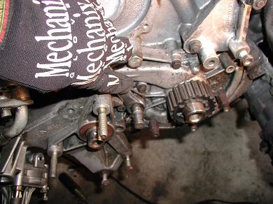
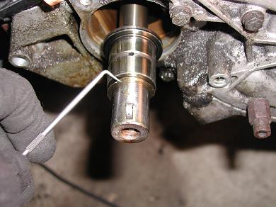
The first task is to remove the balance shaft front cover, as part of the larger task of replacing the front seals. With a pair of pliers, I gently pried out the woodruff key from the balance shaft snout. The front cover is held in place by:
• a pair of M8 (13mm) bolts above and below the seal;
• a 19mm wrench to remove the tensioning arm lever spindle;
• a 6mm hex-head bolt next to the tensiong arm lever spingle;
• an M8 bolt behind the housing.
After removing these fasteners, the front cover comes off fairly easily. I pried gently with a screwdriver in combination with a gentle rap of a rubber hammer. This was also a good time to remove the mylar (thin, clear plastic) seal from the LBS snout.
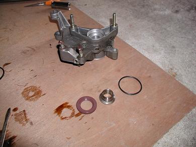
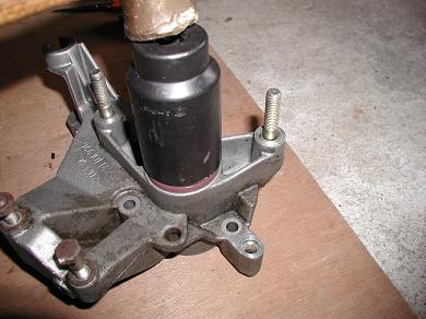
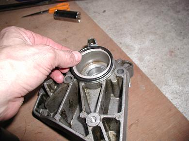
To remove the front seal and race, I suspended the front cover assembly on a drift (a large screwdriver would work, as well), making sure only the metal race is sitting atop the drift. A couple of raps with the rubber hammer and – voila! – both the race and seal pop out together.
Take caution not to score or gouge the inner surfaces of the aluminum cover, which would essentially create a trough for oil to seep around your new seal. (I learned this the hard way, after replacing the output shaft seal on a NP-208 transfer case a few years ago.)
After cleaning the front cover, I a combined a new race and 30x48x7 seal, helped by a slight amount of oil. Inspect the back of the seal to ensure the lip is not folded and that the spring is in place.
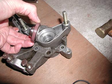
Set the seal into the front housing cover using a brass hammer and a 36mm impact socket. Rap gently and evenly; the intention is to make the perimeter of the seal flush with (or very slightly beneath) the edges of the cover opening. But, as importantly, make the best effort to set the seal perfectly even all the way around, so that the seal’s inner surface rides perpendicular to the balance shaft and thus has its best chances of containing oil inside a rotating shaft.
You should be able to turn the race inside the seal but feel that it is snugly fit. The race will have some for-and-aft play between the seal and housing.
Also install a new black O-ring rubber seal at the back of the front housing cover. This assembly can now be set aside.
Upon inspecting the old seal and race, I could tell that the seal fit very loosely and was probably 90% of my oil leak problem. But I had also noted oil seepage at the rear of the lower balance shaft cover and couldn’t discern if that was from oil flowing backwards along the oil pan gasket or if it was another leak entirely. So, since I’d come this far, better to err on the side of caution and tackle resealing the LBS cover.
Raj suggested strongly that I remove the passenger-side motor mount to create access to the LBS cover. This would entail carefully suspending the engine, via a jack (and padding with a piece of wood) underneath the oil pan, then removing the bracket that mounts the engine block to the frame mount.
But, in my case, I saw that the bolts holding that bracket to the engine block were themselves difficult to access without also removing the exhaust manifold(s), so I opted to do the best I could with that bracket still in place.
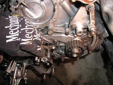
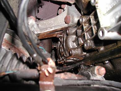
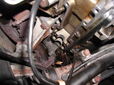
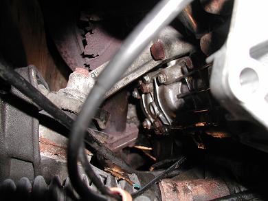
The M8 bolts came out of the LBS cover very easily, as did about half of the M6 bolts. The others were badly corroded such that my arsenal of 10mm wrenches was rendered futile; so I used a pair of ordinary vise-grips and carefully turned them out.
As shown in the photo, two of the M6 bolts will not come out of the LBS cover because of the exhaust manifold and engine mount bracket, so I left them in place temporarily. These are bolts #15 and #5, respectively, in the Clark’s Garage diagram: http://www.clarks-garage.com/graphics/bshaft2.gif
Standing over the front of the engine, I popped the LBS cover loose by gently prying on the front snout of the LBS. I’m blessed with long simian arms, so this wasn’t difficult for me, but others may find this easier to do while lying beneath the front end of the car.
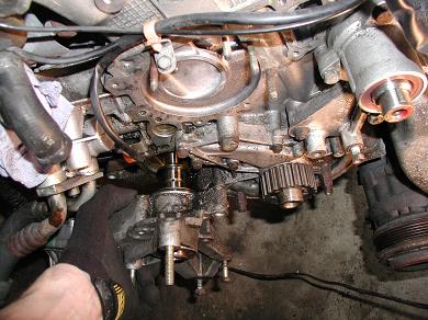
It all came out together very nicely. The only part that fell on the floor was the rear seal cap.
I want to note also how surprised I was to find not a trace of sealant between the mating surfaces of the LBS cover and the engine housing. Perhaps some form of sealant was used that I could not see 16 years later; however, this is evidence once again of how carefully this engine was fit together during manufacture!
I cleaned the parts and laid them out for photos.
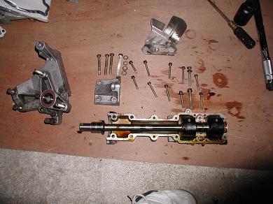
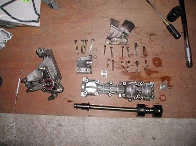
Installation, in this case, is not necessarily the same as removal.
First, I ran a thin bead of Loctite 574 around the edges of the LBS cover, also on the mating surfaces adjacent to the bearing cap (making sure to leave the channels around them clean). I forewent the advised “velour roller” and smeared the Loctite evenly with my finger (‘cuz that’s how a man does it!)
Loctite’s website has a spec sheet on 574, which notes the curing times according to ambient temperature: http://65.213.72.112/tds5/docs/574-EN.pdf
It was around 40F in the garage last night, so I felt no sense of hurry for sake of the sealant curing too quickly.
I installed a new rubber o-ring on the rear LBS plug, and set that plug in its place in the LBS cover. I lubricated the bearing surface with a dab of engine oil. And I set the balance shaft into the cover, creating a loose assembly with which I would have to be careful while reinstalling.
And here’s where I cheated a bit and, again, went against Raj’s advice that I should use bolts of the same length: Those two pesky M6 bolts that gave me fits earlier, #15 and #5, I replaced with M6x45’s, a few milimeters shorter than the originals, and set them into their respective holes in the LBS cover before putting it all up agains the engine block. This absolutely made the job possible without having to remove the motor mount and/or exhaust manifold.
Again, blessed with simian features including large gnarly hands, I could managed this without too much ado. Others might want to dab a bit of vaseline or grease into those holes in order to hold the bolts in place. (Don’t get too Freudian in your interpretation of what I’ve written here. It’s car repair, after all!)
I held the cover and balance shaft in place while threading finger-tight one of the M8 bolts (shown as #2/18 on the Clark’s Garage diagram). I also threaded to finger-tightness the four M8 bolts at the front (shown as #11-14); these bolts also secure the power steering pump bracket onto the LBS cover.
I couldn’t exactly follow the tightening sequence shown in that diagram, because the #5 and #3 bolts would be difficult to access with the #1/17 bolt in the way, moresoe with the exhaust manifold and motor mount bracket making life difficult. (A note about tightening sequences in general, for those who don’t already know, is that a specified sequence is generally intended to begin tightening at a “Bolt 1” and to approximate a spiralling pattern of fasteners away from “Bolt 1.”)
I installed all of the M6 bolts to finger-tight. Next, using a short 10mm wrench, I snugged bolt #5. (By “snug” I mean that which can be accomplished with a short wrench without excessive effort. No way could I fit a torque wrench in there to ensure 7 ft-lbs, so this is how I did it. Before every bolt, I practice feeling the proper torque by turning a torque wrench on a bolt remote from my work)
Similarly, I hand-snugged the #1/17 bolt to approximately 11 ft-lbs.
Then I tightened to snug all of the M6 bolts, with the tightening sequence made necessary by the room I had to work in: 6–3–4–7–8–9–10
Bolts #11–14 were fairly easy to access, so they were properly torqued to 14 ft-lbs.
Bolt #15 had to be hand-snugged, again, after a practice run with a torque wrench on another bolt. Admittedly, this could prove to be the Achilles’ Heel of the whole job, as that bolt is shorter than the others and thus has less thread; also because it is placed at the corner of the LBS cover and therefore a crucial place for proper fitment. Time will tell.
Bolt #16 could be accessed with a torque wrench.
Finally, I torqued bolt #2/18 to 24 ft-lbs without much trouble; however, I had to use a swivel extension for #1/17 due to the mounting bracket being in the way.
I looked about the outer edges of the LBS to ensure an even bead of the Loctite 574 was slightly oozed around the edges. The orange color was ideal for this.
I reinstalled the heat shield and oil pressure sending unit.
Prior to installing the front housing, I placed a new mylar seal onto the snout of the balance shaft.
Making sure to dab a bit of oil around the black rubber O-ringI fit the housing in place. I used the two M8 bolts to tighten and seat the housing in place.
Replace the 6mm hex-head bolt.
With a 19mm wrench reinstall the tensioning lever spindle.
Don’t forget the M8 bolt at the back of the housing.
Replace the Woodruff key.
I had other work to do on the car; namely, replace the cam chain & tensioner, other front seals, valve cover gasket(s), water pump, timing & balance belts, and drive belts, and then fill the engine with oil. Because of this other work, I was certain to give the Loctite 574 time to cure.
It was a success! Upon start-up, the LBS rattled for 1-2 seconds and then quieted as soon as it received fresh engine oil on its bearing surfaces. I'll occasionally check those two short bolts on the LBS cover, just to make sure they don't slip out on me.
As noted, this is my first time working on a 968 engine, or any Porsche engine for that matter beyond occasionally changing the oil in my mother’s 944 in the mid-1980’s. I posted on the 968Forums that I needed help with R&R of the lower balance shaft (“LBS”) cover, but I got no replies and basically went into this flying blind except for what limited information is available at Clark’s Garage: http://www.clarks-garage.com/shop-manual/eng-14.htm
So I decided to track my progress, take photos along the way, and write about it for anyone else who finds themselves wanting or needing to do this job.
Okay, so you clicked on here for a write-up and not my editorializing? Here goes:
Thanks, also, to Raj for being on-the-spot for advice via cell phone; he guided me in advance to purchase Loctite 574, and I also knew the passenger-side motor mount would be in the way.
Access to the LBS cover assumes:
• timing belts & covers are removed;
• power steering pump loosened and hanging.
For additional clearance, I removed the following items:
• cooling fans;
• radiator;
• oil filter;
• oil pressure sending unit;
• small aluminum heat shield between exhaust and control arm.
The first task is to remove the balance shaft front cover, as part of the larger task of replacing the front seals. With a pair of pliers, I gently pried out the woodruff key from the balance shaft snout. The front cover is held in place by:
• a pair of M8 (13mm) bolts above and below the seal;
• a 19mm wrench to remove the tensioning arm lever spindle;
• a 6mm hex-head bolt next to the tensiong arm lever spingle;
• an M8 bolt behind the housing.
After removing these fasteners, the front cover comes off fairly easily. I pried gently with a screwdriver in combination with a gentle rap of a rubber hammer. This was also a good time to remove the mylar (thin, clear plastic) seal from the LBS snout.
To remove the front seal and race, I suspended the front cover assembly on a drift (a large screwdriver would work, as well), making sure only the metal race is sitting atop the drift. A couple of raps with the rubber hammer and – voila! – both the race and seal pop out together.
Take caution not to score or gouge the inner surfaces of the aluminum cover, which would essentially create a trough for oil to seep around your new seal. (I learned this the hard way, after replacing the output shaft seal on a NP-208 transfer case a few years ago.)
After cleaning the front cover, I a combined a new race and 30x48x7 seal, helped by a slight amount of oil. Inspect the back of the seal to ensure the lip is not folded and that the spring is in place.
Set the seal into the front housing cover using a brass hammer and a 36mm impact socket. Rap gently and evenly; the intention is to make the perimeter of the seal flush with (or very slightly beneath) the edges of the cover opening. But, as importantly, make the best effort to set the seal perfectly even all the way around, so that the seal’s inner surface rides perpendicular to the balance shaft and thus has its best chances of containing oil inside a rotating shaft.
You should be able to turn the race inside the seal but feel that it is snugly fit. The race will have some for-and-aft play between the seal and housing.
Also install a new black O-ring rubber seal at the back of the front housing cover. This assembly can now be set aside.
Upon inspecting the old seal and race, I could tell that the seal fit very loosely and was probably 90% of my oil leak problem. But I had also noted oil seepage at the rear of the lower balance shaft cover and couldn’t discern if that was from oil flowing backwards along the oil pan gasket or if it was another leak entirely. So, since I’d come this far, better to err on the side of caution and tackle resealing the LBS cover.
Raj suggested strongly that I remove the passenger-side motor mount to create access to the LBS cover. This would entail carefully suspending the engine, via a jack (and padding with a piece of wood) underneath the oil pan, then removing the bracket that mounts the engine block to the frame mount.
But, in my case, I saw that the bolts holding that bracket to the engine block were themselves difficult to access without also removing the exhaust manifold(s), so I opted to do the best I could with that bracket still in place.
The M8 bolts came out of the LBS cover very easily, as did about half of the M6 bolts. The others were badly corroded such that my arsenal of 10mm wrenches was rendered futile; so I used a pair of ordinary vise-grips and carefully turned them out.
As shown in the photo, two of the M6 bolts will not come out of the LBS cover because of the exhaust manifold and engine mount bracket, so I left them in place temporarily. These are bolts #15 and #5, respectively, in the Clark’s Garage diagram: http://www.clarks-garage.com/graphics/bshaft2.gif
Standing over the front of the engine, I popped the LBS cover loose by gently prying on the front snout of the LBS. I’m blessed with long simian arms, so this wasn’t difficult for me, but others may find this easier to do while lying beneath the front end of the car.
It all came out together very nicely. The only part that fell on the floor was the rear seal cap.
I want to note also how surprised I was to find not a trace of sealant between the mating surfaces of the LBS cover and the engine housing. Perhaps some form of sealant was used that I could not see 16 years later; however, this is evidence once again of how carefully this engine was fit together during manufacture!
I cleaned the parts and laid them out for photos.
Installation, in this case, is not necessarily the same as removal.
First, I ran a thin bead of Loctite 574 around the edges of the LBS cover, also on the mating surfaces adjacent to the bearing cap (making sure to leave the channels around them clean). I forewent the advised “velour roller” and smeared the Loctite evenly with my finger (‘cuz that’s how a man does it!)
Loctite’s website has a spec sheet on 574, which notes the curing times according to ambient temperature: http://65.213.72.112/tds5/docs/574-EN.pdf
It was around 40F in the garage last night, so I felt no sense of hurry for sake of the sealant curing too quickly.
I installed a new rubber o-ring on the rear LBS plug, and set that plug in its place in the LBS cover. I lubricated the bearing surface with a dab of engine oil. And I set the balance shaft into the cover, creating a loose assembly with which I would have to be careful while reinstalling.
And here’s where I cheated a bit and, again, went against Raj’s advice that I should use bolts of the same length: Those two pesky M6 bolts that gave me fits earlier, #15 and #5, I replaced with M6x45’s, a few milimeters shorter than the originals, and set them into their respective holes in the LBS cover before putting it all up agains the engine block. This absolutely made the job possible without having to remove the motor mount and/or exhaust manifold.
Again, blessed with simian features including large gnarly hands, I could managed this without too much ado. Others might want to dab a bit of vaseline or grease into those holes in order to hold the bolts in place. (Don’t get too Freudian in your interpretation of what I’ve written here. It’s car repair, after all!)
I held the cover and balance shaft in place while threading finger-tight one of the M8 bolts (shown as #2/18 on the Clark’s Garage diagram). I also threaded to finger-tightness the four M8 bolts at the front (shown as #11-14); these bolts also secure the power steering pump bracket onto the LBS cover.
I couldn’t exactly follow the tightening sequence shown in that diagram, because the #5 and #3 bolts would be difficult to access with the #1/17 bolt in the way, moresoe with the exhaust manifold and motor mount bracket making life difficult. (A note about tightening sequences in general, for those who don’t already know, is that a specified sequence is generally intended to begin tightening at a “Bolt 1” and to approximate a spiralling pattern of fasteners away from “Bolt 1.”)
I installed all of the M6 bolts to finger-tight. Next, using a short 10mm wrench, I snugged bolt #5. (By “snug” I mean that which can be accomplished with a short wrench without excessive effort. No way could I fit a torque wrench in there to ensure 7 ft-lbs, so this is how I did it. Before every bolt, I practice feeling the proper torque by turning a torque wrench on a bolt remote from my work)
Similarly, I hand-snugged the #1/17 bolt to approximately 11 ft-lbs.
Then I tightened to snug all of the M6 bolts, with the tightening sequence made necessary by the room I had to work in: 6–3–4–7–8–9–10
Bolts #11–14 were fairly easy to access, so they were properly torqued to 14 ft-lbs.
Bolt #15 had to be hand-snugged, again, after a practice run with a torque wrench on another bolt. Admittedly, this could prove to be the Achilles’ Heel of the whole job, as that bolt is shorter than the others and thus has less thread; also because it is placed at the corner of the LBS cover and therefore a crucial place for proper fitment. Time will tell.
Bolt #16 could be accessed with a torque wrench.
Finally, I torqued bolt #2/18 to 24 ft-lbs without much trouble; however, I had to use a swivel extension for #1/17 due to the mounting bracket being in the way.
I looked about the outer edges of the LBS to ensure an even bead of the Loctite 574 was slightly oozed around the edges. The orange color was ideal for this.
I reinstalled the heat shield and oil pressure sending unit.
Prior to installing the front housing, I placed a new mylar seal onto the snout of the balance shaft.
Making sure to dab a bit of oil around the black rubber O-ringI fit the housing in place. I used the two M8 bolts to tighten and seat the housing in place.
Replace the 6mm hex-head bolt.
With a 19mm wrench reinstall the tensioning lever spindle.
Don’t forget the M8 bolt at the back of the housing.
Replace the Woodruff key.
I had other work to do on the car; namely, replace the cam chain & tensioner, other front seals, valve cover gasket(s), water pump, timing & balance belts, and drive belts, and then fill the engine with oil. Because of this other work, I was certain to give the Loctite 574 time to cure.
It was a success! Upon start-up, the LBS rattled for 1-2 seconds and then quieted as soon as it received fresh engine oil on its bearing surfaces. I'll occasionally check those two short bolts on the LBS cover, just to make sure they don't slip out on me.
Last edited by rdhayward; 04-15-2008 at 07:55 AM.
 04-08-2008, 09:48 AM
#3
Racer
Thread Starter
You're most welcome. The pics are all links to photos posted with an identical write-up at 968Forums. Sorry for the cross-reference if it offends anyone, but I wrote this to be informative to as many people as can use it.
04-09-2008, 03:59 PM
#4
Instructor
Join Date: Feb 2007
Location: Kentucky
Posts: 201
Likes: 0
Received 0 Likes
on
0 Posts
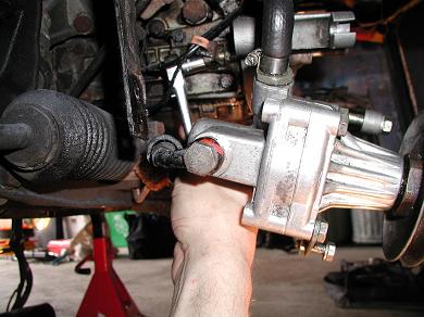
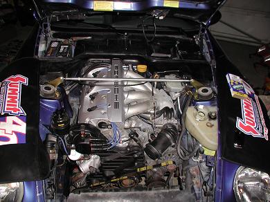
Good write-up! I just did my B/S seals as well, but not the housing cover reseal. Did you just have your power steering pump replaced? It looks so clean in your shot, but the crud on the sway bar bracket tells me you had a good sized leak there.
When I was trying to remove my P/S pump it was so dirty that I could not see the little iron spacer on the front bolt that comes out of the bracket. I could not figure out how to remove the pump,so I took it off with the bearing housing. After cleaning it off, it all became clear.
When I was trying to remove my P/S pump it was so dirty that I could not see the little iron spacer on the front bolt that comes out of the bracket. I could not figure out how to remove the pump,so I took it off with the bearing housing. After cleaning it off, it all became clear.
04-10-2008, 12:27 AM
#6
Racer
Thread Starter
Ryan, you are very observant, and, no, the PS pump isn't new. The entire engine was covered with grime. As well as I reasonably can, I take the time to clean as I go, in this case with a $3 parts cleaning brush and kerosene. Cleaning the nose/engine/tranny pans was the worst! BTW, I also replaced all the front swaybar & endlink bushings with new OEM rubber.
Trending Topics
 04-15-2008, 09:49 AM
#9
Rennlist Member
Ralph, thanks for sharing the pictures. Excellent details on the job.
Just don't ever snap those m8x58 bolts. They are around $10 each!!!
I told you its not that bad .
.
Raj
Just don't ever snap those m8x58 bolts. They are around $10 each!!!
I told you its not that bad
.Raj
04-16-2008, 09:18 AM
#11
Rennlist Member
Ralph, I will definitely be there but I plan to show up the morning of the event. I look forward to meeting you and others. I will most probably be coming with Steve in his amazing Speed Yellow Cabriolet.
Raj
Raj
11-15-2012, 04:18 PM
#12
8th Gear

Join Date: Jan 2012
Location: Sacramento
Posts: 8
Likes: 0
Received 0 Likes
on
0 Posts
Hope this is not too late. Good job on the discription. I just completed similair job but only on the front balance shaft cover. I replaced the o ring because this is where a leak seemed to be coming from. Very small leak. Cleaned the whole area up, new belts and so on. put it back together and it leaks more? Is there suppost to be a sealent around the O ring area? The front shaft seal does not leak so I know that is not the problem. Any ideas?
Jack
Jack