When you click on links to various merchants on this site and make a purchase, this can result in this site earning a commission. Affiliate programs and affiliations include, but are not limited to, the eBay Partner Network.
I am working on setting the timing and today I installed a dial gauge and was just trying to figure out how to get top dead center on cylinder one. While rotating the crank I noticed the Variocam actuator was moving up and down?
Is it supposed to do that? I thought it only moved up at high rpms.
I haven't had much experience with the variocam actuator, sorry.
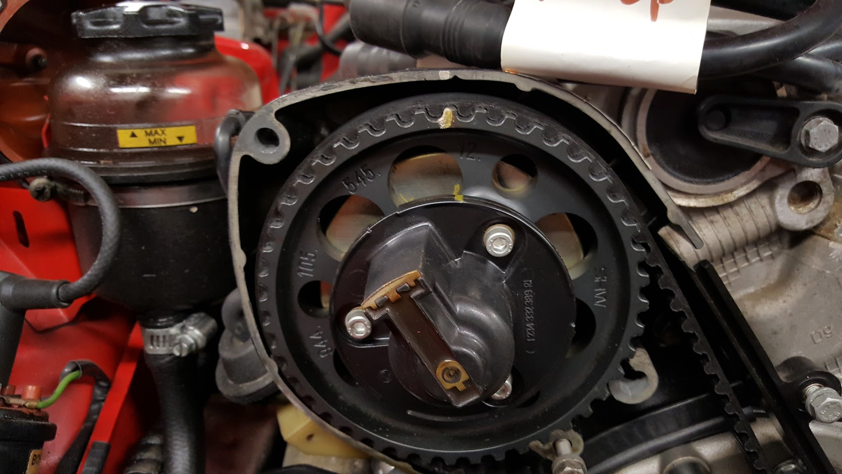
To help you find TDC, here are some pictures. Provided all your belts are still attached, there are at least three marks on the front belts. The easiest is a mark on the cog under the distributor which lines up with a mark on the covering/case. There's a view hole right in the top of the house above/behind the distributor cap. In the picture the cover is off, so no view hole but instead you see the entire cog. You'll see a gold mark which is how I've marked my own because my eyesight is such that a could use some help. The other two marks are on the balance shaft cogs and in order to see those, your plastic cover for the belts would need to be off. Those are shown in the photos too. Above: Notice that the distributor rotor is pointed to about 10:30, which is cylinder #1. The gold mark on my car makes it bloody obvious. Look closely and you will see a little cut mark in the tooth that aligns with the cut mark in the housing.
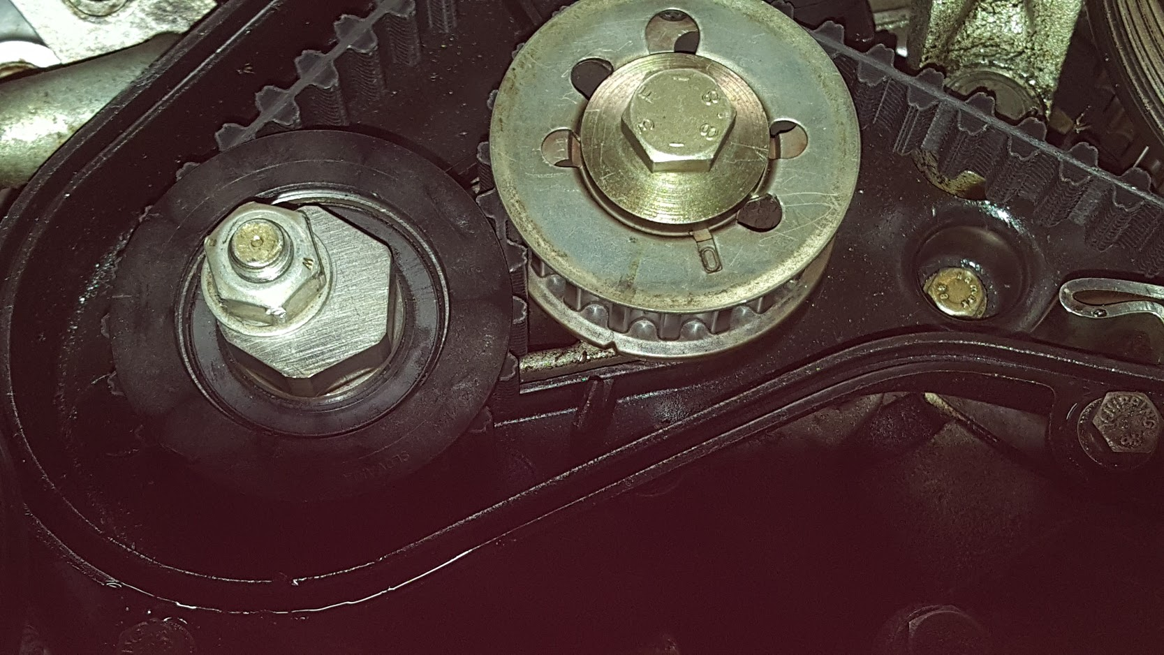
Above: Here's the bottom balance shaft. The cut mark on the back of the cogwheel aligns with the piece of plastic on the housing at almost 7 o'clock.
Above: This is the top balance shaft. Look for the small mark on the back edge of the cog to line up with the small notch in the housing at 12 o'clock.
besides the other notches and marks, there is a small hole in the galvanized flywheel cover that will show a small 'cat eye' when cylinder 1 is at tdc. section 13-10 in the manual.
I remember it being difficult to compress the assembly and I believe there was a check ball where the oil feed entered the vario unit. it might need a bit of oil in it to keep it from moving up and down. it is vented according the manual.
Yea sorry, that was a bad thread title. I am familiar with top dead center but I was curious as to why the Variocam actuator was moving.
I will pressurize it when I get to that stage. I ordered the adapter to hook an air hose up to it.
I had to take off the crank pulley because the balance shaft belt was literally rubbing against the silver guide rail underneath the crank pulley.
When I get to the timing stage I'm sure I'll have a lot of questions for you guys.
Thanks Raj I have read that over and over the last few weeks.
Can you use the intake cams on cylinder #4 for dial indicator measurements as well when cylinder one is at top dead center? It seems a little easier to get the dial indicator to touch the tappet on that end. Would the measurements be the same?
 03-07-2019, 03:38 PM