

Replacing the crank reference sensor
 12-05-2015, 05:28 PM
#1
Rennlist Member
Thread Starter
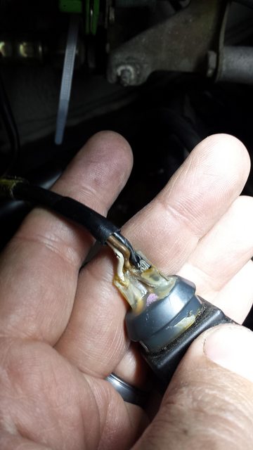
I'm completing a light refurb on my C4. One of the items I found in my engine drop is a heat affected crank ref sensor plug, where the sensor side literally crumbled. Rather than rebuild the plugs (part of the plug is fused in the receptacle) I ordered all new parts.
The newer sensor is a 996 part with a different plug, so the harness connector side must be changed as well.
Parts needed are:
996-606-105-00 [sensor]
999-652-916-49 [plug]
999-652-871-22 [connector]
999-704-161-40 [grommet]
The newer sensor is a 996 part with a different plug, so the harness connector side must be changed as well.
Parts needed are:
996-606-105-00 [sensor]
999-652-916-49 [plug]
999-652-871-22 [connector]
999-704-161-40 [grommet]
 12-05-2015, 05:34 PM
#4
Rennlist Member
Thread Starter
However the wires on my old sensor appear to be White and Black not White and Brown. I assume that's just a manufacturing change, or is it? I get the body back this week and can look at the Harness then. In the meantime has anyone done this and found a similar colour difference?
12-05-2015, 06:41 PM
#6
Nordschleife Master

Why wouldn't you backdate the plug on the sensor side rather than messing with the car's harness? Are the 964-era OE style connector parts still available?
Trending Topics
12-05-2015, 08:33 PM
#9
Rennlist Member
Thread Starter
I believe they are AMP connectors and parts are available. As the male plug fused inside the female plug I needed to do two and even then I'm not sure why it fused in the first place. I thought it was best to start clean because replacing the sensor is easy when the engine is out.
03-19-2016, 04:19 PM
#10
Racer
Hi John,
How did this end up?
was the color coding correct for your installation?
Here is the harness connector I'm going to cut out to replace with the new oval connector.
New parts:
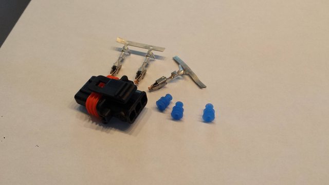
Since I'm doing this very same thing today and wanted to know how it turned out.
Thanks!
How did this end up?
was the color coding correct for your installation?
Here is the harness connector I'm going to cut out to replace with the new oval connector.
New parts:
Since I'm doing this very same thing today and wanted to know how it turned out.
Thanks!
03-19-2016, 05:22 PM
#12
Racer
Did you tin the wires or solder them at all?
Thanks again!
Thanks again!
03-19-2016, 10:59 PM
#14
Racer
I finished installing this but I'm not sure I was successful.
I'm satisfied with the quality of my assembly of the cable connector, but when I crank the motor it still doesn't start. The tachometer needle doesn't move when cranking.
Does this mean I need to take a closer look at the connector I just put together?
Pin1 = white
Pin2 = brown
Pin3 = shielded
I did feel the connectors 'click' when pushing them into the housing. Nothing too difficult in putting it together. Is it possible 3 and 1 should be switched?
Problem is after putting it tougher, it doesn't seem like you can take it apart without destroying it.
Thoughts?