

Hammer First Impressions (long)
 04-03-2006, 11:11 PM
#61
Racer
Join Date: Mar 2006
Location: Joplin, Mo
Posts: 345
Likes: 0
Received 0 Likes
on
0 Posts
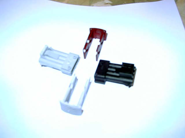
There is a simple way to make a male plug were you do not have to remove the female plug.Place pins in all the receptors and using epoxy putty make an impression.The putty needs to be flat on both sides.Use a rolling pin.Once the putty has cured,remove and drill through the imprints of the pins.A drill press will keep the holes in alinement.Now with the putty you can mark what ever you want to use for the base of the male plug,and drill.Hook-up the wires and incert.It really is fairly simple.I have used this method befor and it work like a charm. 
Jeff522 1990 C2 White/Burgundy
Jeff522 1990 C2 White/Burgundy
 04-03-2006, 11:49 PM
#62
Technical Guru
Rennlist Member
Rennlist Member
Originally Posted by KirkF
I was also thinking of doing the mold that way, (in fact I bought a book on it for another project). Looks like you did a nice job on yours!
Originally Posted by KirkF
Did the 993 use the same 19 pin plug?
04-04-2006, 01:54 AM
#63
Racer

For the pins you might like to look at the Farnell electronic catalogue they list amphenol and AMP connectors and pins. I dont think the connector is the same but they list several pin sizes. The pin part number they have listed are
pin contact farnell part no
2.5mm 379-0952
Don't know if these are the same, but i would guess farnell might be able to supply others made by amphenol or amp. www.farnell.co.uk check out the many pages of connectors there has got to be pins if not the connector there somewhere.
pin contact farnell part no
2.5mm 379-0952
Don't know if these are the same, but i would guess farnell might be able to supply others made by amphenol or amp. www.farnell.co.uk check out the many pages of connectors there has got to be pins if not the connector there somewhere.
Last edited by Laurence Gibbs; 04-04-2006 at 02:12 AM.
04-04-2006, 04:07 AM
#65
Hi All
Jut a few points I've noticed
1 Don't get hung up the 19 pin connector. Just wire another readly available one in parallel with it!
Concours people might have problem with that, but for most of us it aint a problem.
2 If we spent one 1/100th of time working on this as we spend trawling the net. We'd have it finished in no time.
3 There are a lot of people with electronic, programming, and engineering background on this forum.
4 THe 'holy grail' of having your own 'Hammer' is acheiveable if we pool our knowledge and resources.
My own background is industrial electronics (including CAN bus systems ) I have working for me a program developer( C, VB, OCX etc). You know the type, started at the age of ten, lives in his own little world, brilliant guy. Next door at my place of work I have PCB manufacturing plant. That will do one offs and bulk. PIC programming/embeded systems development is not a problem.
Component sourcing also not a problem. Just my 2p worth.
Last edited by robbed666; 04-04-2006 at 05:03 AM.
04-04-2006, 06:09 AM
#66
Instructor
Join Date: May 2002
Location: Leicestershire, England
Posts: 138
Likes: 0
Received 0 Likes
on
0 Posts
Why does this discussion keep going round in circles. A Rennlister wrote hammer replacement software a while ago that works (except for lack of C4 diff lock bleeding) using a standard opt isolated interface which is readilly available on the internet.
He kindly sent me a copy of the software & it works perfectly. However a couple of so called experts butted in with scathing remarks & this kind Rennlister now seems to keep out of the discussion.
Search the archives & you may find what you are all looking for. There is no point reinventing the wheel.
Pete '92 964 RS
04-04-2006, 08:30 AM
#67
Racer
Pete what opto cct did you use?Just wondering if there was something i left out or in that stopped mine from working. It's nice to hear that it does work ok. Having spent some time with mine in the past It's good to know that something works, that way you know it's just a matter of figuring out what i did wrong. For all i know my ecu com chip could be no good. Will have another go soon. Don't know who upset the guy who sent out the software. A shame as his input would help out a lot and I for one was really gratefull for him sending me the software.
04-04-2006, 08:45 AM
#68
Instructor
Join Date: May 2002
Location: Leicestershire, England
Posts: 138
Likes: 0
Received 0 Likes
on
0 Posts
My interface was part of a VW diagnostic package bought a few years ago & the electronics are encapsulated so no schematic is possible. I believe that it is a standard opto based converter similar to those readily available on the internet from suppliers such as http://www.andywhittaker.com/
Also I believe that this design
http://www.planetfall.com/~jeff/obdii/ is the same. Certainly the schematic seems to match the behavior of my interface.
Because TX & RX are tied together at the car end there is scope for problems as there are two ways of dealing with it at the PC end. One way is to always wait for the echo back of any PC TX, the other is the use a spare output signal at the PC end (DTR I think) to enable/disable the PC RX. My interface uses this second method & I was very kindly supplied with a modified version of the software to allow for this.
Originally I checked ot my interface without a car attached. Applied 12v supply at car end & TXed a character from PC & checked for echo back (as effectivly TX & RX are tied together at car end). This is how I then figured how the DTR signal was used.
Hope that this makes some sense & helps
Pete '92 964 RS
04-04-2006, 10:30 AM
#69
Banned

Join Date: Apr 2006
Posts: 11
Likes: 0
Received 0 Likes
on
0 Posts
I read you post on the Hammer. I just put together a PST2 using an IBM laptop. It works on my 964 and my brother-in-laws 996. It's great it displays in color, complete diagrams, readouts and more. I have a couple of fellow Porsche owners that want one of their own but I can't find any more of the old style ( round OBD ) connectors.
Does anyone know where to get the ends that connect to the car so I can make the cables?
Does anyone know where to get the ends that connect to the car so I can make the cables?
04-04-2006, 12:37 PM
#70
"Our cars use obd1 or a close version of. The interface required needs ideally to be dumb and is basically used to convert the 5v pc signal into the 12v car obd signal and vise versa."
Remember, the RS232 PC interface is +/-12V versus USB of 0/5 volts.
The OBDI interface of the 964 requires 0/12 volts. As others have mentioned,
both the circuitry and PC applet have been posted on Rennlist.
Talk to Eric K. as he knows since he built a working unit.
Remember, the RS232 PC interface is +/-12V versus USB of 0/5 volts.
The OBDI interface of the 964 requires 0/12 volts. As others have mentioned,
both the circuitry and PC applet have been posted on Rennlist.
Talk to Eric K. as he knows since he built a working unit.
04-19-2006, 11:18 PM
#71
Instructor

Join Date: Mar 2005
Posts: 124
Likes: 0
Received 0 Likes
on
0 Posts
Originally Posted by dfinnegan
Following are a few first impressions on the Bosch Pocket System Tester, KTS 300 (a.k.a. the Hammer) diagnostic tool which I recently purchased from John Speakes of JDS Porsche in the UK. Porsche calls this the System Tester 9288 in their Shop Manual and include operating instructions for the unit therein.
John was a pleasure to deal with and can be reached via the web at http://www.jdsporsche.com and via email at info@jdsporsche.com. He has these units in stock and sells them refurbished. I'm not sure what the refurbishing includes aside from new batteries.
I paid $1800 US for my unit all in, shipped and insured, to my door. I've read here on Rennlist that the unit takes 6 AA rechargeable batteries worth ~$50 US (thanks Jason!). It came with a power cable, various adpaters for different "mains", a Porsche 19 pin connector cable and a Porsche module. A manual is back ordered, but I received an electronic version, and a paper copy of the English pages. This is sufficient, but I would like to have the official manual. I'm sure it'll arrive in time.
I've had the unit for a couple of weeks, now. Although, due to travel and other commitments, I've only had a short time to work with it.
My first reaction was surprise at how large it was. The case is roughly 18" x 14" x 6" (45cm x 35cm x 15cm) and the unit, itself, is approximately 11" x 5" x 1" (30cm x 10cm x 2.5cm). The case is well designed to protect the unit with a formed plastic insert in which the unit fits quite snuggly. There is space for the power chord, Porsche 19 pin connecting chord, power adapters for various "mains", and documentation. Still, it came in a cardboard box with packing material around it and I'll ship it the same way when the need arises.
The unit can only be run from the battery because the charging cable and the Porsche connector cable use the same port on the unit. There is a second port, but I'm not sure what it's used for. Perhaps a different cable.
The manual is a bit terse and generic, but with a bit of time I came to understand the basic operation of the unit. Once the arrow keys ('<' and '>'), the Next button ('N') and the Help key ('H') are understood, the operation is really quite straight forward. The operating instructions for the Hammer provided within the Porsche Shop Manuals are specific to the 964 and are, therefore, a bit easier to read. Really, they are the same instruction set, just with examples specific to the 964, which was nice for, me, the beginner.
The unit has a four line display and is menu driven. Menus have at most three options selectable via buttons '1', '2' and '3'. Optionally, the '>' key can be used to select more menu items. The '<' key moves back within longer menus. The '>' key is also used to continue when there no real options. The 'N' key is used to complete an operation. The 'H' key brings you to a help screen most any time and the unit can be shutdown from there.
Menus are provided for each of the main systems covered. From memory, they include the DME, PDAS, Alarm, and Heating (CCU) systems. System serial numbers and version numbers are available. Within each system menus are provided to access Fault Memory, Drive links and Inputs.
The Fault Memory menu allows you to retrieve any logged fault conditions within the various systems. These faults can then be cleared, or kept in place. The faults indicated are spelled out in terse english, and the Porsche error codes are available to cross reference with the Shop Manuals.
The Drive links allow you to test various bits within the system. Individual injectors, for example, can be cycled, door locks triggered, etc, etc. Very nice for diagnosing problems. There are quite a few options here.
The Inputs include individual sampling of the values returned from various items within the car's systems. For example, I could test the idle switch and move the gas pedal and read 'open' and 'closed' values to check the switches operation. Same for the Wide Open Throttle (WOT) switch. I could read the Cylinder Heat Temperature (CHT) sensor value, etc, etc. Some inputs can only be read with the engine running, while others can be read with just the ignition turned on. There is a significant difference between what can be done with the ignition alone, and with the engine running. There are also options to sample run-time data such as the Knock Sensor test which samples knocks on a test drive.
My usage so far has included a simple pass through most of the menus. Both with the ignition alone, and with the engine running. I then spent some time trying to diagnose a door locking problem that I'm having. The Hammer reports, within the Alarm System section, a "Position of drives unplausible" error with a DTC code of -14-. A bit terse, to say the least. Cross referencing this with the Shop Manuals, it appears that I have a lock drive motor position sensor problem. That is, the micro switch is not engaging. Or so I believe. Any way, this is the sort of experience that I've had so far as regards a door locking issue. Not significantly more information than what I had assumed through searching Rennlist, but certainly more to the point and removes other possible causes. I expect this will help reduce actual wrench time.
I have also worked through a poor idle condition which I have had for some time now. I believe it was initially caused by an oil overfill by a Porsche Specialist (or his junior mechanic, perhaps!). I tried to clean the MAF/ISV (a couple of times) which did not solve the problem (despite my numb headed fumbling around). I also tried to reset the system by disconnecting the battery (on several occasions). Still no joy. With the Hammer, however, I was able to run a System Adapation and this solved the problem straight away.
What I had was an idle that I thought was low (reading 800rpm on the tach) and dropping to ~600rpm when allowed to fall (e.g. when stopping). The idle recovered, but made down shifting difficult in tight, slow turns and was generally annoying. I also had a bit of hesitation at low rpm. This was very annoying and worse when cold.
With the Hammer I learned that my idle is actually right on at 880rpm even though the tach shows 800rpm. Intereseting. And, after the adaptation, the idle is now nice and steady. Perhaps just a bit higher than before, and can scarsely be seen dipping at all. The hesitation is completely gone; cold or hot. I'm thrilled.
I've also pulled a couple of faults which have confused me. Perhaps I'm using the unit incorrectly, but I've seen a fault from the Heater system which indicates 'rear blower motor stage 1 seized' with a DTC code of '-43-'. Yet, I know that my rear blower runs when the temperature gauge reads ~9pm. It ran while I was testing! I've also seen an 'inside sensor motor signal unplausible' with a DTC of '-45-' from the Heating system. However, it seems that my heat is working fine. Perhaps this is an ignition-only vs an engine running type of thing, or perhaps I actually do have problems. I just don't know yet.
In summary, I am very pleased with the unit and look forward to looking at all of the possible systems, values, inputs and checks.
Cheers,
Dave
05-12-2006, 05:52 PM
#72
Instructor
Check here for some pictures of a quick Hammer test session on a 3.6 transplant: http://forums.pelicanparts.com/showt...hreadid=282401
06-04-2006, 11:10 PM
#73
Banned

Join Date: May 2006
Posts: 15
Likes: 0
Received 0 Likes
on
0 Posts
The hammer is good but a PST2 is better. I plug in my laptop running the PST2 software and it displays onscreen what module it is testing and what the results are. No codes to look up much faster and easier...
06-04-2006, 11:24 PM
#74
Three Wheelin'

Join Date: Dec 2004
Location: Halifax, Nova Scotia , Canada
Posts: 1,779
Likes: 0
Received 0 Likes
on
0 Posts
DrPcar,
Codes ?? On the older cars the Hammer is generally reckoned to be better than the PST2 ! Still if the PST2 stuff was free I can understand your enthusiasm !!
All the best
Geoff
Codes ?? On the older cars the Hammer is generally reckoned to be better than the PST2 ! Still if the PST2 stuff was free I can understand your enthusiasm !!
All the best
Geoff
06-05-2006, 03:59 AM
#75
Instructor
Well, the KTS 500 PCMCIA card for the PST2 is unobtainium. The generic BOSCH version ususally runs between 600$ to 10000$ used depending on which cables come with it. On top of that you need the Porsche PST2 software (a hacked version). The regular SW checks for the PCMCIA device number and won't run on a regular BOSCH KTS 500 card or on a laptop. By the end of the day it is not straightforward at all to get a PST2 to run on a laptop.
And the real Porsche PST2 is not cheap if you can get your hands on one.
Ingo
And the real Porsche PST2 is not cheap if you can get your hands on one.
Ingo