


Head Temp Sensor Replacement (urgent)
Thread Starter
Drifting
Joined: Jul 2005
Posts: 3,363
Likes: 25
From: NY, USA
Once again I am in need of urgent help. I truly look forward to making non-urgent postings again!!
Questions:
1) Can I change the cylider head temperature sensor myself, or does the engine need to be dropped to gain access to it?
2) If I can change the sensor myself is there a DIY instruction set somewhere?
Here is the situation:
I have not resolved my low power and no idle problem.
I have replaced my oxygen sensor and still have the condition where the car idles fine for the first couple of minutes, but then fails to hold an idle at all.
When driven the car hesitates badly above 3k rpm and will only go above 4k rpm if nursed up there with minimal throttle. As soon as I push the throttle even half way down when above 3k rpm the car hesitates and bucks badly.
I have the "check engine" light on all of the time.
I have disconnected the battery for nearly an hour and then reconnected and went for another ride. Same thing.
I have tried to test my Cylinder Head Temperature sensor and believe it is bad. Here is what I've done.
I have purchased a new CHT sensor. Apparently, the original part is no longer available; at least according to Sunset Imports. The new parts they provided are:
993 606 013 00 sensor ($148 retail)
999 650 157 40 connector housing
999 652 871 22 pins (2)
999 704 161 40 rubber grommet (2)
999 652 811 40 housing
This is a sensor, and some parts to build up a connector to match the existing wiring in my car. There is a connector body, some loose pins and little plastic bits to put it all together.
I put a meter on the new cht sensor and got a reading of 2.86k at a low room temp. This is according to spec. Note that the new sensor has just 2 pins.
The connector in the top left engine compartment for my cht has 3 pins. This is connector 4 on page 10-6 of the shop manuals. It is a black connector. Connector 2 is white, 3 is green and 4 is black. I'm fairly certain that I have the correct connector. #4
I put the meter on the pins of this existing connector. Of the 3 pins,
1 - 3 reads zero
1 - 2 reads zero
2 - 3 reads 0.6k
Of course, 1, 2 and 3 depend upon how you hold the connector, but no matter, it appears that I have a bad reading. The temp here is ~50F and the engine was warm (not hot). I'm guessing that I should have been able to read about 1 to 1.5 k.
Now. I followed the wire down toward the front of the car and it drops down and in through a grommet; I think. It's hard to tell as I can't see anything back there.
I' now wondering if I can even gain access to this sensor in order to replace it so I'm looking for input on whether I can change this sensor without dropping the engine and how to do it.
As always, thanks for any and all input.
Cheers,
Dave

Three Wheelin'
Joined: Dec 2004
Posts: 1,779
Likes: 1
From: Halifax, Nova Scotia , Canada
I think you are looking at the wrong plug/socket.It certainly has only 2 pins.
Its a white plug on mine, with brown/black-red wires.Can you look again ?
If the temp sensor goes open circuit the ECU runs on a default value (warm ) and is hard to start cold , a short tells the ECU the motor is at full temp and the same problem only worse but with the motor at normal temperature the driveability is fine.
Super Duper Moderator
Lifetime Rennlist
Member
Lifetime Rennlist
Member

Joined: Nov 2004
Posts: 7,773
Likes: 21
From: YQU
Now I'm a little confused. 
Adrian's book (page 389) says a failed cylinder heat temp sensor that failed high resistance will give a hot start problem.
I had been having some hot start problems (especially at the track) so I was planning to replace the CHT sensor this winter.
Do CHT sensors usually fail high or low resistance and therefore give hot or cold start problems -- or can they go either way? On the same page it also lists a failed CHT sensor as a cold start problem too so could it be either?
Marc
Thread Starter
Drifting
Joined: Jul 2005
Posts: 3,363
Likes: 25
From: NY, USA
I've been looking at this again and think that I've made a mistake. A reading of 0.6k is within the appropriate range afterall. Also, I've been monitoring the value through the DME connector and the values have been changing predictably as the engine cools down.
Still scratching my head.
Still scratching my head.

Burning Brakes
Joined: Mar 2005
Posts: 909
Likes: 0
Just to add to the confusion I am pretty sure mine is a 3 wire connector as well. No doubt it just uses 2 (I have measured mine several times and I'd lay money its the CHT since it varies resistance with temp). I looked up int he shop manual where the connector runs and verified as well.
Three Wheelin'
Joined: Dec 2004
Posts: 1,779
Likes: 1
From: Halifax, Nova Scotia , Canada
All of the temp sensors I have seen have been 2 wire BUT that was in Europe !
I looked up the wire colors so that should help identify the right plug.
Temp sensors used to be a big PIA on the 3.2 which was a 1 wire ! The motor/head acted as the ground.Corrosion led to some pretty strange ECU actions ! The 3.2 replacement sensor is just like a 964 ( 2 wire ) and they are very reliable unless the motor has been pulled and the wire used to hold the motor up!!!
The 964 ECU is pretty smart and if the resistance of the sensor goes high , outside normal range , it substitutes a warm value to keep the motor running .
Cold start isnt so good and full temp running isnt perfect.
If the sensor goes short ,the ECU thinks the Head is at full temp and fuels etc accordingly. This really gives cold start problems but if you can get it going ,once warmed up the motor performance is normal.
If you think the sensor is a problem , warm the motor a bit and then pull the plug and put a paper clip up the two outer contacts to simulate a shorted sensor.
Drive the car and if its no better then you know the sensor isnt the problem.
Hope that helps a bit.
All the best
Geoff
Technical Guru
Rennlist Member
Rennlist Member
Joined: May 2002
Posts: 8,138
Likes: 122
From: USVI
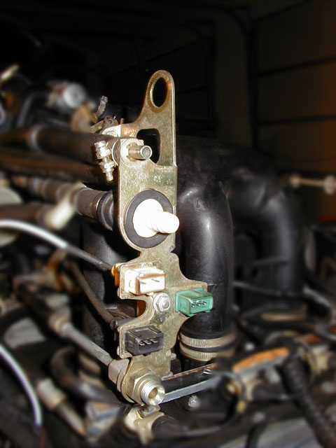
The 3-pin green connector is from the knock sensors, the 3-pin black connector is from the flywheel speed reference sensor and the 2-pin white connector is from the cylinder head temperature sensor.
Trending Topics
Rennlist Stories
The Best Porsche Posts for Porsche Enthusiasts
9 Features and Characteristics That Only Porsche People Understand
Verdad Gallardo
I've Written 500 Rennlist Articles: Here's How Porsche Has Changed Along the Way
Joe Kucinski
10 Most Unnecessary Porsches Ever Built (And Why We Love Them)
Verdad Gallardo
Porsche 911 GT3 S/C vs 718 Spyder RS: 10 Categories, One Winner
Joe Kucinski
This Builder Is Turning Heads With Its Slantnose 911 Creation
Verdad Gallardo
Porsche 911 GT3 Artisan Edition Pays Homage to Japanese Culture
Verdad Gallardo
Porsche Reveals Coupe Variant of the Electric Cayenne With a Fresh Look
Verdad Gallardo
10 Porsche Colors That Have More Personality Than Most People
Verdad Gallardo
Guntherwerks' Final Speedster Creation Is the Ultimate Porsche Restomod
Verdad Gallardo
Thread Starter
Drifting
Joined: Jul 2005
Posts: 3,363
Likes: 25
From: NY, USA
Jason,
No kidding? The shop manual clearly indicats the black connector as the head temp. It has no color but shows
top (white here) - reference mark sensor
middle (green here) - knock sensor
bottom (black here) - temp sensor II
Your picture is exactly my setup. Right down to the brown/black around the white connector!
Note that I have since checked the temp sensor at the DME plug and it appears to be working fine. I'm no longer thinking that is my problem.
Perhaps you could take a look at my thread "Testing DME Relay"?
Thanks so much,
Dave
Technical Guru
Rennlist Member
Rennlist Member
Joined: May 2002
Posts: 8,138
Likes: 122
From: USVI
Originally Posted by dfinnegan
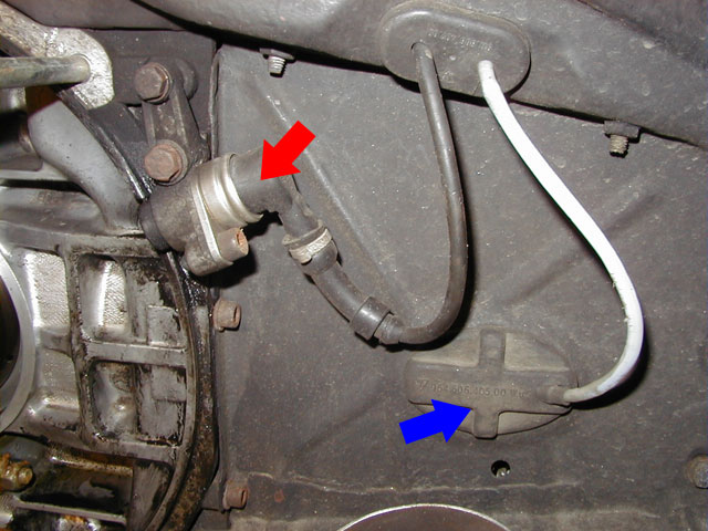
The shop manual clearly indicats the black connector as the head temp.
In the image below the red arrow is pointing to the flywheel speed reference sensor (with black wire & connector) and the blue arrow is pointing to the grommet hiding the CHT sensor (with white wire & connector).
Thread Starter
Drifting
Joined: Jul 2005
Posts: 3,363
Likes: 25
From: NY, USA
Pages 10-6 (picture like yours, but from 90 degrees to the right) and 10-7 with the legend.
Note that I believe that you are correct! I was just surprised to learn that the manual was wrong.
Cheers,
Dave
Note that I believe that you are correct! I was just surprised to learn that the manual was wrong.
Cheers,
Dave
Race Car
Joined: May 2003
Posts: 4,240
Likes: 103
From: SoCal
"Do CHT sensors usually fail high or low resistance and therefore give hot or cold start problems -- or can they go either way" - Marc Shaw -
Temp sensors usually fail in the open condition. The best way to check the temp
is via the DME connector (pins 45 & 48) which checks all the temp wiring not just
to the temp connector.
Check here ( www.systemsc.com/diagnostic.htm ) for troubleshooting info.
Temp sensors usually fail in the open condition. The best way to check the temp
is via the DME connector (pins 45 & 48) which checks all the temp wiring not just
to the temp connector.
Check here ( www.systemsc.com/diagnostic.htm ) for troubleshooting info.
Thread Starter
Drifting
Joined: Jul 2005
Posts: 3,363
Likes: 25
From: NY, USA
Loren,
I have a reference from the official porsche shop manual (page D 24/28 - 12) which indicates that dme pins 45 and 30 are the Engine temperature sensor (NTC II/omega-sign).
Is this incorrect?
I had thought that the engine temp sensor and CHT where one and the same.
Thanks,
Dave
I have a reference from the official porsche shop manual (page D 24/28 - 12) which indicates that dme pins 45 and 30 are the Engine temperature sensor (NTC II/omega-sign).
Is this incorrect?
I had thought that the engine temp sensor and CHT where one and the same.
Thanks,
Dave
Race Car
Joined: May 2003
Posts: 4,240
Likes: 103
From: SoCal
"I have a reference from the official porsche shop manual (page D 24/28 - 12) which indicates that dme pins 45 and 30 are the Engine temperature sensor (NTC II/omega-sign)."
That's correct as there're multiple 964 DME grounds, e.g. 2, 14, 19, 24, 26, 30, & 48.
"I have the "check engine" light on all of the time."
You really need to use the Porsche Hammer & not guess at the faults, i.e. can be
very time consuming & costly.
Remember, the 964 DME system is very reliable except for the ignition system,
i.e. the distributor, cap & rotors, & ignition wiring.
Do the basics:
1. check all powers & grounds
2. check fuel pressure no load & loaded
3. check all dist. areas & plug wires
4. check alt. voltage when prob occurs
5. check for all vacuum & intake leaks