
Arduino Data Logger Project
 08-08-2013, 01:04 AM
#16
Rennlist Member
Thread Starter
Cool stuff Tom. I have everything here but have not touched it yet as I have been focused on baseline tuning my stroker motor. Should start working on the the data logger in the next week or so.
 08-10-2013, 02:48 PM
#17
Rennlist Member
 He said "dingle arm"
08-17-2013, 10:57 PM
He said "dingle arm"
08-17-2013, 10:57 PM
#20
Rennlist Member
Thread Starter
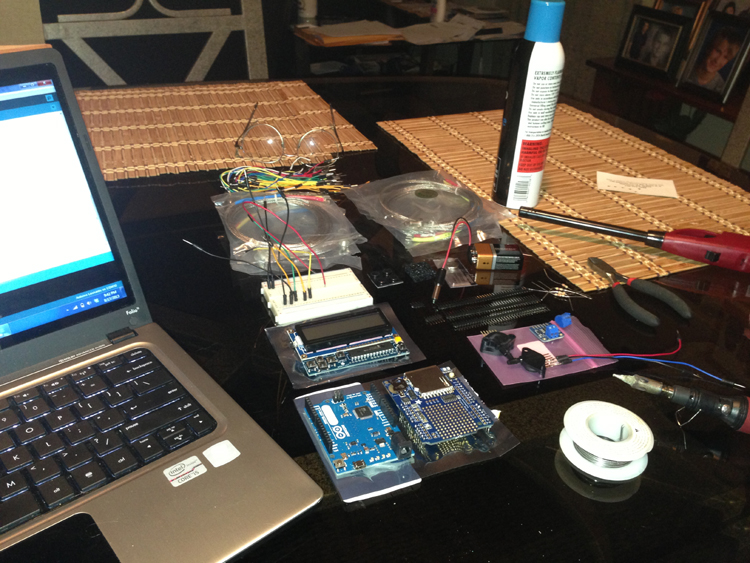
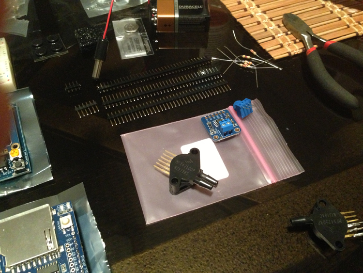
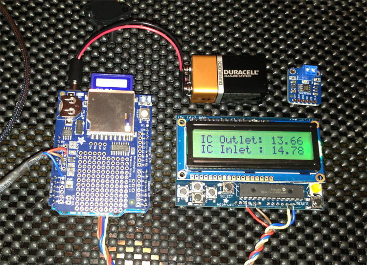
Making progress on my data logger. Pretty fun stuff for sure. Second pic is a differential pressure sensor with a 0-5V output. Looking forward to getting pressure drop numbers at the intercooler, the maf, and throttle body.
08-17-2013, 11:12 PM
#21
Rennlist Member
Now you're talking -- looks like you're having fun and making progress!
I do think the Arduino (or a couple of them) could manage the whole motor, though it would take quite a bit of supporting circuitry -- injection drivers, ignition drivers, ISV driver, etc. -- and some fancy C++ programming...
I do think the Arduino (or a couple of them) could manage the whole motor, though it would take quite a bit of supporting circuitry -- injection drivers, ignition drivers, ISV driver, etc. -- and some fancy C++ programming...
08-18-2013, 11:43 PM
#22
Rennlist Member
Thread Starter
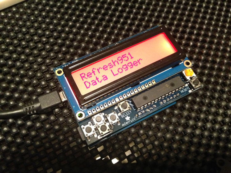
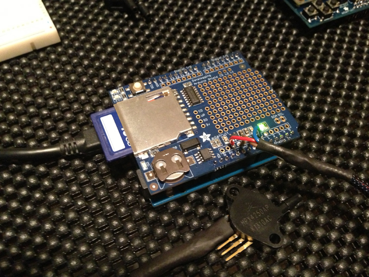
Made a ton of progress on my Arduino data logger today. This thing is amazing and a blast to work on! I should have several analog channels up and running this week. Starting to get the hang of the code. I successfully have pressure sensor data being written to the data shield SD card in time stamped intervals!
 08-20-2013, 01:20 AM
#24
Rennlist Member
Looking great! I vote for a wireless shield for some track-side telemetry! Something in this thread may be helpful as you work up the temp sensors.
http://reutterwerk.com/forums/showth...highlight=temp
At the risk (near certainty) of looking like an old guy who had to walk uphill in the snow to school both ways, here is my first microcontroller project from the 80's -- it's actually an 8051 like in the DME -- except all it could do was say "hello world"... The Arduino is infinitely more useful and accessible and not a minute too soon. Here's to progress...
08-20-2013, 01:50 AM
#25
Rennlist Member
Thread Starter
At the risk (near certainty) of looking like an old guy who had to walk uphill in the snow to school both ways, here is my first microcontroller project from the 80's -- it's actually an 8051 like in the DME -- except all it could do was say "hello world"... The Arduino is infinitely more useful and accessible and not a minute too soon. Here's to progress...

The following users liked this post:
Autobreza (11-08-2023)
08-20-2013, 02:16 AM
#26
Rennlist Member
The Arduino probably has more processing power than all those IBM's combined -- pretty incredible, especially for those who remember the days before personal computing.
My pictures didn't post, so here they are. Hardware from the 80's, with modern day dust on top...
My pictures didn't post, so here they are. Hardware from the 80's, with modern day dust on top...
08-20-2013, 02:42 PM
#27
Three Wheelin'

Nice work Shawn. I've been reading some of the Arduino tutorials in my spare time and it does seem relatively easy, even for someone with limited knowledge of coding. I've done some scripting and beginner Perl stuff back in High School but it's been close to 10 years since I've looked at that stuff. I'm going to order the starter kit and work through some of the sample projects.
And Rob, your car seems to have picked up a rash, you might want to get that looked at
And Rob, your car seems to have picked up a rash, you might want to get that looked at
08-20-2013, 06:14 PM
#28
Rennlist Member
Thread Starter
Tom - I am no EE but rather a gear head, lol. Any chance you could give me specific details on this as then I can then re-use much of your info? Maybe a simple schematic? TIA
08-21-2013, 01:52 AM
#29
Rennlist Member
From RW: "I made up my own driver circuit from Radio Shack that I will detail in a new post. Bascially, just a 5 volt regulator with 2K resistors used as voltage dividers."
Tom - I am no EE but rather a gear head, lol. Any chance you could give me specific details on this as then I can then re-use much of your info? Maybe a simple schematic? TIA
Tom - I am no EE but rather a gear head, lol. Any chance you could give me specific details on this as then I can then re-use much of your info? Maybe a simple schematic? TIA
https://learn.sparkfun.com/tutorials...oltage-divider
As the resistance in the sensor changes, the voltage between the fixed value resistor and the sensor varies. So, for example, when the sensor reads 2k ohms, the voltage from this circuit will be (2k/4k)*5v = 2.5 volts. When the sensor reads 8k ohms, the voltage from this circuit will be (8k/10k)*5v = 4 volts. Knowing that, along with the resistance scale of the sensor, and you can use the Arduino to calculate temps based on the voltages it sees from this circuit. If that doesn't make sense, just let me know.
08-21-2013, 01:16 PM
#30
Rennlist Member
Thread Starter
It is indeed very simple. You just make a voltage divider out of a Radio Shack resistor (2k, 1/4 watt) and the temp sensor, and log the resulting voltage. Read up on voltage dividers here:
https://learn.sparkfun.com/tutorials...oltage-divider
As the resistance in the sensor changes, the voltage between the fixed value resistor and the sensor varies. So, for example, when the sensor reads 2k ohms, the voltage from this circuit will be (2k/4k)*5v = 2.5 volts. When the sensor reads 8k ohms, the voltage from this circuit will be (8k/10k)*5v = 4 volts. Knowing that, along with the resistance scale of the sensor, and you can use the Arduino to calculate temps based on the voltages it sees from this circuit. If that doesn't make sense, just let me know.