When you click on links to various merchants on this site and make a purchase, this can result in this site earning a commission. Affiliate programs and affiliations include, but are not limited to, the eBay Partner Network.
I'm just finishing up a build, and running the HVC II coil. I'm running Rogue hardware. My question is does anyone have a dwell map for this coil, or can someone help me changing the values in the dwell table? Any help would be greatly appreciated!
You need to add a Capacitor to the DME to run the HVC II coil reliably. PM Rogue for details.
Does this table look like stock coil dwell times or I'm looking at wrong place in bin file?
That looks very similar to my dwell map, except most of the values are different. Sorry I don't have stock map to compare, but you're looking at the right map.
Well this is a somewhat old one, but I noticed some things lately that made me feel I had to post a reply.
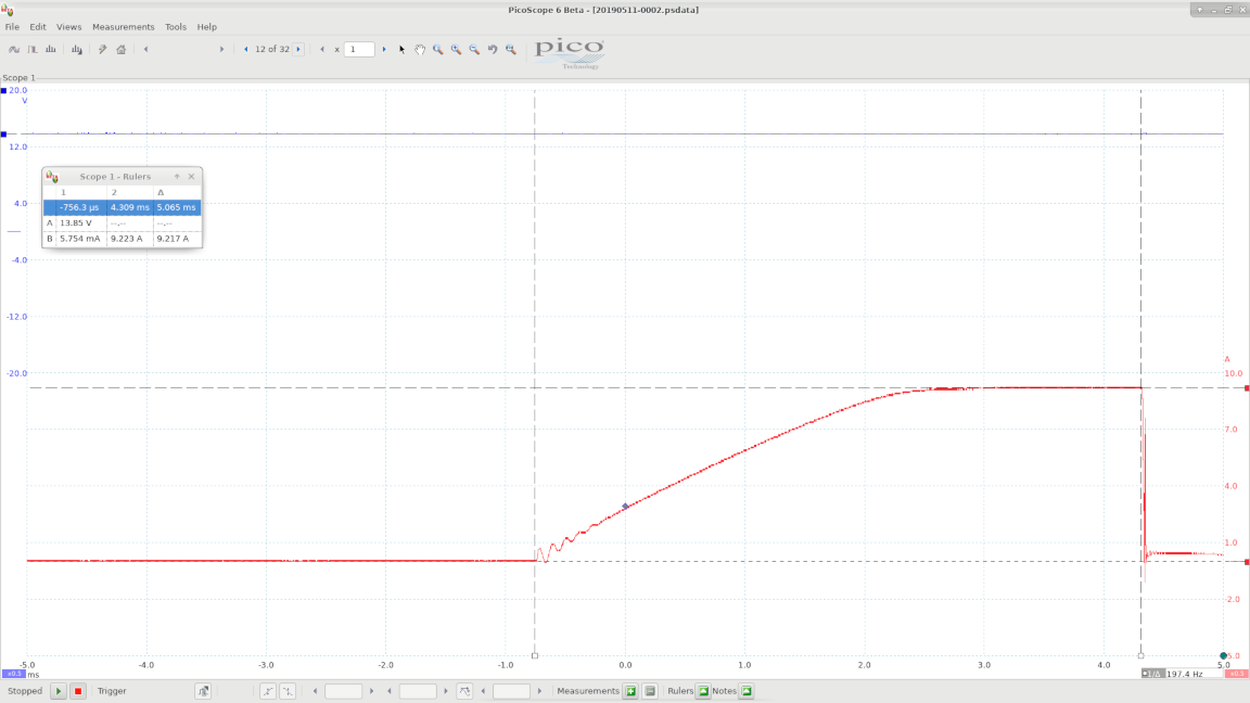
I hooked up a current clamp & oscilloscope to my primary coil wire to see what was going on, and afterwards when I was reading this thread, I noticed that my measurements didn't match up to Josh's scope traces.
As you can see in my image (from idle), the dwell time is around 5ms, and the coil reaches a current of 9A in around 3.8ms or so (the horizontal divisions are 1ms). But in Josh's images, the dwell time is more like 10ms and the charge time to reach 9A is 6.5ms. He stated that he used a voltage of 13.8, and that's what I have too (the blue trace in my image, Channel A in the "Rulers" window).
I was curious to know what might have caused this difference - what could be wrong with my car that would make the coil charge so fast? But after looking into it a bit, I'm pretty sure Josh made a big mistake with his measurements.
Firstly, it shouldn't take 6.5ms to charge the coil. Using the formula here (T = Isat*L/V) with the 5.85mH inductance he measured for the stock coil, it should take around 3.8ms (9A * 5.85mH / 13.8V) as long as there isn't excessive resistance.
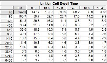
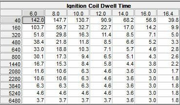
Secondly, look at the dwell map (it's posted near the end of this thread but I'll include it here anyway). There isn't anything near 10ms within the range of normal, stable rpm with typical voltages. And this isn't something that you can change by using the wrong coil - the DME decides the dwell time based on rpm and voltage.
My trace is a good match for the 14V range at idle speeds - 5.1ms according to the map.
Now the reason this matters is that the whole premise of the thread was the notion that above 4000rpm or so, the available dwell time is less than 6.5ms, and therefore the stock coil can't reach it's maximum current of 9A. Therefore, the theory goes, you're better off with a coil that charges faster even it actually delivers less energy at peak. But since it appears that it actually only takes ~3.8ms for the stock coil to reach max current, this means that there's enough dwell time available right up into the 6000s. So unless I'm missing something, there's actually no situation where the MSD Blaster coil can be an improvement. It's always going to have less energy, at any rpm.
I could well be wrong about something here, but the fact that my 3.8ms measurement is backed up by the inductance formula I mentioned, and by the DME's own dwell maps (which use 5ms or less even at rpm values that would permit far more dwell time if it was needed) makes me think I'm right.
Don't get me wrong, I don't want to sound like I'm criticizing the rest of the stuff he posted here - I'm sure that it's great stuff, and certainly way beyond my knowledge. In any case it's a great overview of the system, and a good warning to people to be careful when experimenting with different coils. But I thought I had to post this because I've seen a lot of people discussing the MSD coil here on the basis that the stock coil is somehow sub-optimal, and now I think this is ultimately all based on an incorrect measurement.
This leaves the question: how did Josh end up with that scope trace? Well I can't know for sure, and he doesn't seem to post here any more. This same article is on his website, but it doesn't have any contact info that I can see. But I think the key is in the dwell time: that has to come from the map. There's only a few conditions that would make the DME use 10ms, and my guess is that the test voltage was really around 8-10V. I think this because it explains the dwell time and the actual charge time - plugging 8V into the inductance formula above does indeed result in ~6.5ms. Of course this would mean that the test probably wasn't done on a car, but using a bench test setup of some kind, and the voltage just wasn't where he thought it was.
John, thanks for taking the time to post all that -- always great to see real first-hand test data. I'm putting this on my list to see if I can replicate your findings (or Josh's) for what it's worth, but I tend to work slowly. The Bosch system did so much, so well, with such little processing power, you do have to seriously wonder if they really under-charged the coil at higher RPMs. I opted to use an MSD ignition box matched to their coil to eliminate the guess work, and am mindful that some of the more modern systems are closed-loop in the sense that they monitor the coil charge and always give it just the dwell it needs. That might be a cool project for the 951 someday. In the meantime, I'll see if I can do some testing too.
John, thanks for taking the time to post all that -- always great to see real first-hand test data. I'm putting this on my list to see if I can replicate your findings (or Josh's) for what it's worth, but I tend to work slowly. The Bosch system did so much, so well, with such little processing power, you do have to seriously wonder if they really under-charged the coil at higher RPMs. I opted to use an MSD ignition box matched to their coil to eliminate the guess work, and am mindful that some of the more modern systems are closed-loop in the sense that they monitor the coil charge and always give it just the dwell it needs. That might be a cool project for the 951 someday. In the meantime, I'll see if I can do some testing too.
That's great, I'm looking forward to seeing your results!
Great post, lots of excellent info, made me relook at my setup.
Basic question, on my standalone one of the ECU parameters is Ignition fire edge.
Quoting the manual it says: "This parameter must be set according to the igniter module you are using. EMS igniters and most OEM igniters work with a falling firing edge. This means that the ignition output of the ECU is held at a high voltage for the duration of the dwell period and then switched off when the coil needs to fire. Rising edge modules work in the opposite manner. It is important to set this correctly to prevent coils and igniters from being overloaded."
So reading this introduction to the post the coil is at 12v and the DME pulls it down to start charging and lets it go back to 12v when charged, so is this a "rising edge" setting I should have?
thanks
mike
p.s I currently have it set to falling edge and working fine, however it could be damaging...
Thanks but as far as I am aware the ingniter is part of the car not the ECU, so its here its a Porsche part, thats why you have to specify its characteristic to the ECU.
But I thought I had to post this because I've seen a lot of people discussing the MSD coil here on the basis that the stock coil is somehow sub-optimal, and now I think this is ultimately all based on an incorrect measurement.
the coil could only really be suboptimal if the fire was blowing out at high boost/high rpm.
spark energy is a good marketing term but the spark either lights the gas or it doesnt.
no one really reports any functional issues there.
though going to waste spark or coil-on-plug lets you open the gap up much wider for better idling/burning characteristics...
Bringing up this thread again in hopes of finding some users of the 8253 HVCII coil. I've been using the MSD6A box with 8253 coil for years and have been happy with it. More recently, I've noticed the tell-tale signs of weak ignition when running the MSD stuff. When I revert to the DME and stock coil, the issue goes away. So, I'm trying to figure out if the MSD6A box or the coil is at fault.
Can anyone with the 8253 measure the resistance between the 1) the main output post and the + terminal; 2) the main output post and the - terminal; and 3) between the - and + terminals? Mine don't match the official specs, so the coil is suspect, but it's not 'that' far off, so it makes me wonder what others are seeing?
p.s., I can't seem to log in to the msd/holly forum and the admins don't respond when I ask for help . Otherwise, I'd be asking there...
the DME decides the dwell time based on rpm and voltage.
-John
What advantage is there for the dwell time be RPM dependent. I'm far from being a sparky. I get the voltage part. So lets say a constant Voltage could be achieved, why not use the shortest dwell time of 3.8ms for all RPMs? Heat generation in the coil driver?
What advantage is there for the dwell time be RPM dependent. I'm far from being a sparky. I get the voltage part. So lets say a constant Voltage could be achieved, why not use the shortest dwell time of 3.8ms for all RPMs? Heat generation in the coil driver?
Thanks
Mike G.
There's a few reasons to keep the dwell short. Yes, the coil can get hot if it's constantly running at max dwell and that will reduce the lifespan of the coil. Constantly running max amps across the spark plug gap and the cap/rotor gap will also reduce their lifespan since a hot spark will erode the electrodes, plus it will oxidize the terminals in the cap and rotor, reducing their conductivity. But the engine needs more spark energy at peak torque since that's when the air/fuel charge is at it's greatest density, and it's hard to shoot a spark across the plug gap when the plug gap is full of low-conductivity air and fuel. So the stock DME has low dwell time at idle and low rpm to keep the coil cool and improve the durability of the ignition components while using higher dwell time at higher rpm to ensure a good spark and complete combustion at max power.

 04-26-2016, 11:45 PM


 The Bosch system did so much, so well, with such little processing power, you do have to seriously wonder if they really under-charged the coil at higher RPMs. I opted to use an MSD ignition box matched to their coil to eliminate the guess work, and am mindful that some of the more modern systems are closed-loop in the sense that they monitor the coil charge and always give it just the dwell it needs. That might be a cool project for the 951 someday. In the meantime, I'll see if I can do some testing too.
  . Otherwise, I'd be asking there...