looking for photos of clearance btw. turbo inlet pipe and bodyy
 06-03-2012, 07:21 PM
#1
Burning Brakes
Thread Starter

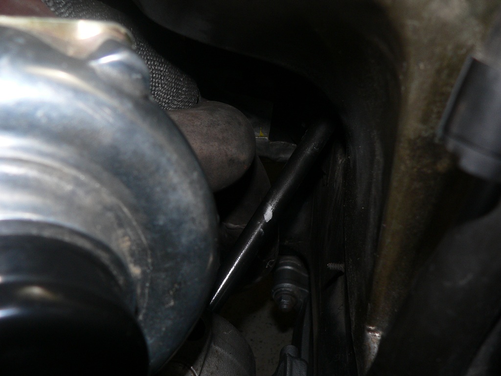
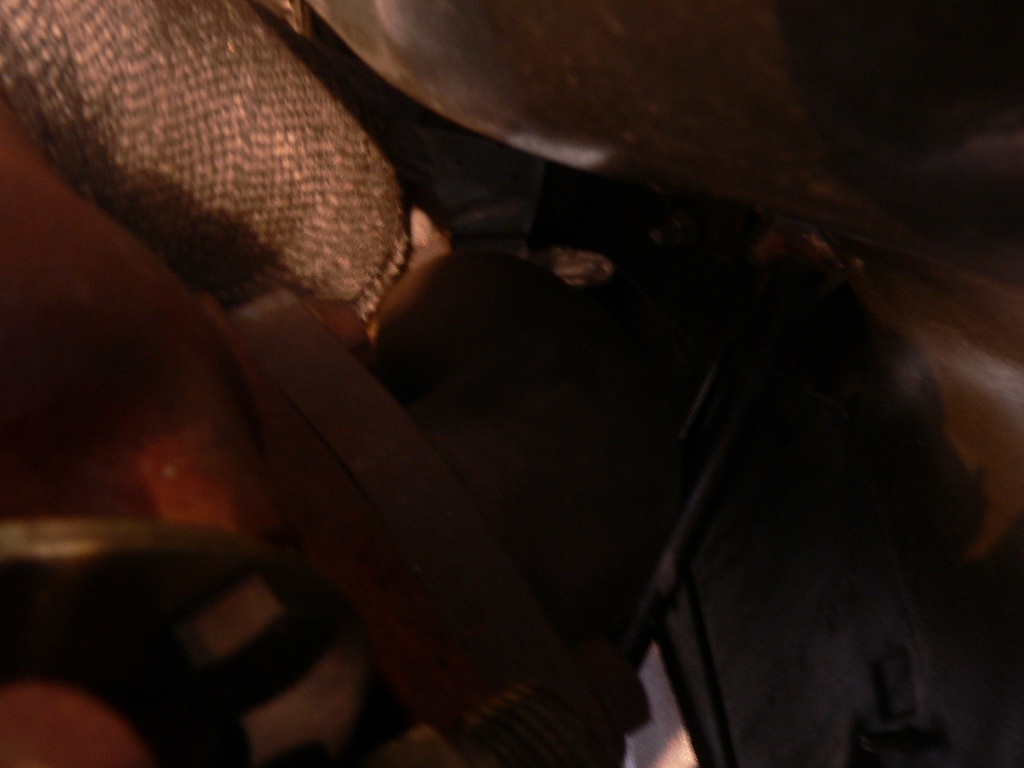
I'm constructing new inlet pipes for my turbonetics turbo. I've had the engine out for so long I no longer remember the clearances around the turbo. If anyone has any photos of the area around the turbo, specifically the clearances between the inlet pipe and the body, I would like to see them.
The picture shows an early mock up. The down pipe will be replaced with a new v-band custom pipe. The inlet pipe will be made to mate with the flange as squarely as possible. The placement of the steering shaft is very annoying as it blocks access to the inlet port directly from below.
Thanks.
The picture shows an early mock up. The down pipe will be replaced with a new v-band custom pipe. The inlet pipe will be made to mate with the flange as squarely as possible. The placement of the steering shaft is very annoying as it blocks access to the inlet port directly from below.
Thanks.
Last edited by bebbetufs; 06-04-2012 at 05:21 AM.

 06-04-2012, 05:19 AM
#6
Burning Brakes
Thread Starter
Thanks Paul.
@kev: My heat shields are on the floor waiting for room to go on as soon as I cut the down pipe and begin the fitting process.
Paul. How did yo manage to come straight up to the inlet flange without interfering with the intermediate steering shaft? Also, how was it to cut the pipe in the insulated part, what exactly is the insulation used on the x-pipe, is it asbestos? Was it OK to weld a flange very close to it, or did you have to scrape it out from the gap to avoid it ruining the weld?
Do you remember what radii bends you bought?
Last edited by bebbetufs; 06-04-2012 at 05:35 AM.
06-04-2012, 05:51 AM
#7
Professional Hoon
Rennlist Member
Rennlist Member
Join Date: Jan 2010
Location: Melbourne, Australia
Posts: 7,090
Likes: 0
Received 4 Likes
on
4 Posts
Thanks Paul.
@kev: My heat shields are on the floor waiting for room to go on as soon as I cut the down pipe and begin the fitting process.
Paul. How did yo manage to come straight up to the inlet flange without interfering with the intermediate steering shaft? Also, how was it to cut the pipe in the insulated part, what exactly is the insulation used on the x-pipe, is it asbestos? Was it OK to weld a flange very close to it, or did you have to scrape it out from the gap to avoid it ruining the weld?
Do you remember what radii bends you bought?
@kev: My heat shields are on the floor waiting for room to go on as soon as I cut the down pipe and begin the fitting process.
Paul. How did yo manage to come straight up to the inlet flange without interfering with the intermediate steering shaft? Also, how was it to cut the pipe in the insulated part, what exactly is the insulation used on the x-pipe, is it asbestos? Was it OK to weld a flange very close to it, or did you have to scrape it out from the gap to avoid it ruining the weld?
Do you remember what radii bends you bought?
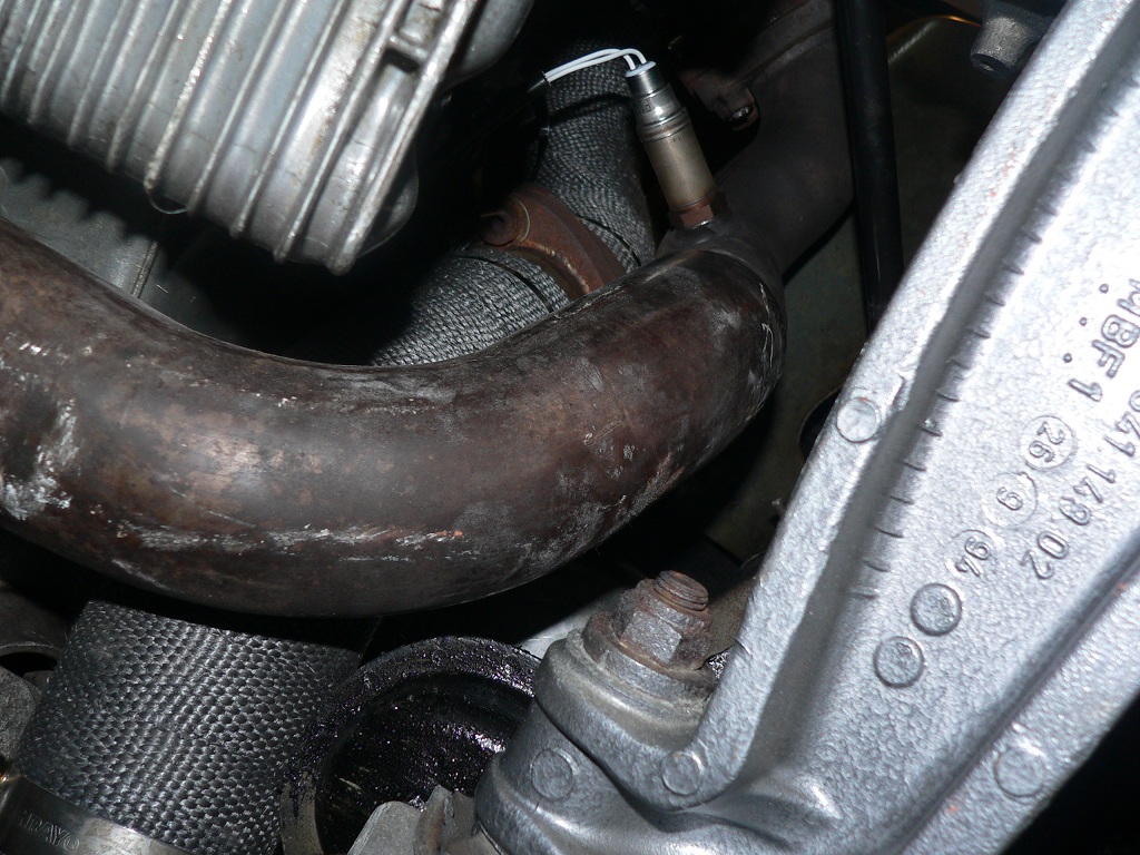
if you're talking about the white sheet around the tube, that's ceramic head wrap found at exhaust shops. i put that on last after the welding was done.
It was just a 90 degree elbo and a straight tube to the x-over.
So i don't think you can go straight how i did it, you could try and modify the stock x-over right at the last bend before the flange with a new 90 degree which will need to be modded to fit.
Trending Topics
06-04-2012, 05:59 AM
#8
Burning Brakes
Thread Starter
RHD explains it. Funny I did not think of that, and I could not see the steering shaft in your pictures.
What I meant was the insulation of the stock cross pipe. It looks like you cut it at the insulated part.
What I meant was the insulation of the stock cross pipe. It looks like you cut it at the insulated part.
06-04-2012, 07:42 AM
#9
Professional Hoon
Rennlist Member
Rennlist Member
Join Date: Jan 2010
Location: Melbourne, Australia
Posts: 7,090
Likes: 0
Received 4 Likes
on
4 Posts
that was probably a benefit having a RHD but i have to make really custom equal length headers which would be the downside if i decide on that.
oh, there was nothing in there. it was more of a head shield.
oh, there was nothing in there. it was more of a head shield.
06-04-2012, 08:14 AM
#10
Burning Brakes
Thread Starter
Ok Thanks. Interesting about the heat shield. I have bought a complete set of ceramic coatings and will coat the entire exhaust. I have been wondering if I should keep the steel wrapping on when doing this or not. Perhaps it would be better to remove it so I can coat the actual pipe. I could possibly tack weld it back on afterwards and coat that as well to keep even more heat in the pipe. Do you think this could get too hot for the turbo?
Also where did you stick your stock O2 sensor?
Also where did you stick your stock O2 sensor?
06-04-2012, 08:34 AM
#11
Professional Hoon
Rennlist Member
Rennlist Member
Join Date: Jan 2010
Location: Melbourne, Australia
Posts: 7,090
Likes: 0
Received 4 Likes
on
4 Posts
i doubt it'll get to hot for the turbo. it'll most likely run cooler then the stock one since it can flow more exhaust though it easier.
stock o2 is in the same location as stock. we got the old bung and re welded it.
stock o2 is in the same location as stock. we got the old bung and re welded it.
06-04-2012, 09:02 AM
#12
Burning Brakes
Thread Starter
I did not think about the flowing more bit, but if it is flowing more it is also producing more hot air so would that not cancel itself out?
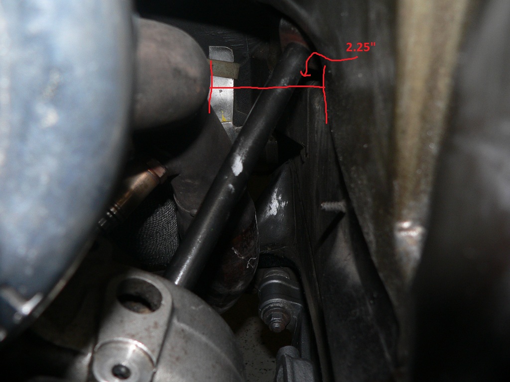
What diameter tube did you use for inlet pipe and roughly how much space did end up with between the final bend into the turbo inlet and the body? I'm wondering if I can calculate the distances from looking at your photos.
What diameter tube did you use for inlet pipe and roughly how much space did end up with between the final bend into the turbo inlet and the body? I'm wondering if I can calculate the distances from looking at your photos.
06-04-2012, 09:22 AM
#13
Professional Hoon
Rennlist Member
Rennlist Member
Join Date: Jan 2010
Location: Melbourne, Australia
Posts: 7,090
Likes: 0
Received 4 Likes
on
4 Posts
you'll be alright with heat since these turbos are made to be bolted straight to the exhaust manifold.
I cannot remember sizes from the top of my head since it was a metric size. but it was exactly the same size as the original pipe. its a bit more then 2" IICR
I really don't remember distances. but i had plenty of room from the heat shield and the exhaust
I cannot remember sizes from the top of my head since it was a metric size. but it was exactly the same size as the original pipe. its a bit more then 2" IICR
I really don't remember distances. but i had plenty of room from the heat shield and the exhaust
06-04-2012, 09:33 AM
#14
Burning Brakes
Thread Starter
Thank you Paul. You have been very helpful.
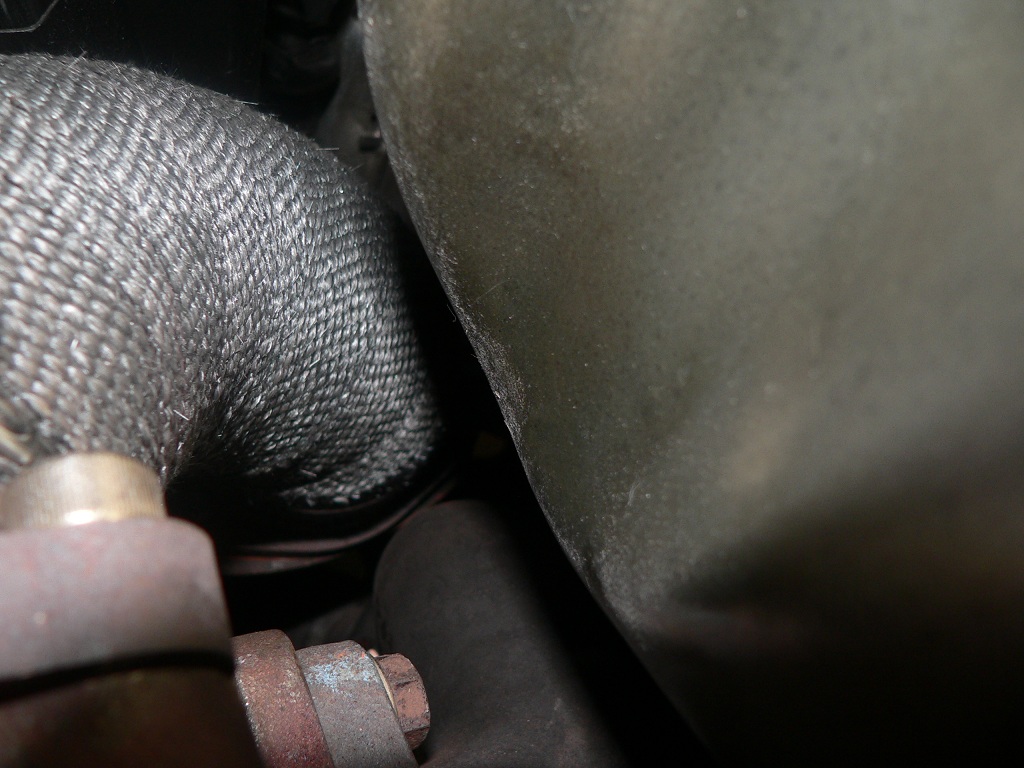
If anyone has the approx distance from the final inlet elbow to the body heat shield that would be of great help. I'm wondering if there is a bit more room available than what it looks like when looking at the stock x-pipe.
If anyone has the approx distance from the final inlet elbow to the body heat shield that would be of great help. I'm wondering if there is a bit more room available than what it looks like when looking at the stock x-pipe.