
ITB Intake Manifold interest
 09-16-2009, 07:45 AM
#61
Race Car
5.0L, 32 valves and 400HP/400TQ. Very similar HP/TQ figures to the car I sold, but without a whining supercharger. I might have to buy another one if the economy comes back.
Any thoughts on what Shelby or Roush invest on R&D on intake manifolds?
I would image in the case of Roush, the R&D cost is spread out over a large number of units keeping prices relatively low. Since Ford warranties the Roush upgrades for 3 years or 36,000 miles, I would also guess that Ford engineers were involved in the R&D process and probably made their engineering labs and computer systems available. Very interesting topic.
My experience with Roush is not very positive. The people at Ford with whom they historically work are people in marketing, not engineering.
 09-16-2009, 07:55 AM
#62
Three Wheelin'

Join Date: Jan 2002
Posts: 1,258
Likes: 0
Received 0 Likes
on
0 Posts
I have seen the pictures of the prototype � its pretty nice. The most critical part of any multi throttle set up is the linkage � if there is any slop or misalignment the idle will truly suck. On carbs you can get away with it because each throttle is self metering � but with fuel injection the throttles have to be perfect or you will have a huge A/F variance at idle and small throttle openings.
You put a set of carb sticks (a column with 4 mercury vacuum gauges) and adjust them until the all have nearly the same vacuum.
Come on guys. This isn't as hard as you think. Motorcycles (which have smaller engines that are harder to get EFI to work well on) all have individual throttle bodies. In fact, you could probably adapt a motorcycle system bu changing center to center spacing.
-Dana
09-16-2009, 08:51 AM
#63
Addict
Rennlist Member
Rennlist Small
Business Sponsor
Rennlist Member
Rennlist Small
Business Sponsor

Some adjustable linkages add to the slop. Set them and 5 minutes later they are slightly different. They all have some adjustability but not all are good!
09-16-2009, 10:57 AM
#64
Basic Sponsor
Rennlist
Site Sponsor
Rennlist
Site Sponsor
Thread Starter
67, Interesting read. Sounds like you did some good work there, although I'm not getting that you worked on a boosted car or with a Porsche engine in your projects. When it comes to a boosted engine, and worse a boosted Porsche engine, you don't have much luck making predictions on paper. And just because something may work on one engine type, doesn't mean it's going to carry over to another. For example, trying to size a turbo on paper or with compressor charts for a Porsche engine is a waste of time. You have to build it, try it, and change if it doesn't do what you want.
That's why we have a engine dyno. We can play with this and make changes quickly without the confines of a engine bay and compare results. We can built plywood plenums only good for a couple pulls if we want and try another size.
There are several examples of cars out there running ITB intakes that are very respectable. Kokeln built two of them. Many of you know of others. You can see them in one of the threads showing all types of high end 951's. As far as we know, there is not a available production part, other then the JME intake for around 6k. I don't think he will build you one unless you buy a complete engine. We are trying to offer something for half that or less if it works out in the end.
It's not for sale yet. As the thread stated, we are looking for the level of interest in a product like this.
We will have fun with it even if we never reproduce or build a single one for sale, although we already have a couple of verbal commitments. I'm sure Rob would love to have one on his build just for the cool factor.
I can tell you there isn't a production intake out there that will currently feed a big valve correctly ported 8v head with a big lift cam that anybody builds, (with the possible exception of the JME, although that's not known), and nothing for a 16v either. This may be the first to be built and offered to anybody.
__________________
Mike or Dave Lindsey
www.lindseyracing.com
U.S. 1-877-943-3565
Other 1-405-947-0137
Mike or Dave Lindsey
www.lindseyracing.com
U.S. 1-877-943-3565
Other 1-405-947-0137
09-16-2009, 11:09 AM
#65
Basic Sponsor
Rennlist
Site Sponsor
Rennlist
Site Sponsor
Thread Starter
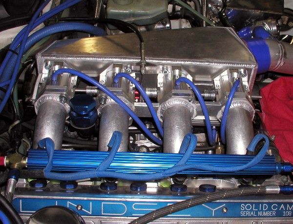
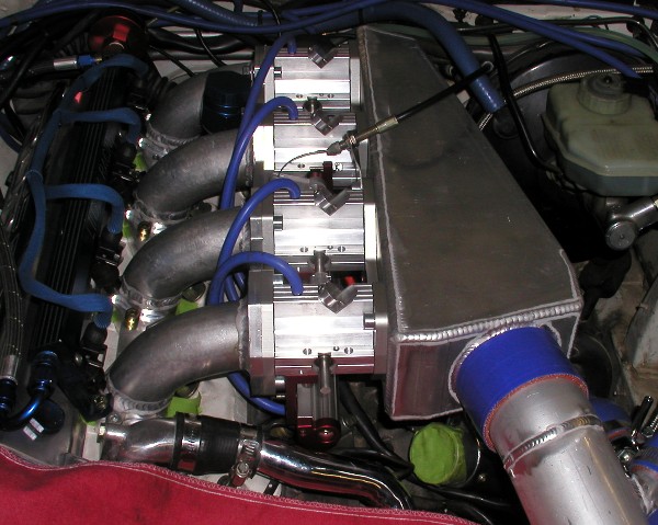
Here are a couple of views. This is a proto-type built for testing, and a production
part would be improved in appearance where it can be. Building this one has
given us new ideas already although it doesn't make sense to make improvements
at this stage. If it's a good seller, we would have either a cast or composite plenum built. This fabricated one is easy to build, and can be easily changed on the next one. Can't do that on a
part out of a mold and you buy the tooling for us with the cost!
09-16-2009, 01:51 PM
#69
Nordschleife Master
09-16-2009, 01:56 PM
#70
Basic Sponsor
Rennlist
Site Sponsor
Rennlist
Site Sponsor
Thread Starter
Thanks Duke. DDP, yes, that's the oil fill. We will make a new cap, but that's good for now.
Inside picture? Not much to see. That plenum plate (the back of the welded plenum that the ITB's bolt to,
is 3/8" thick, with a nice big radius machined into it like our other intake like you see here
http://www.lindseyracing.com/pics/intake7.jpg.)
We have a 45mm bore for blade, forward of that 1/4", it then tapers up to 50mm at the front in the ITB.
then we have our big radius on the plenum plate. So it's in effect a velocity stack without
the side flow to other runner interuption. Just doesn't look like until you think about it, and
realize it's the inside of one.
It's a little to early for dyno charts, but eventually there should be.
Last edited by Mike Lindsey; 09-16-2009 at 03:00 PM.
09-16-2009, 03:13 PM
#71
Race Car
...................although I'm not getting that you worked on a boosted car or with a Porsche engine in your projects. When it comes to a boosted engine, and worse a boosted Porsche engine, you don't have much luck making predictions on paper. And just because something may work on one engine type, doesn't mean it's going to carry over to another.
At the end of the day, the laws of physics that limit all engines do so irresepective of make. Furthermore, Porsche actually designed the initial Modular (the engine I did all of my work on), as well as the Duratech, and a few different engines for Harley Davidson. Most of my personal work has been on a boosted engine (Ford's old 2.3 turbo), more recently an N/A BMW application. You would probably be surprised to learn how much benchmarking there is in the industry. FWIW, the 944 had the best flow coefficients of any port Ford had measured into the early 2000's. And like I said, Porshce did the earliest work on the Modular. Trust me, I'm not just doing the old shade tree hot rodder approach of saying "well, this works on a Chebby, so do it." I look down to the shape of the valve seat, and what the velocity profile over that interface looks like. AIr doesn't give a rats butt who cast the part, its flow through the orifice is governed by the same phenomena.
Again, y'all have a great reputation, and I don't doubt that you verify what you are trying to do. I'm not questioning that, I was trying to point out as a result of some of the other postings that there is a lot to designing an intake. However, thinking the engineering behind it all can be dismissed because it is a boosted Porsche is very flawed. Just look at how much more powerful engines have become in the past couple of decades. In the 80's, it was anecdotal followed by dyno verfication. Now, we are using very mature and complicated tools in the design process, and getting MUCH better results.
By the way, the phenomenon most responsible for intake tuning, Helmholz resonance, is not governed by pressure (i.e. boost levels). Which is why guys like Corky Bell, who recommend just running stacks and cranking up the boost, are misguided. It is RPM, runner length, runner diameter, compression ratio, cylinder volume, and speed of sound (F(temperature, gamma)).
However, density IS a factor in the Reynolds number calculation, though the range is so tight, it doesn't have much of an impact. But, upsizing very slighty to account for that is a plausible approach. This is primarily a peak flow, i.e. RPM, concern. But as I said earlier, it all starts at the valve, so the size should really not be a variable without an entire system look.
The intake looks good. If you want some feedback, I'd make sure you have sufficient room above the bellmouth for runner #4. You need to have a volume above the entry that will fit a sphere with a radius 1.5 times the radius of the runner. The "picture" is a scoop of ice cream in a cone (where part is down in the runner). You may, it is hard to tell from the picture. If you can make the plenum surfaces less flat, that would help with noise and durability (fatigue), as well.
09-16-2009, 03:36 PM
#72
Basic Sponsor
Rennlist
Site Sponsor
Rennlist
Site Sponsor
Thread Starter
67, thanks for the input.
You can talk to 10 people that build or have built intakes and get a little different take on what to do.
The plenum was approached with 1.5 times the CI of the engine. That seems to be a
good rule of thumb and a good place to start. We also have to deal with the confines of
the chassis, and accessories that are planned. We can go wider and thicker, if needed. We have plenty of room at the back and more when we add our brake system down the road.
If this goes in a street car with all the regular goodies, we sell more.
We tested another companies intake once, and it was a front feed intake. It was not at all
even, especially the front runner. Something like 50 CFM short and it had a similar plenum. Our
unit has proved balanced well on a flow bench, so we are not squeezing to much at the back with that test. Further testing with the dyno will tell us what's happening under boost since that's about the only
way to move that kind of air at that pressure.
On our dyno, we have temp probes on all cylinders and can log the data. Matched injectors and batch firing doesn't leave to many other reasons to have unmatched flow.
Last edited by Mike Lindsey; 09-16-2009 at 03:53 PM.
 09-16-2009, 04:18 PM
#74
Basic Sponsor
Rennlist
Site Sponsor
Rennlist
Site Sponsor
Thread Starter
Once done, we plug all the parts into our computer and assign individual part
numbers, vendors, costs, etc... Then look at the labor, welding, assembly, tooling, etc...
and figure a mark up allowing for Jobber pricing. That's a big job in itself, and haven't started yet.
A waste of time if we don't end up building it.
I'll say again, we are shooting for about 1/2 or less the other intake. Just not
sure how straight we are shooting yet!
09-16-2009, 04:31 PM
#75
Instructor

Join Date: Dec 2008
Location: bahrain
Posts: 183
Likes: 0
Received 0 Likes
on
0 Posts
thats very good work David.
will you be making any for the 968?
i always felt that the mechanical limiting factor to have 100-110 BHP /LITRE
is the air in ,limited by the 60 mm trottle body.
similar engines with smaller valves cams and 2 litre capacities
made 250 to 270 bhp on 45 mm bodies.
A simillar 2.4 Nissan engine on 50mm carbs with 45 mm venturi makes 270 bhp
at 7500 rpm, so a similar trottle body for the 3 litre 968 should be making
appx 330 BHP at 6700 rpm red line with added fuelling , plus the added
variocam benefit.
The TURBO manifold i bought from you for my 951 is excelent
and i am sure that this new one will have excellent results also.
Put me down for one for my 968.although i personally feel that 48 mm bodies may be a bit on the wide side.