When you click on links to various merchants on this site and make a purchase, this can result in this site earning a commission. Affiliate programs and affiliations include, but are not limited to, the eBay Partner Network.
Also check out a product called LilKnockMeter. Seems viable, and you can "tune" out the ambient noise from normal engine operation.
If you decide not to use a crank mounted trigger wheel let me know - I am working on a 'trigger plate' design which replaces the distributor and provides both a speed and reference signal.
Hey Scott, great videos! Thanks for sharing. When I first saw your post, I was thinking to mention some of the diagrams I put together when I did my harness. But then I spied a copy of my harness dimensions diagram in your stack of papers! Glad to see it's been of some use.
Some random thoughts as I watched the videos:
- I see you've already wired the injector harness, so this thought is probably a little too late: I placed the junctions for the injector signal wires on the other side of the snorkel, with the theory that this would make it easier to transition to a full sequential setup down the road should I want that. Obviously doing this would entail updating to a more capable ECU. But I figured this process would be easier if I didn't have to run new wires through the snorkel.
- In a similar vein, I would run some extra wires through the snorkel for future use (e.g. additional temp sensors, cam position sensor, EGT, etc.). In hindsight I should have run a few more than I did.
- What's your plan for the speed and ref sensor wires? I'm currently using a front trigger wheel (GSF 36-1). But my plan is to switch away from microsquirt at some point, at which time I might go back to using the flywheel triggers. So I wanted to have the wires in place for the future.
Your posts are timely, as I just got back to working on my car after a long hiatus doing other things. Finally got the car started on the microsquirt just a week ago. Amazingly, it started right up and (high) idled on the first try. Lots of tuning left to do though.
Looking forward to future updates on your project!
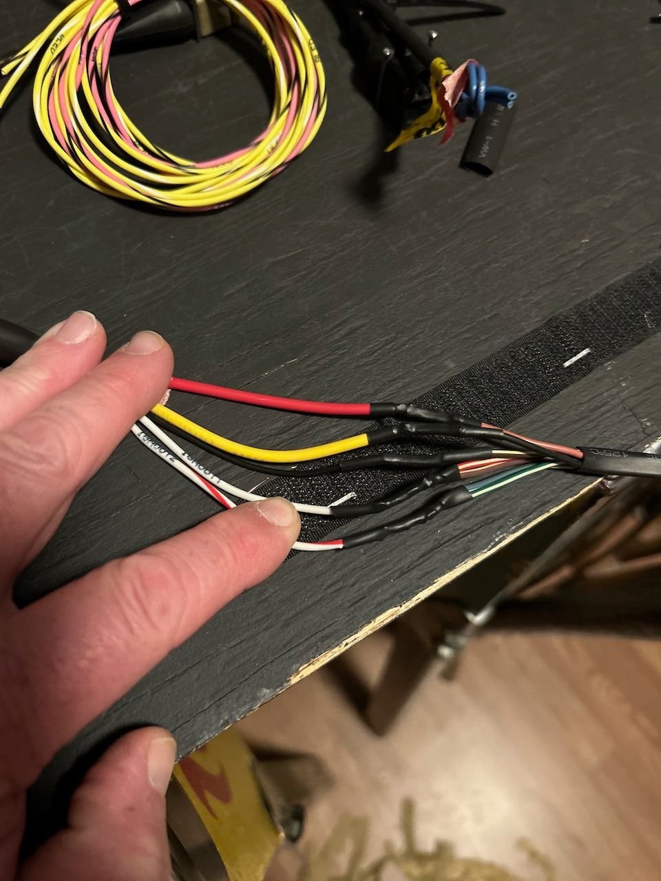
Just saw your latest videos. Before you get much further with the knock sensor wiring, I think you should strongly consider using shielded wire for the run between the sensor and whatever knock detection unit you use. This is how the factory did it, and its recommended in the documentation for the KnockSense unit. The key point is you want to keep as much external noise out of this circuit as possible, so as not to interfere with the sound signal coming from the block (which of course has its own sources of noise that the knock detector has to deal with). I used 20AWG 2 conductor mil-spec wire (M27500-20TG2T14) sourced from an aircraft supplier (https://www.aircraftspruce.com), but you can probably something suitable from a variety of places. I actually used this wire for all the important "high" frequency sensors in my harness--the crank position sensor, the speed and ref sensors, and a future cam position sensor.
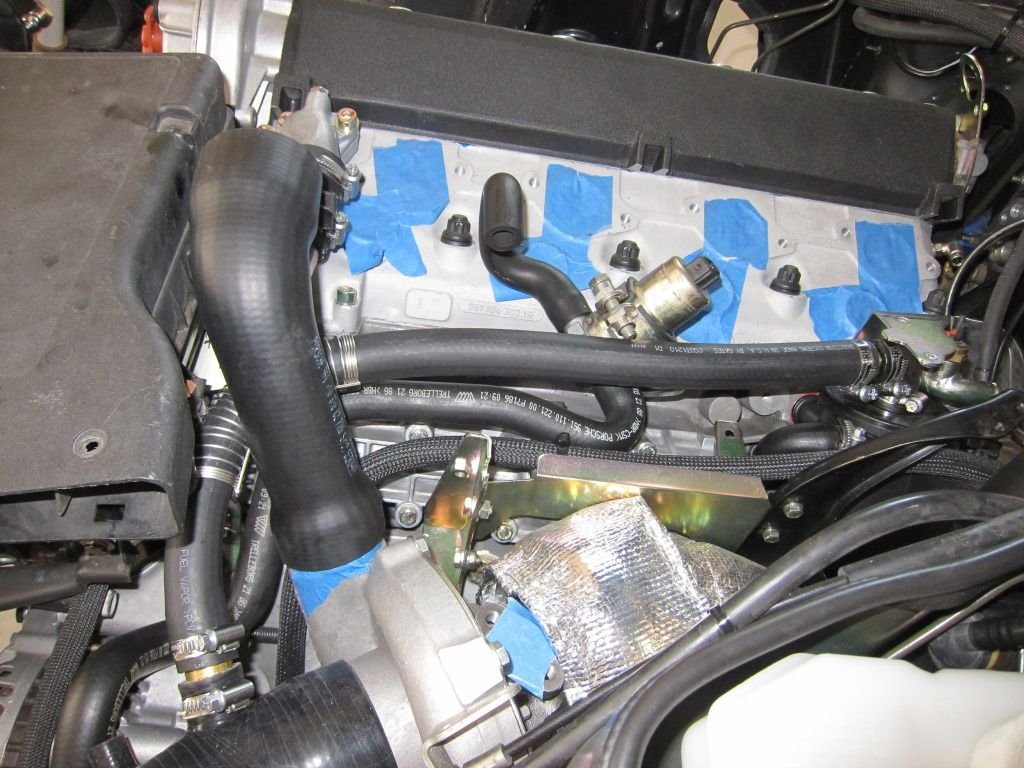
Regarding the ICV, if its a street car I expect you want to keep it. No reason to add another valve, as MS can drive the 944 valve no problem. If you haven't seen it already, take a look at my post on how to drive the stock 3-wire ICV from the FIDLE pin on the MS: https://rennlist.com/forums/924-931-...l#post15702597. This is essentially how the stock DME worked, although it used bipolar transistors. You can also go with a simpler circuit that just uses a resistor, however that will generate more heat. Incidentally, I have extras of the parts I used for this circuit [FET and diodes], which I could throw together on a proto board if you're interested.
Makes perfect sense. Did not put a new video out, but I have some shielded cable here so I re ran the knock sensor line with that, and I moved the f-idle output line over to the idle controller plug. Will check out your post again and reread. I had it in my head that MS would not run the stock idle air valve.
Great info I've had my new 3.0 running on mafturburner to get it running. I have a MS pro ultimate waiting to go in, all you're hard work and input from the group should help so much!!!
Thanks
Jay mentioned seeing two of them earlier, but today I have added three more videos to the Fifty-50 channel with test fitting of the harness and what now needs to be updated.
I'll be looking to you and all the others that contribute. Once I decide to go for it, I will send if it's easier to dump all my LINDSEY harness or pull it for some one that has a burnt up old harness. I have a spec lightweight flywheel with one trigger MS says is experimental in the MS manual. I'm sure I'll need to get a better trigger setup.
Finally got a chance to review the latest videos. A few thoughts:
- You definitely want the GSF wheel or something similar. I can attest that this will fit under the belt covers with only minor clearancing. Address I have for GSF is Albert Liang <albert@goingsuperfast.com>. If you can't get ahold of him there appear to be other vendors in europe that offer similar wheels.
- How are you planning to mount the crank sensor?
- What gauge wires are you using for the ICV and injectors? Of all the non-power wires in the engine harness, I'm pretty sure these carry most current. Factory used 1mm, which is approx. 17AWG. I used 16AWG but I'd guess you could make due with 18.
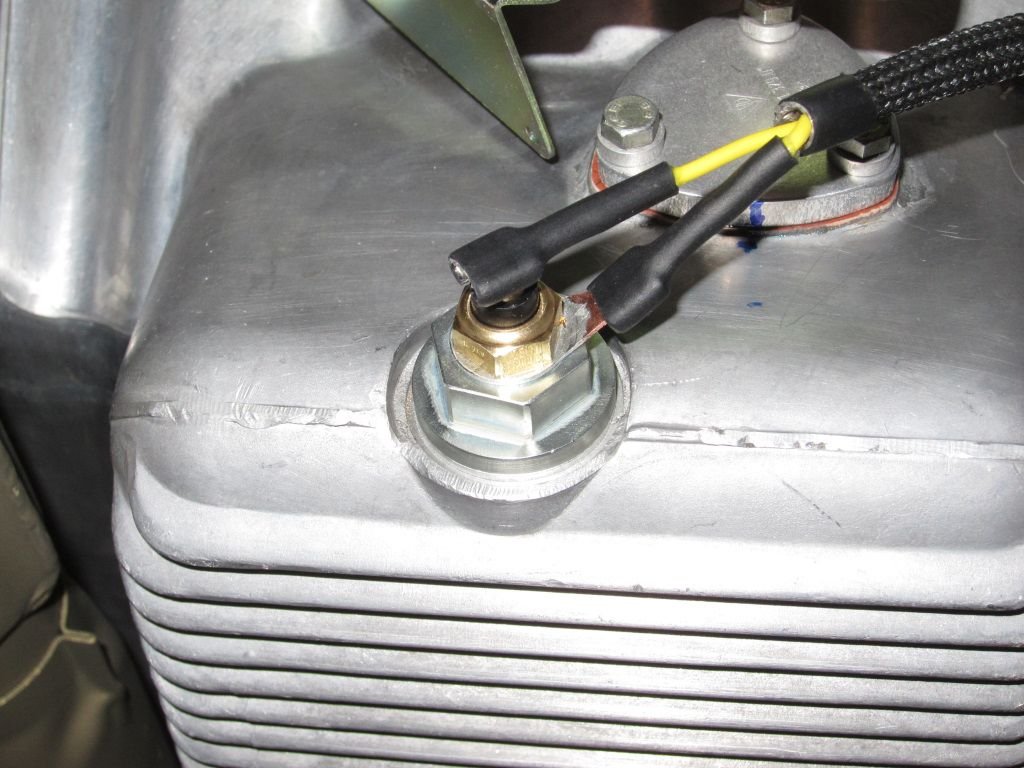
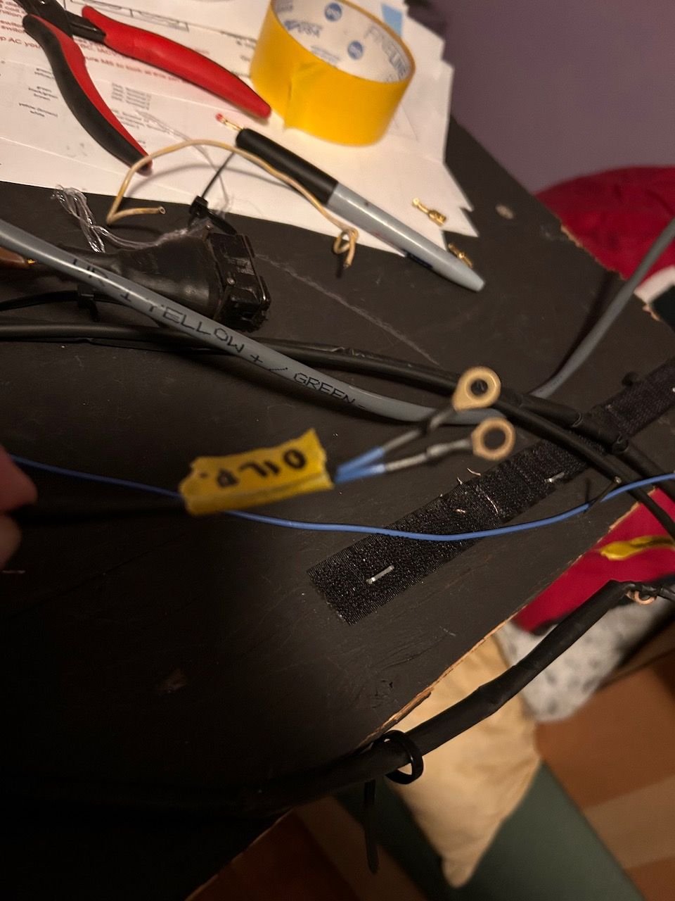
- Consider adding wires for an oil temp sensor in the drain plug (plug with tapped hole available from Linsday). I ran the wires along side oil pressure sensor wires, to the SpareADC1 input on the MS.
- You had wires labeled "MAF", but are you in fact running a speed-density configuration? If so, I think you want to place the intake air temp sensor in the hard pipe between the intercooler and throttle. This will better reflect the true air temperature (and therefore air density) that the engine sees.
- Regarding the wiring for the coils, will you be able to remove the wire harness without having to removing the fuel rail? Wasn't clear from the video, but I'd want to make sure that was possible.
- Also regarding the coils, any concern about heat with the coils mounted above the headers? Maybe it would be possible to fashion a heat shield that uses the same mounting points as the coil bracket?
- What's the plan for boost control? I ran wires for an AEM solenoid, which I drive via the MS ALED output.
- If you're so inclined, there are various write-ups that describe how to replace the hard pipes under the intake manifold. E.g. here's what I did for line from the AOS to the turbo inlet:
- Not sure if you've seen this, but in case its helpful, I have a spreadsheet with a detailed list of all the wires in the stock 86 951 engine harness, including colors and sizes: 1986-951-engine-harness-wire-list
RKT, your balance belt tensioner has been tightened in the wrong direction, it should be tensioned clockwise which will allow the idler to be adjusted with the correct clearance above and below.
RKT, your balance belt tensioner has been tightened in the wrong direction, it should be tensioned clockwise which will allow the idler to be adjusted with the correct clearance above and below.
Thanks , that was not final position of the tensioner idler. Still had final adjustments to do
The idler cannot meet the upper and lower clearance specs with the balance belt is in that position. The upper belt run moves down when the tensioner adjustment is rotated clockwise, the belt will then no longer hit the water pump pulley and can be supported by the idler.
You definitely want the GSF wheel or something similar. I can attest that this will fit under the belt covers with only minor clearancing. Address I have for GSF is Albert Liang <albert@goingsuperfast.com>. If you can't get ahold of him there appear to be other vendors in europe that offer similar wheels.
I have reached out to all three emails on their website but have gotten no response. Disappointing for sure!
- How are you planning to mount the crank sensor?
Custom bracket using mounts for PS and AC Compressor belt tensioners.
- What gauge wires are you using for the ICV and injectors? Of all the non-power wires in the engine harness, I'm pretty sure these carry most current. Factory used 1mm, which is approx. 17AWG. I used 16AWG but I'd guess you could make due with 18.
I believe I used 18 ga.
- Consider adding wires for an oil temp sensor in the drain plug (plug with tapped hole available from Linsday). I ran the wires along side oil pressure sensor wires, to the SpareADC1 input on the MS.
Had not thought of that but great idea!
- You had wires labeled "MAF", but are you in fact running a speed-density configuration? If so, I think you want to place the intake air temp sensor in the hard pipe between the intercooler and throttle. This will better reflect the true air temperature (and therefore air density) that the engine sees.
Yes I am deleting the Barn Door and going to use IAT and MAP (I guess that is what you are referring to as 'speed-density'?). I have seen some different posts about the true intake air temp and it makes sense to pull from the charge pipe.
- Regarding the wiring for the coils, will you be able to remove the wire harness without having to removing the fuel rail? Wasn't clear from the video, but I'd want to make sure that was possible.
Yes - the coil bracket has independent nuts to tighten it down above the fuel rail assembly, so I could pull if off if need be. In making that video I posted though it really looks like the plug will just slide under everything without moving it.
- Also regarding the coils, any concern about heat with the coils mounted above the headers? Maybe it would be possible to fashion a heat shield that uses the same mounting points as the coil bracket?
Wondered about that as well. Michael has his coils mounted to the inner fender and I have not seen him post any concerns, so I figured they would be fine.
- What's the plan for boost control? I ran wires for an AEM solenoid, which I drive via the MS ALED output.
MAC Controller but I am glad you reminded me to run the 12V line from the aux fuse box and move the ALED output wire over to that area. Planning to mount the MAC box to the firewall.
- If you're so inclined, there are various write-ups that describe how to replace the hard pipes under the intake manifold. E.g. here's what I did for line from the AOS to the turbo inlet:
Will check those out. I thought the hard pipe might be more elegant. I bought the Vac hose kit with Venturi delete to use but have not put any of that on yet.
1. Added the 12v feed from the aux fuse box (which is quickly growing full) and the WLED output to the location along the firewall where I plan to mount the MAC Boost Solenoid.
To address the aux fuse box, I may combine some of the low power circuits together on a fuse - for instance, the injectors and coils may get their own fuse, but the Arduino, Wideband, and MAC boost control may be fed from a single fuse - much like the mirrors and clock are sometimes fed on the same circuit in factory wiring.
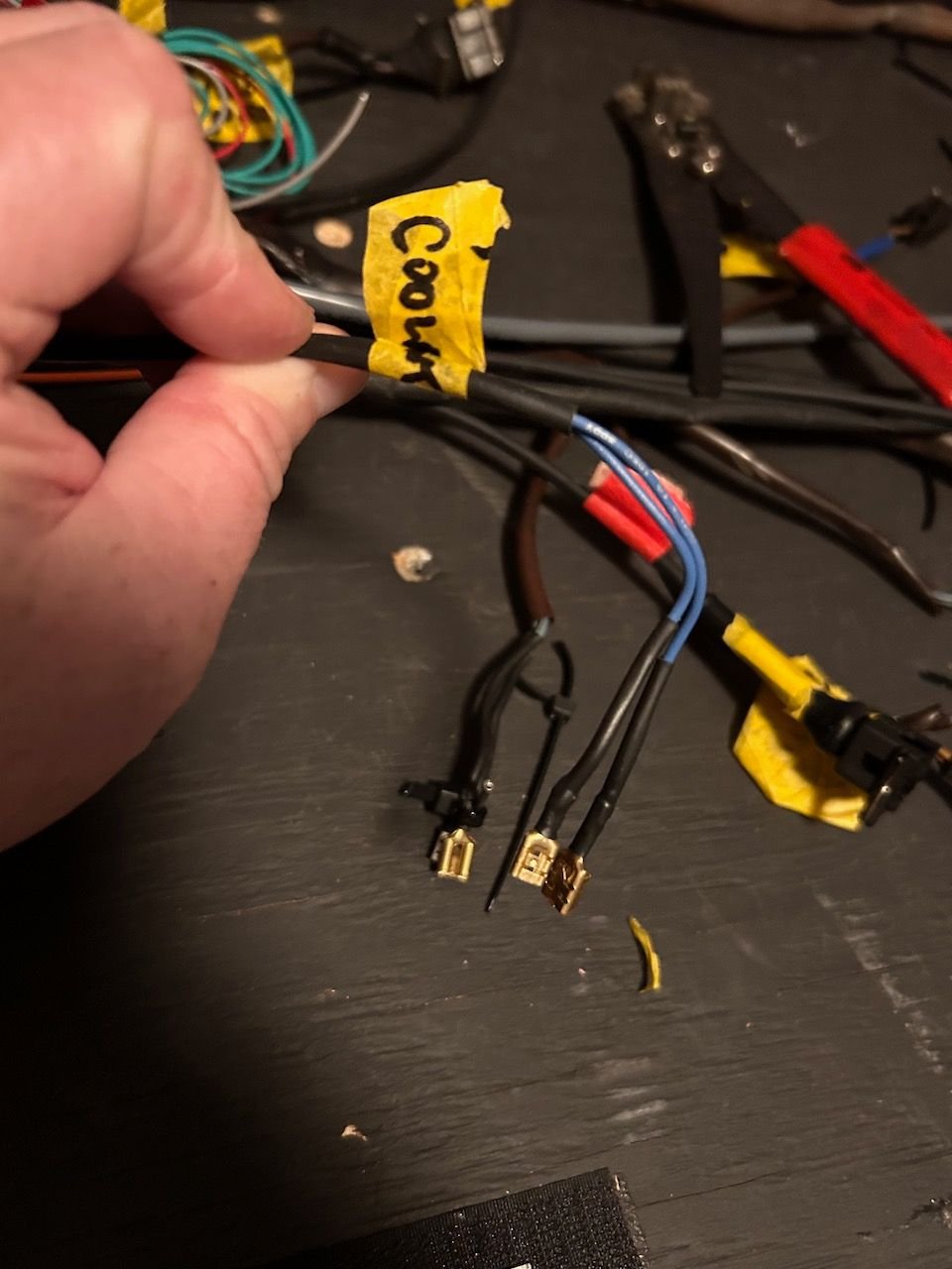
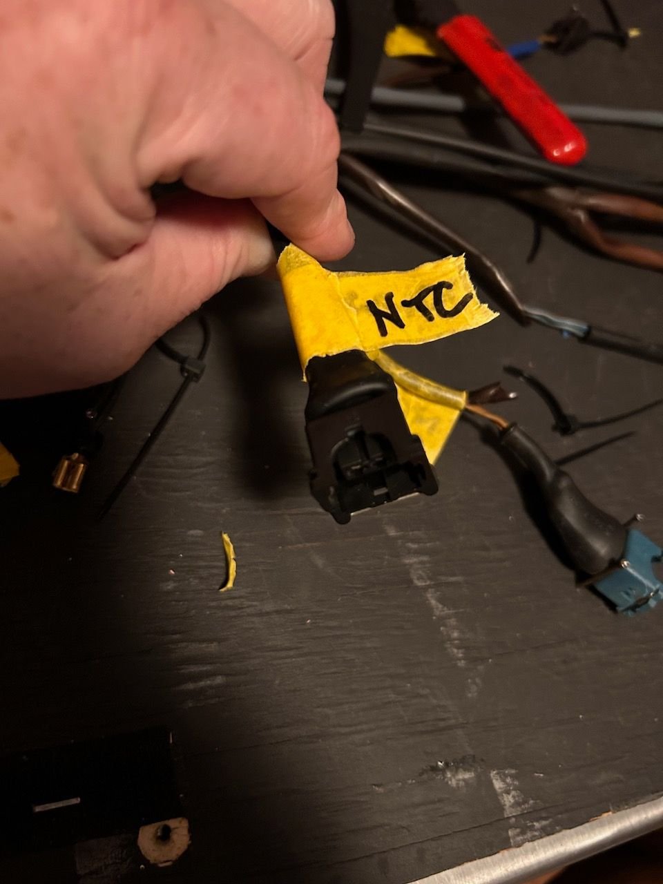
Wired in the coil harness plug and finished the sleeving. Added new connectors to the oil pressure sender wires. New connectors for the Coolant temp Gauge and light sender. Installed the first of many Jr. Timer-style connectors for the NTC coolant sensor.

 12-01-2022, 01:41 PM


 Glad to see it's been of some use.