When you click on links to various merchants on this site and make a purchase, this can result in this site earning a commission. Affiliate programs and affiliations include, but are not limited to, the eBay Partner Network.
Thanks - that is interesting regarding the AC. I thought the signals were simultaneous. That will need some think through. Is the blip so much that it causes a stall at idle?
as far as clewett - yes that is awesome, but I am unfortunately on a pretty tight budget just trying to get the car back on the road.
do you think I will have any trouble with the 6 3/4� wheel like I have mocked up? I think that a wheel is a wheel for what I am doing - and I really don�t want to damage anything from the factory in case someone in the future wanted to go back to stock (eg cutting into the belt covers or wiring harness).
Re-AC, there�s enough latency that you will always get some amount of a a dip unless you can control the idle calibrations preemptively. Definitely nowhere hear stalling as along as your have your base idle calibrations dialed in well though.
I couldn�t speak to the wheel size you�re proposing as I have no experience designing a trigger wheel. I think it�s probably most important that you are able to cut the teeth accurately and use a profile as well as missing tooth section that works with your sensor type (hall vs VR). Additionally that you can adjust your gap as required, it sounds like from your video that you have that consideration under control with your bracket design though. As far as sensor, VR requires more calibration during setup but is a more reliable sensor and allows higher teeth counts for better engine speed signal accuracy, so I�d suggest going that route. However hall will work completely fine, just personal preference.
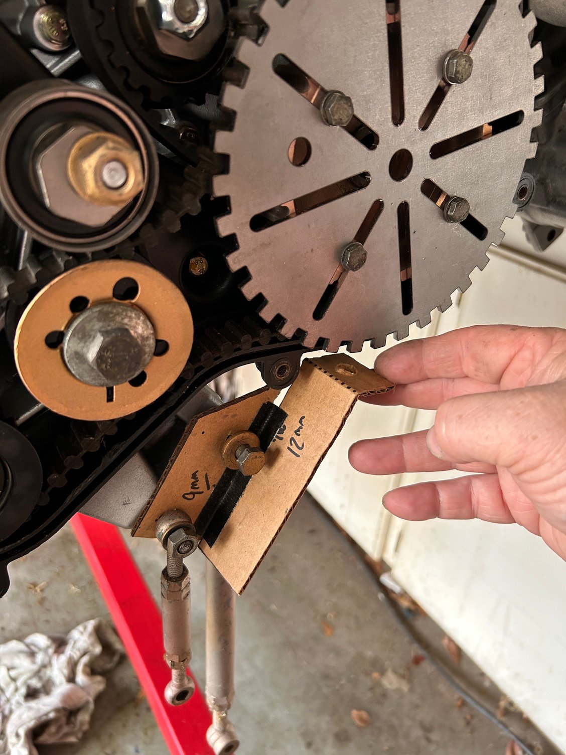
Sorry I misled you. I already have a wheel from DIY Autotune. I just made a mock-up out of cardboard before I started cutting the good wheel. It�s a 36-1 setup. Here�s a pic.
I wish I had the stuff to make things like this!!
I will have to cut the middle out of the wheel to sandwich between the two factory pulleys.
that was the original bracket I was going to fab up but I have a sensor with two screw mount hea instead of threaded fitting.
Porsche already built you a 60-2 tooth trigger wheel it's on the S-2 and uses the same clutch setup as the NA I am using it to run a 88 turbo motor I swapped in a 86 NA
I went the quicker route with my harness I used a S-2 harness
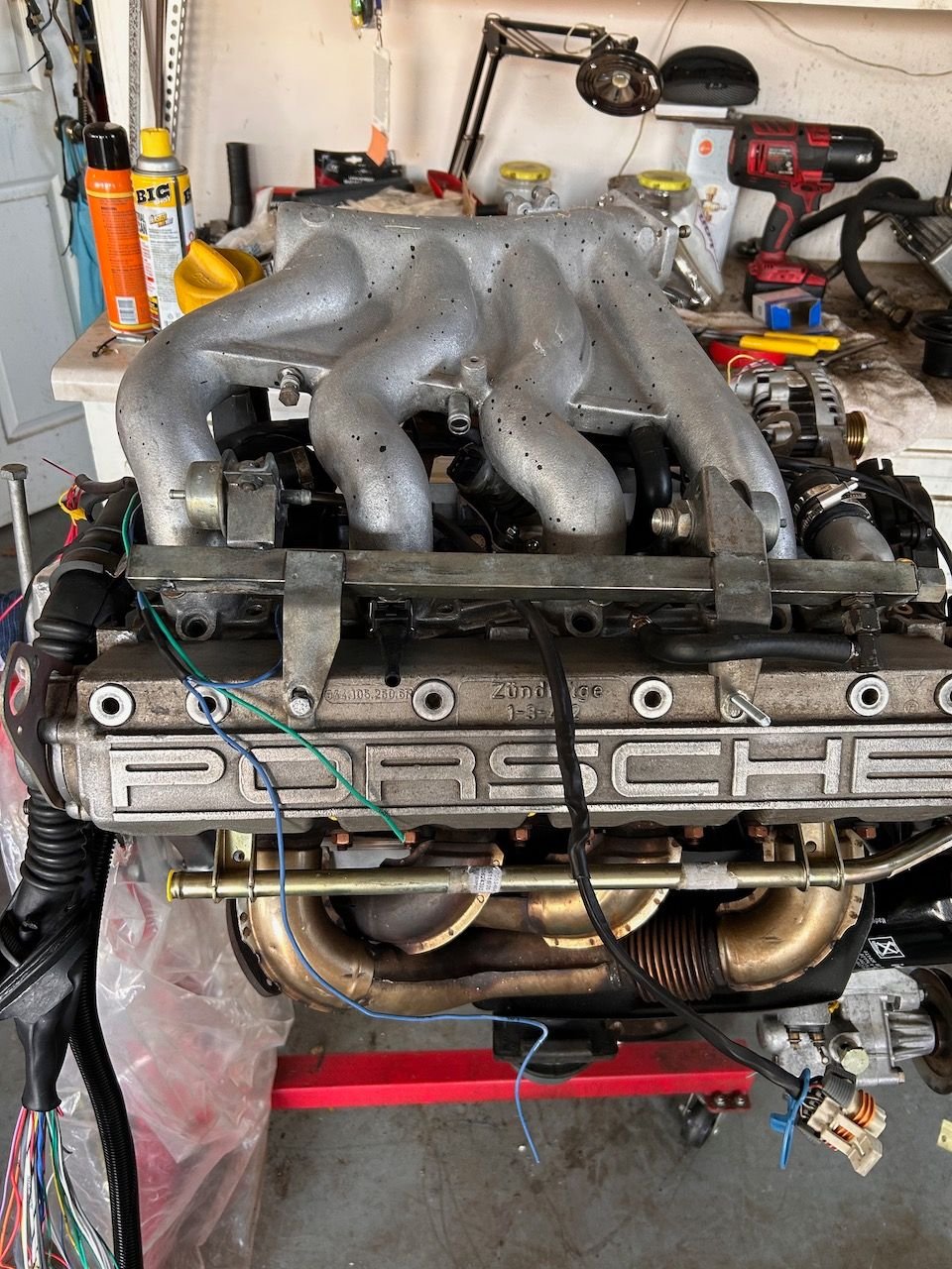
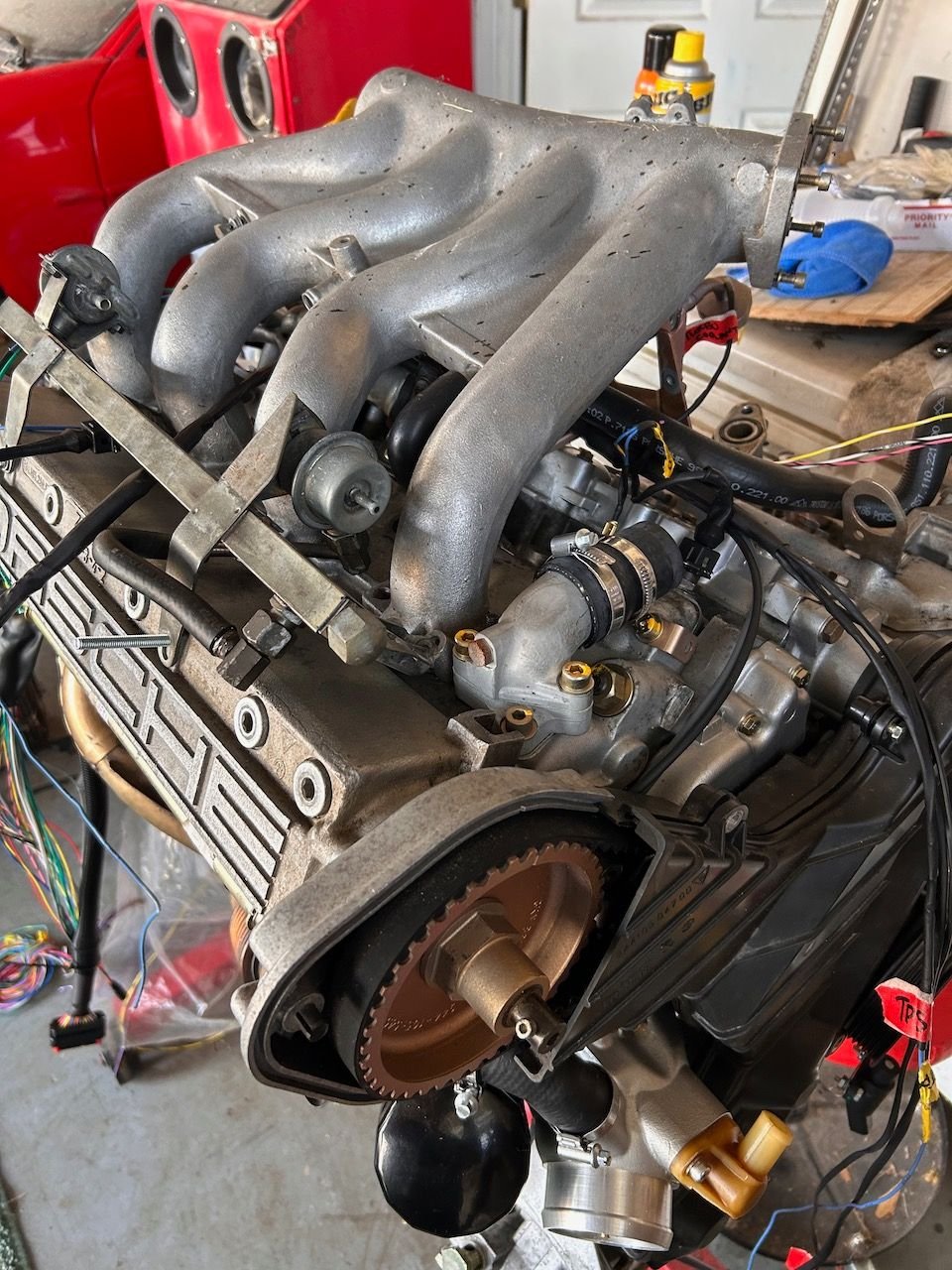
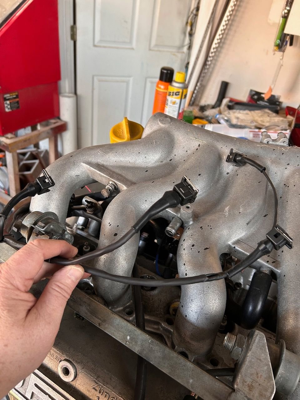
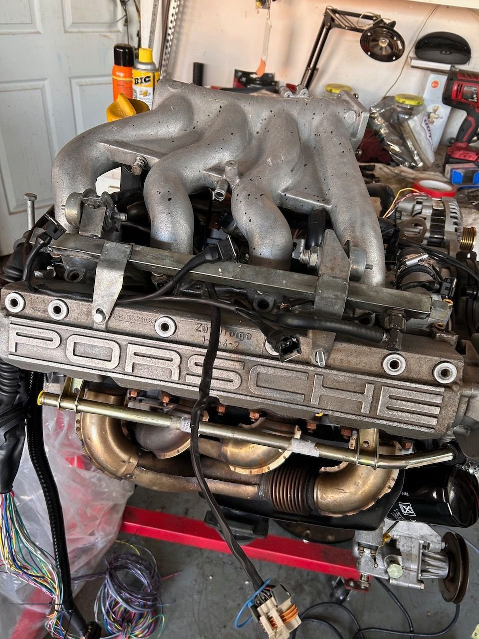
Pretty productive weekend at the Fifty-50 Garage. Here are some pics. In short, the fuel injector leg of the new wiring harness was readjusted once on the engine (some legs too long, etc.). Easier to sort that out once I had things together a bit more to look at lengths and paths, etc. Also recovered that section with shrink tubing afterwards and installed connectors.
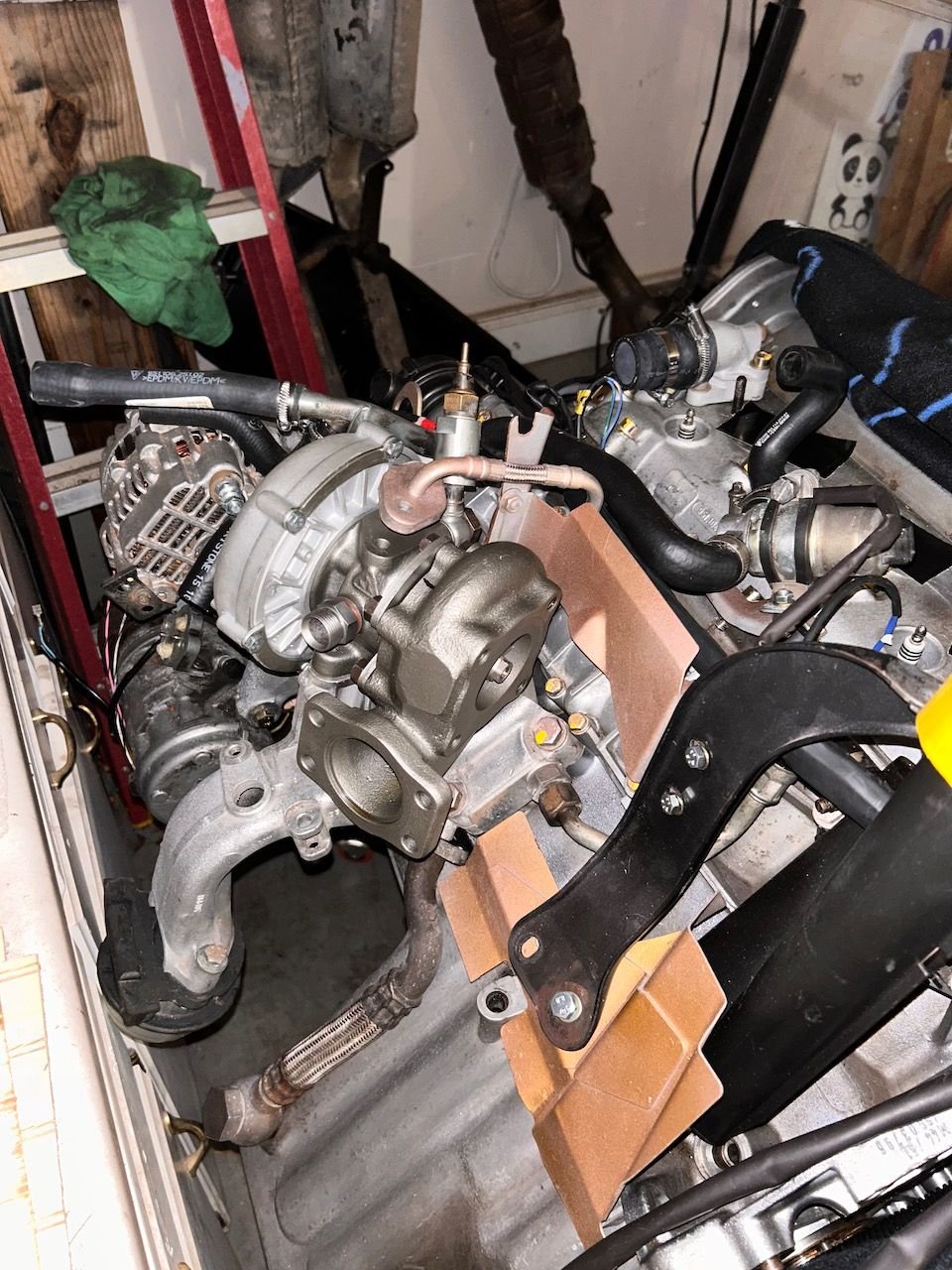
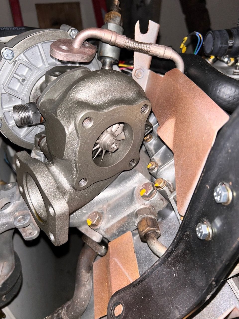
Also got the turbo mounted. Cannot stress enough to those doing turbo work in the future to MARK the turbo (my rebuilder called it 'indexing') before disassembly. Now that I understand how it comes apart I see what he means. Simple explanation - use a punch and put an alignment mark on the turbine cover housing, the impeller cover housing, and on each side of the center cartridge section so you can get that exactly right on reassembly. I have had to put mine on and take off several times as points where feed pipes, etc. attach via hard lines do not line up and obviously cannot be slightly bent to fit. The alignment has to be perfect.
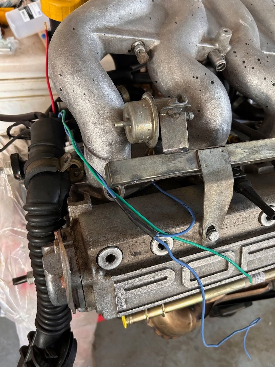
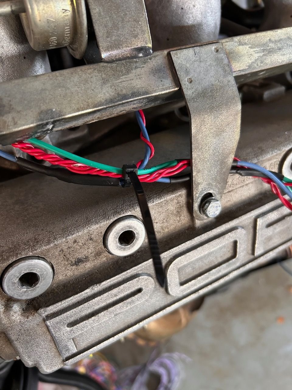
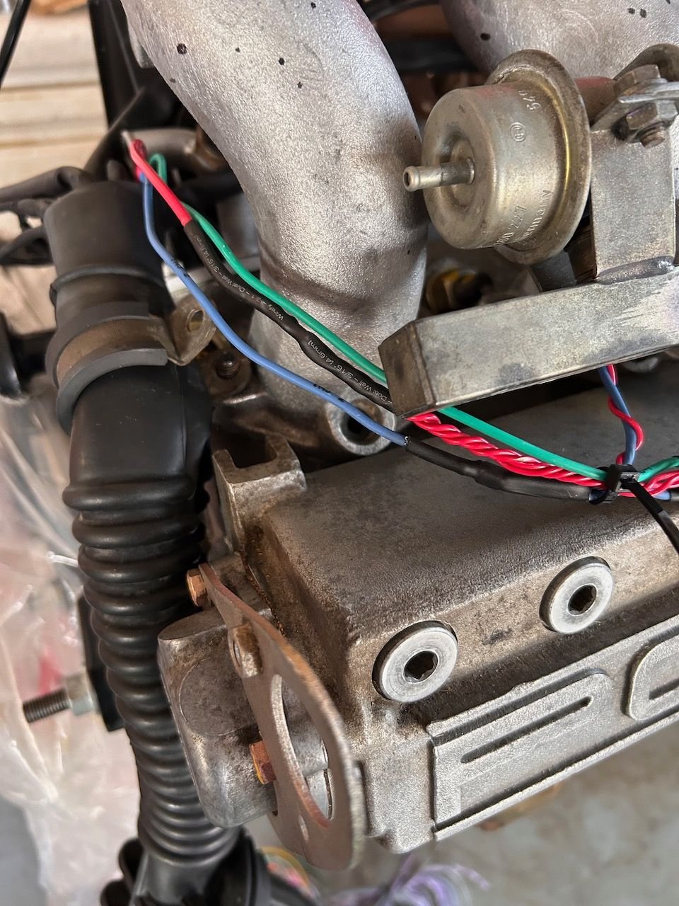
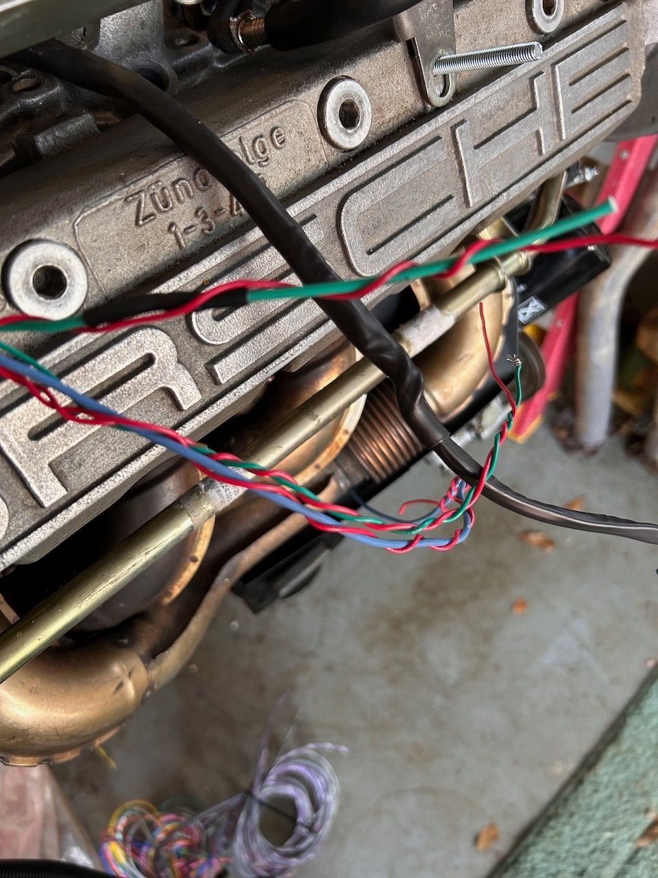
Test fit the intake back on to figure out the pathways for the FI wiring. Remember on the factory harness there is a plastic cover on the fuel rail that hides the harness. Looks good with the intake back on. Look at all of the room under there with the snake of tubing gone! Pulled harness back apart to rework it. The green and blue are the (-) triggers from the MS. The red will be the +12v from the new fuse box. First break off point for injector 4 Twisted the +12v feeds for strength. The black wire underneath here is the coil pack drive. All finished - with new shrink tube and connectors mounted. Money shot. Turbo mounted in place. Note the oil feed line not connected. Turbo will have to come off again as this is alignment is still not right. Closer shot. That feed line looks like it will just flex right into place but not so...
Got the turbo feed line connected. Did not have to take the housings loose again - just loosened the banjo on the balance shaft cover end and was able to get everything lined up. Check that off the list!
Last of the connectors should come in this week and I can wrap up the harness project.
I will have to cut the middle out of the wheel to sandwich between the two factory pulleys.
I gather that this approach involves using longer bolts to attach the trigger wheel and accessory pulley to the balance belt pulley. So is your plan to use hollow stand-offs between the back side of the toothed wheel and the shoulder inside the accessory belt pulley?
I would think you need to to properly hold the accessory pulley against balance belt pulley.
Thinking about the positioning of the new bolts, it seems like the stack up of the trigger wheel plus the bolt heads, plus maybe a washer, is going to interfere with the position of the power steering pulley. If the interference is small enough, you could perhaps stack a washer under the ps pulley to gain more space.
The downside to this is it will move the ps pulley out of alignment with pulley on the ps pump. In theory this could result in some increased noise and/or belt wear. I'd have to think about whether you could adjust the positioning of the ps pump pulley.
I wish I had the stuff to make things like this!!
You know, the design of these wheels is so simple that it shouldn't be that hard to develop a CAD model that could be easily produced by an online metal fab. In fact, the design is so regular, I'd be inclined to create the model programmatically using a script-based parametric modelling language like OpenSCAD or CadQuery. This looks close: Gear generation code with openSCAD
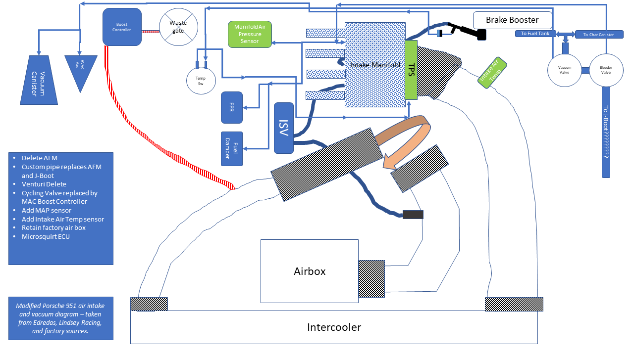
Trying to determine the conglomeration of what I need in terms of vacuum and airflow for the new motor. Please take a look at this poorly-drawn diagram and tell me what I might be missing. Notes are on the diagram as to the scope of the project. Lots of things being deleted and added at once so complicated.
Credit to Edredas, Lindsey Racing, and the factory for the diagrams, videos etc that this is adapted from.
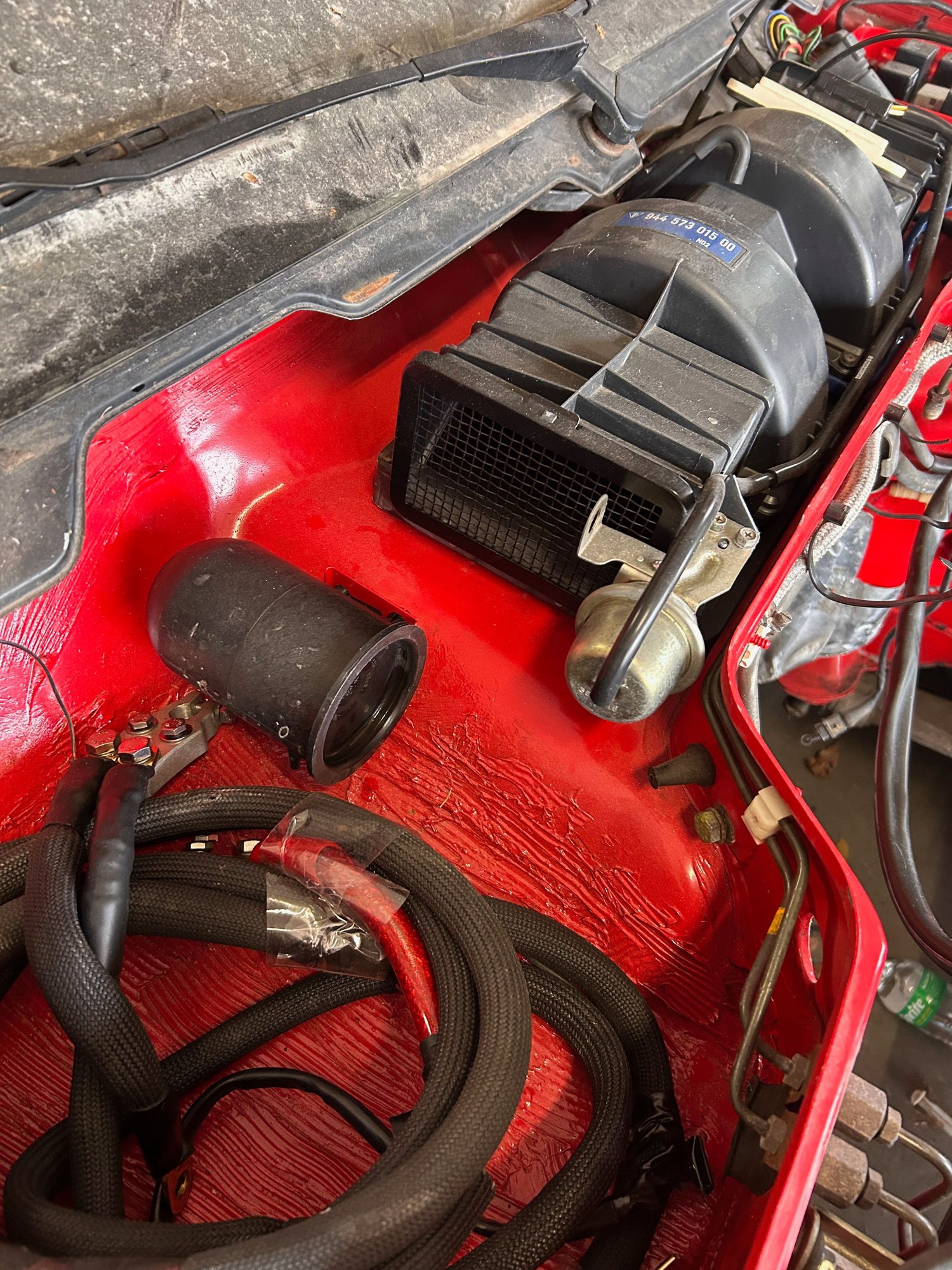
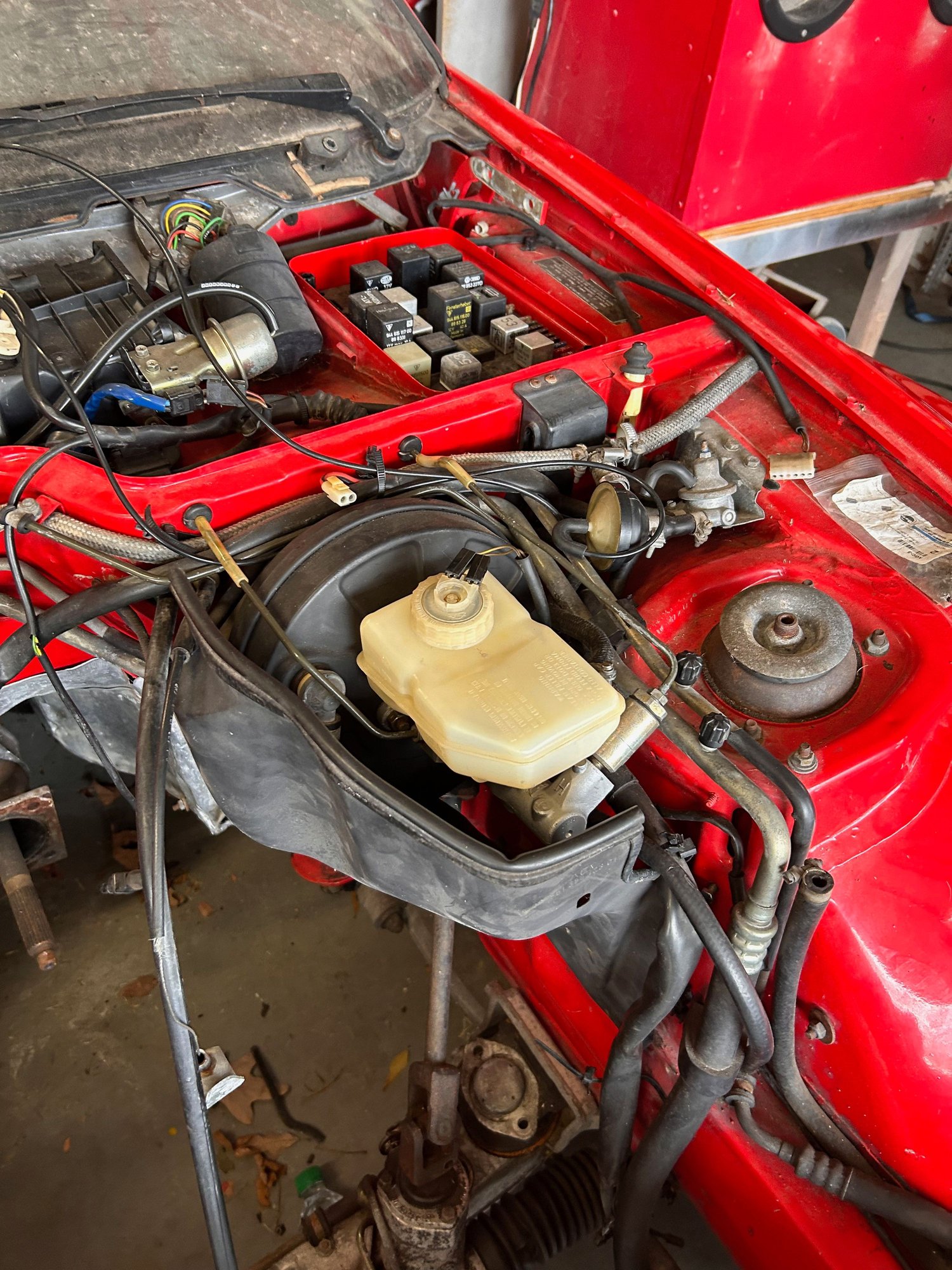
Here are a few updates from the first part of the weekend. Good progress!
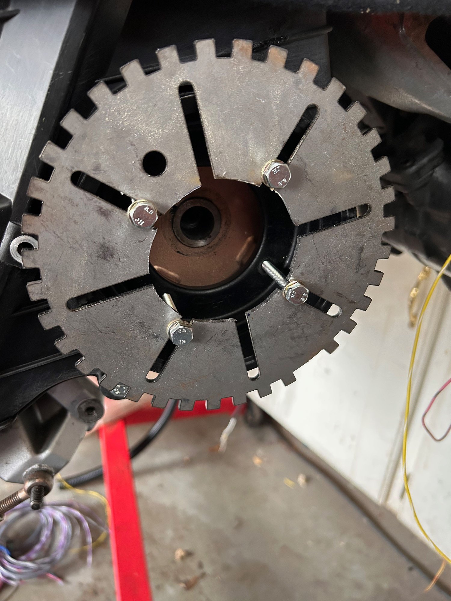
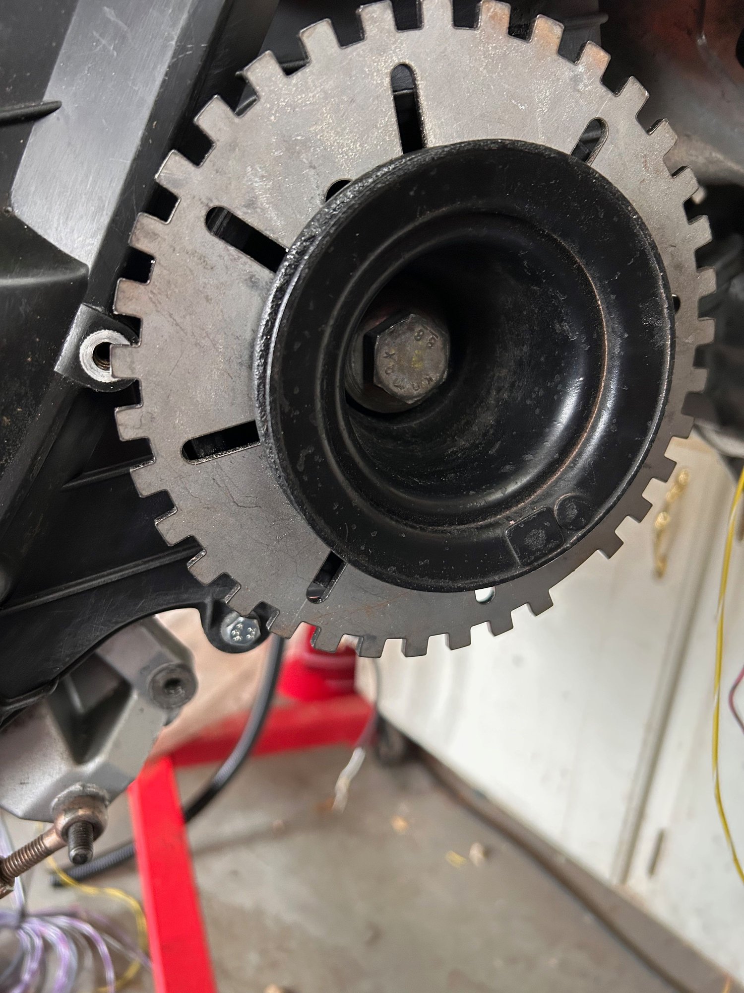
Got the vacuum reservoir back in place. This is important as I have to work out mounting of aux fuse box (new) and new MAC Boost Controller. Got the Master cylinder and reservoir seated and the heat shield temporarily mounted. Not putting it down tight yet in case something needs to shimmy when the motor goes in. Got the hole cut in the center of the new trigger wheel. You can see my initial idea to mount using a simple longer M6, but I think I am taking the suggestion to use a threaded extension that will allow me to tighten the pulley and trigger wheel independently. Here is what it looks like with the PS pulley mounted. Have to check the centering of the trigger wheel but it is a pretty snug fit to the back of the PS pulley.
For what it's worth, I sandwiched the trigger wheel behind the main alternator/AC belt pulley on my '83. Yes, it puts the belt out of alignment by 3mm or something. But it has been 7.5 years and no real-world issues.
That is good to know. I'll measure mine as well - I need to go get a new alt and PS belt to check them out.
Do you think the diagram I made for the vac and intake lines looks feasible? I just want to make sure I have everything covered since I am doing a lot at once (Venturi delete, cycling valve delete, MS, etc.). Also need to verify the placement of my IAT sensor (right next to the TPS sensor in the new tube). Boost controller 'source' air is also a question: is taking it from the same location as the factory source from the charge pipe the best option? I know the factory setup has three lines going to the cycling valve but the new boost controller only has two.
Some work from today:
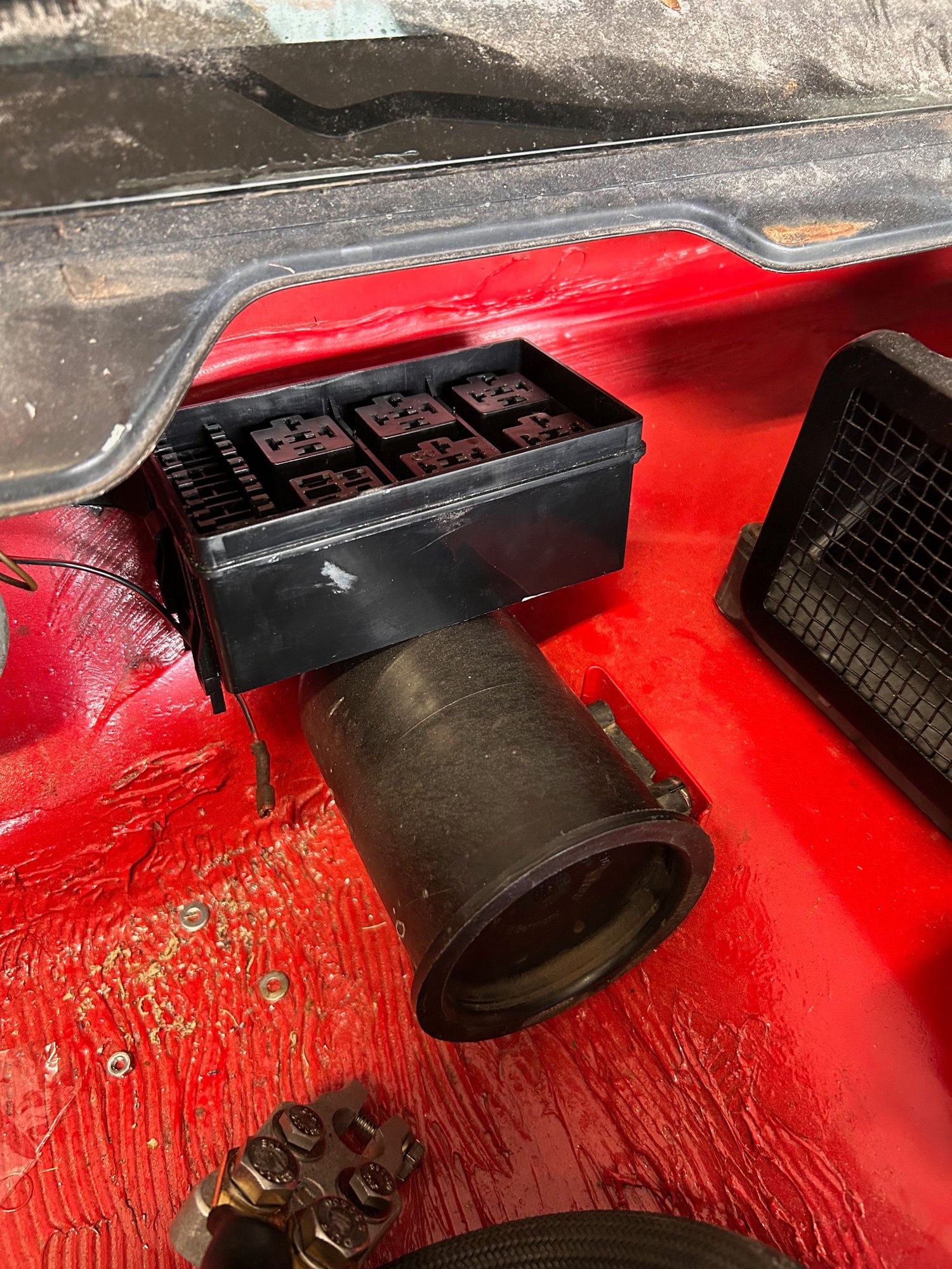
Got the placement for the new aux fusebox in place. Planning two relays here, both triggered from the DME relay in the main fuse box. There will be two relays in the box - one to feed the new cooling fan PWM controller, and one to feed everything else for the MS system (coils, injectors, Wideband, Arduino, knock box detector, ISV, etc.)
Each one of these will be a separate fused circuit, with the fuses in this box as well. Close to battery and all wires included in the new harness.
Got the new TPS connector wired in for the new harness. Would have done the ISV as well, but the connectors I ordered did not come with boots (ugh!).
Most of this weekends work was on cleaning the exhaust components (see other thread on exhaust sealing rings).
Did a few things though on the front side.
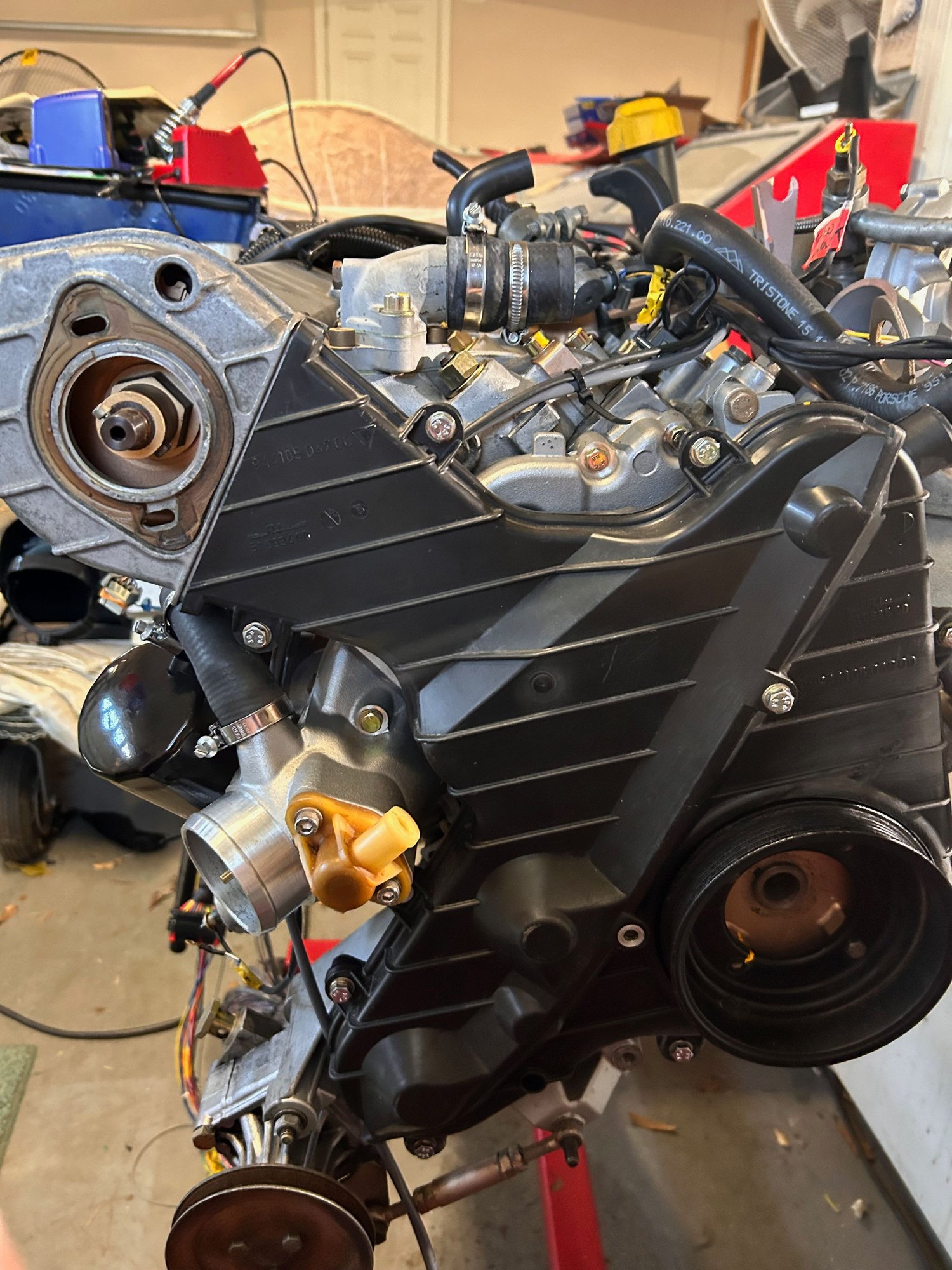
Got the ISV valve connector done. This will have a little electronic wizardry inside the car to allow correct operation. Most of the time today was spent getting front belt area tightened up (literally). Got the timing belt on and tightened. Also got the balance shaft belt on and all tightened up. Rotated the engine and everything seems in order (actually did it multiple times as I went through all the processes. All seems well. Will post a video of that soon.
I took the trigger wheel back off to worry about the front belts. Still waiting on the mounting bracket for the sensor anyway, so no worries. Easy to pop the PS pulley off and get the trigger wheel in place.
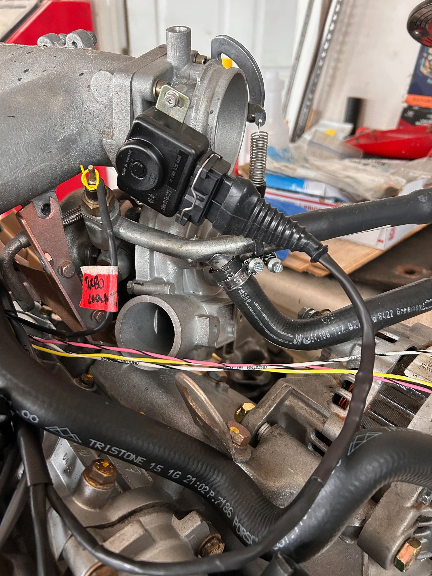
Most wiring on top of engine is done. Still have to add connectors for MAP sensor, turbo coolant temp sensor, trigger wheel sensor, and intake air temp sensors. Cannot do most of that until I have my intake tube from air box to turbo fresh air inlet so I know exact location of sensors. Still have some vacuum plumbing to do as well.
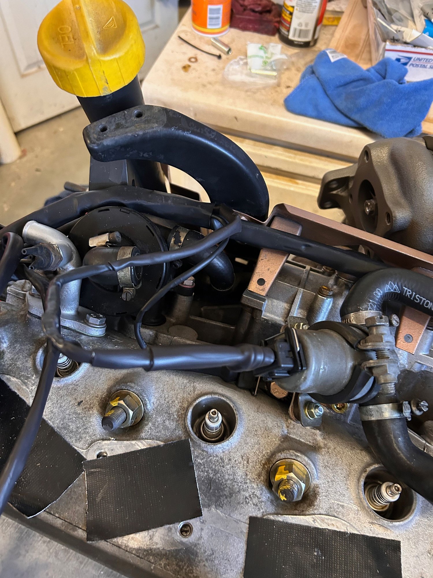
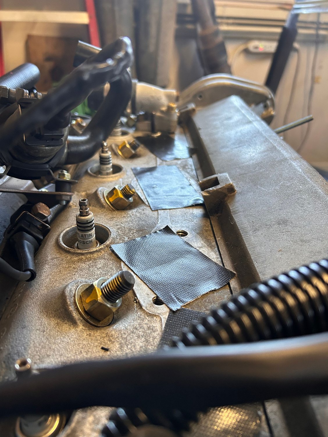
That is a great question gage. They are not all like that. I asked a couple of folks who said that amount of variance was not a concern as long as everything torqued down as it should. It seemed too, so I have not worried about it. What are your thoughts? Here is a pic across the top so you can see�


 12-31-2022, 02:43 PM