Rough Life Wilson - Thread con't
#47
Race Car
Thread Starter
the 951 oil drain is below the oil level to sort of insulate the draining oil from crankcase pressure.
the 928 guys have a whole nother level of oil problems, the theory is that crank pressure sort of fights the oil draining down from the heads and backs it up the return chutes.
if you look at newer stuff like the 5.0 Coyote they actually built "vapor chimneys" on the valley side to let crank pressure go to the heads and equalize pressure for better draining/PCV function.
plenty of cars drain to valve covers though so it must "work".
1) draining oil shouldn't have to compete with the sump oil "head pressure".
2) draining too close to the oil pickup tube allows hot turbo oil with aeration to be sucked up into the engine.
This is why I went so high on the pan, to allow me de-aeration and cooling for the return oil.
I just wish I positioned it farther away because I didn't give the drain line much room!
#48
Race Car
Thread Starter

WOOHOO! Baby step, I know. but god dammit I'm now at the stage where I put power & ground to the ecm. Next step is to read the magnets, orientate their polarity. drill out the old ones & install the new ones properly (its a pain in the ***, but the most critical element)…
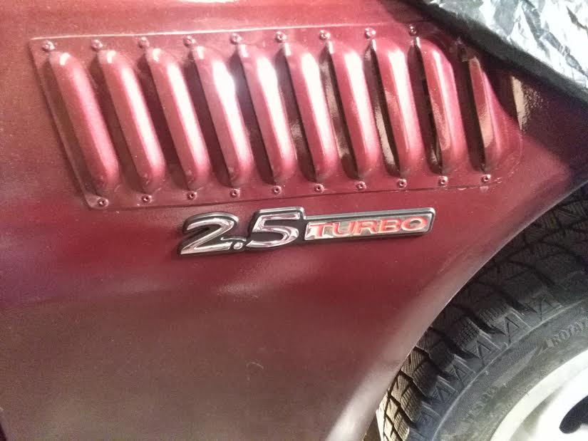
So to celebrate, Wilson the magnificent got awarded some Emblems today

#49
Race Car
Thread Starter
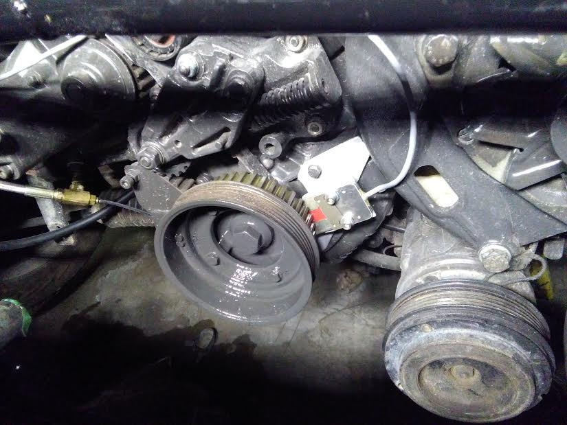
Another score last night. Front pulley mounted and I measured the minimum required distance between the magnets & the hall sensor (1mm).
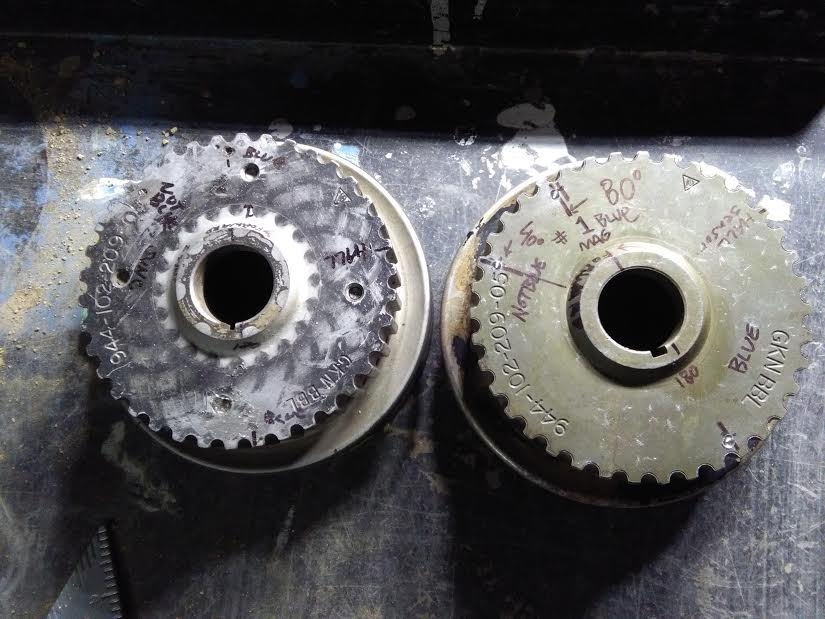
Special thanks to Bob from Cochrane, Alberta for his huge donation of 944 parts 2 years ago. Having another crank pulley in the parts bin came in handy. The first attempt to mount the magnets resulted in them being seated too low. Yesterday I tried to drill out a magnet...YEAH RIGHT, GOOD LUCK WITH DAT HOMEY

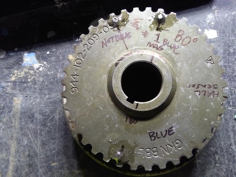
New magnets installed. 2 magnets with polarity in same direction get recognized by the hall sensor (I still need to verify on the ECM programmer screen that it reads "Magnet Seen" twice and "Sync Seen" once). But my next priority is to ensure engine cranking and oil pressure. The ecm fires spark plugs based on seeing the magnets.
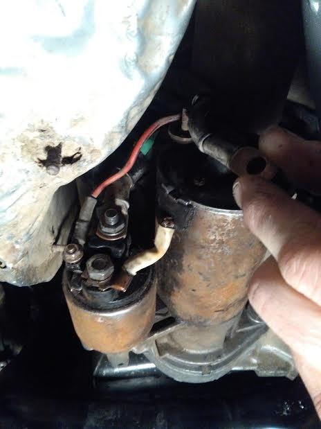
Please help. Haynes manual doesn't say. I forget... where does this negative cable go? Seriously I dunno.
#50
Rainman
Rennlist Member
Rennlist Member
the theory above certainly is interesting, don't imagine sucking up 250* oil out of the turbo is very useful for pressure

and to answer your filter question, the nipple at the center is the "return" chute into the block.
the "circumference" holes around the nipple come from the pump.
flow through the filter is from the outside, in.
#51
Race Car
Thread Starter
That's great to hear brother! I wish you success and a smart guy like you will have success no doubt!
Are you going to start a new thread for your SC 944?
-----
Thanks for the filter info.
-Still wondering where the big ground cable near the starter goes.
ALSO:
-I removed the spark plugs to reduce load & wear. I'm cranking and have no oil pressure.
WHAT should oil pressure be while cranking?
Wilson always fired up in a milli-second right to 5 bar, so this is new for me.
I want to pre lube engine and ensure the pick up isn't broken. I heard a "crunch" when I was installing the pan and I am hoping it wasn't my pickup tube.
#52
Rainman
Rennlist Member
Rennlist Member
trick i've used to pre-oil an engine that's sat...
come up with fittings to screw in place of the oil pressure sender (M18x1.5 thread to male hose barb for a 944)
go get a hand-operated fluid transfer pump (auto stores should have it for $15 or so).
put the suction hose into the bottom of a jug of oil and the discharge hose clamped onto the hose barb fitting above.
start pumping...you'll force oil at some PSI up through all the galleries. i did this on both my subarus this year after +/- 1 month repair periods and was able to force over a QT of oil into each one by hand.
when ready to run, pull the plugs, crank it and build pressure...then install the plugs without the coil wire, crank it some more, then hook it up and it should fire up quietly.
#54
Race Car
Thread Starter
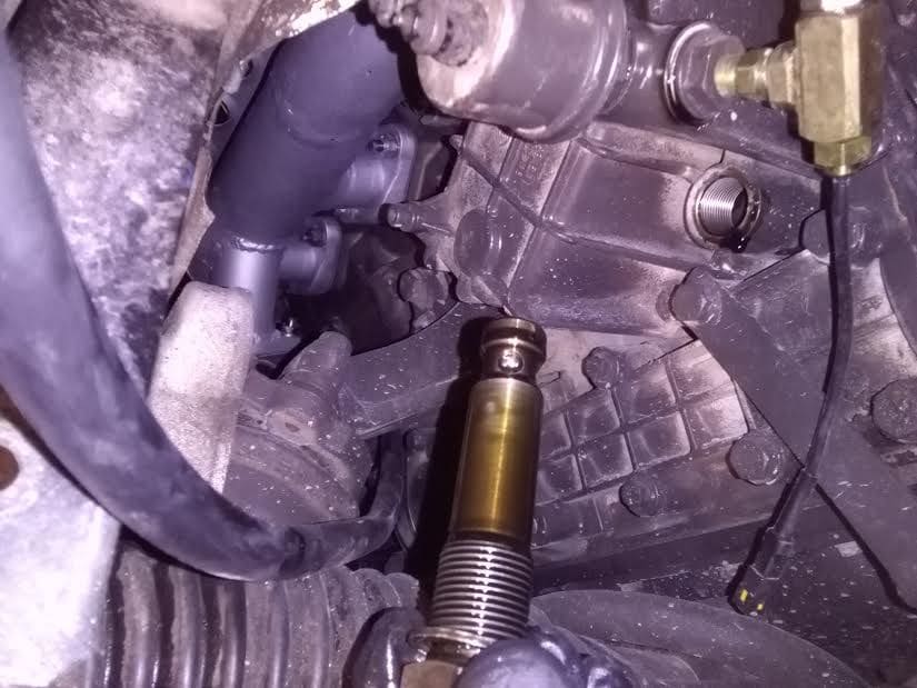
Darn it! So close yet so far, I was shooting oil in the wrong hole!
Correcting my mistakes, removed Oil Pressure Valve.
Looked in the hole & it's a 3" upward trajectory.
BOOM! Hitting them outta the ball park today Son!! Verified this post is for the oil pressure gauge. It's the blue & white wire that goes to the connector near the brake booster then to the gauge. As long as the block is grounded, it'll work with key on. Tested the pressure sender and gauge by removing sender & shooting 25 psi of air in the
hole of the sender.
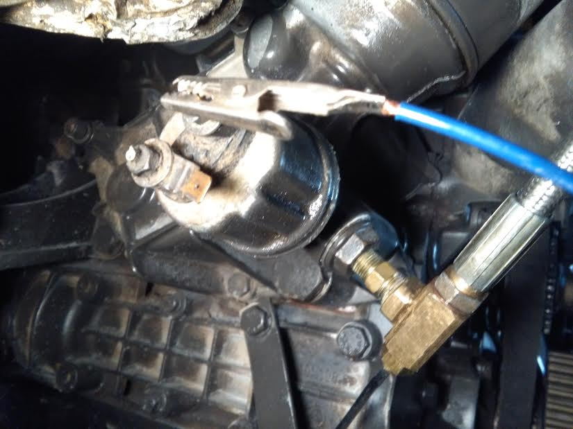
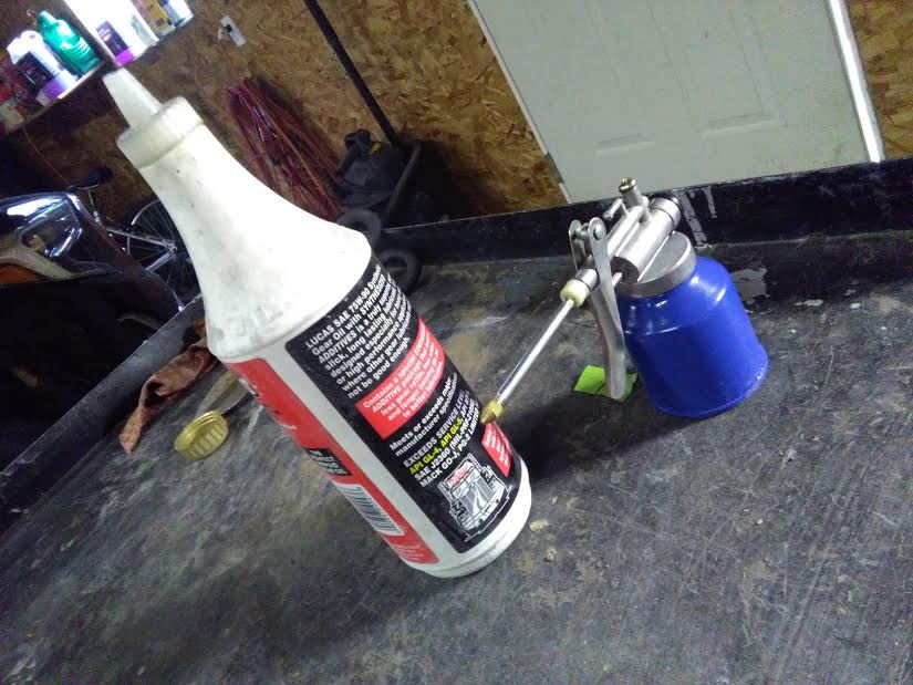
Below: Looking at my immediate resources, I could use one of these. The little squirt bottle worked really good. Used 4 tines of oil. Cranked. Within 10 secs I was up to 5bar OIL PRESSURE! That's just cranking. Yay! I'm so high I could kiss the sky

Above: by the way in the brass T Fitting, you might have noticed the sensor. It'll (down the road) tell me oil temperature. It came with my digital motorcycle dash.
#55
Rennlist Member
Michael, if you are reading this, the diagram you sent me (with the red and black wire, possibly pin 7 is labelled "ign switch", is this for the starter solenoid? or just a "switch 12v source") … The term "ignition" can be confusing because it has so many applications. Thanks.
#56
Race Car
Thread Starter
Okay, that makes sense. Thanks for replying.
This whole electronics to electrical conversion is interesting to me.
I generally really enjoy and typically do fairly well (at work as a mechanic)… but I the wiring schematics in the Haynes manual confuses me to no end... so I'm just poking and prodding and using a lot of fused jumper cables to be safe.
#57
Race Car
Thread Starter
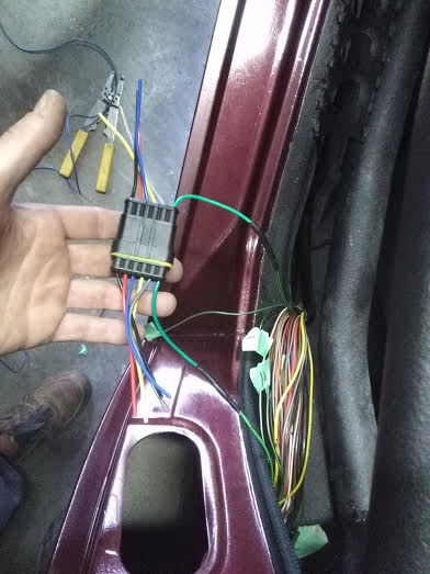
SDS EFI uses ground inputs to relays for fans, pumps, devices.
I have been trying to get the oem fuel pump to run by jumping battery power to the power (+) circuit. Once I hear the pump run, I can complete the SDS relay wiring (note: they designed the system to shut fuel pump off it the crankshaft isn't turning-seen my the hall sensor near the crank pulley.
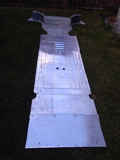
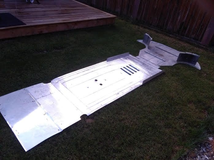
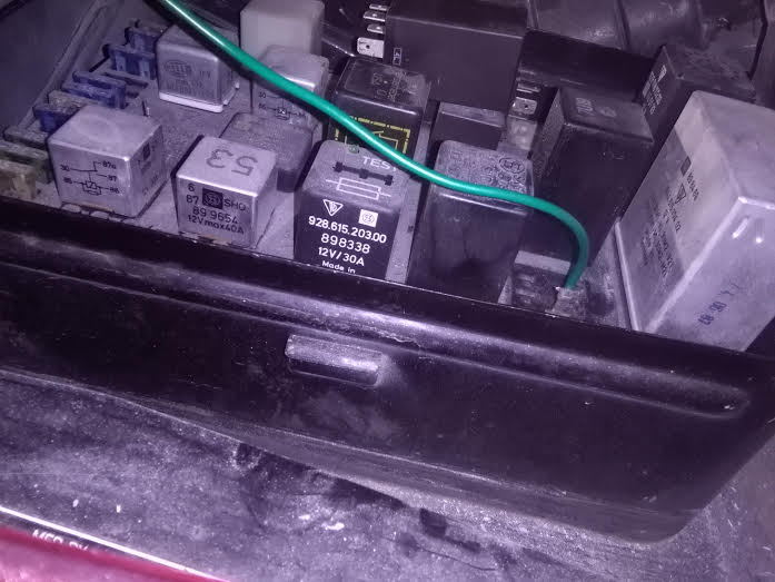
Short story long. The biggest green wire with black stripes near the driver's door is the power wire to the pump. I have always wished Porsche made a connector here. So I'm inserting one. The fuel pump gets ground from close to where the rear lic plate is. Silly me didn't have it hooked up after painting the interior. Now, with a proper ground I heard the fuel rail filled to capacity. This can be accomplished by feeding a 12v power source to either the fuel pump fuse or the DME relay circuit.
#59
Race Car
Thread Starter
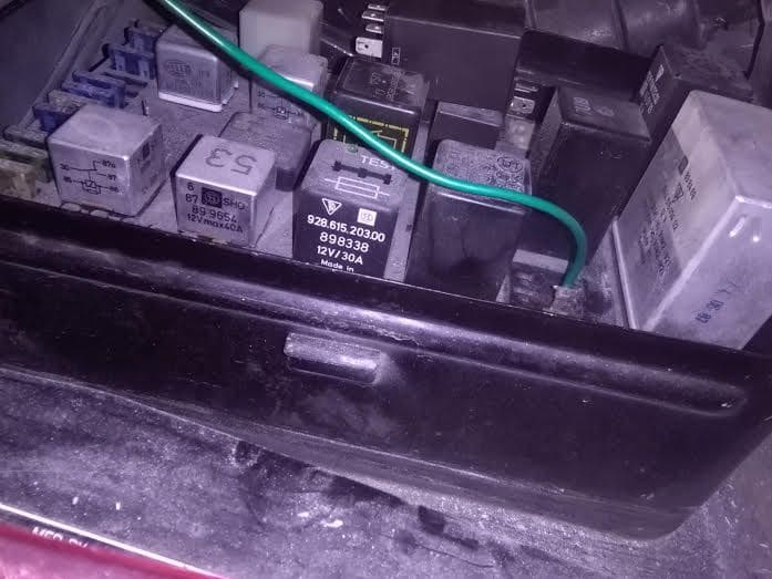
I tried to start my engine 2 days ago. It didn't start. I cannot smell gasoline from the exhaust, so I suspect the injectors aren't getting a ground from the ecm. Or maybe no positive... but I'm not going to persue this problem yet because I have to much chaos under the hood; like 55 wires with tape on them and then I have jumper wires with bare terminals... nothing properly secured. I need structure/organization in order to think straight and I also know exposed wires can lead to electric/electronic damage. So I'm going back to secure things and fabricate things & then install them properly. Then I double check my wiring & begin diagnosis.
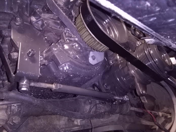
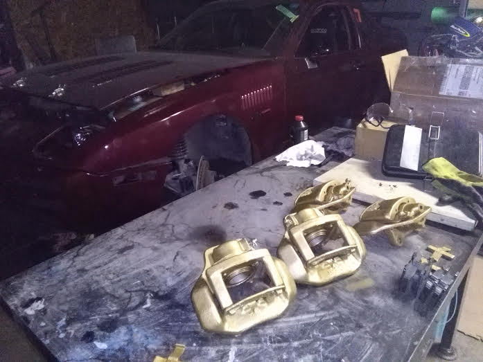
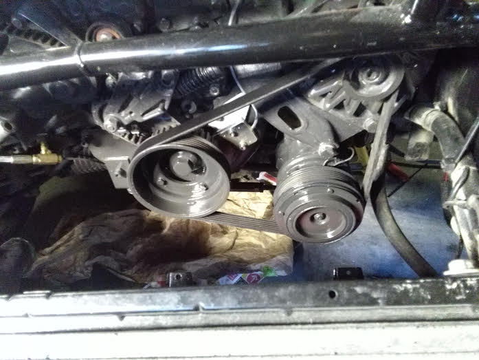
Painted the AC compressor. This is what my power steering delete looks like.
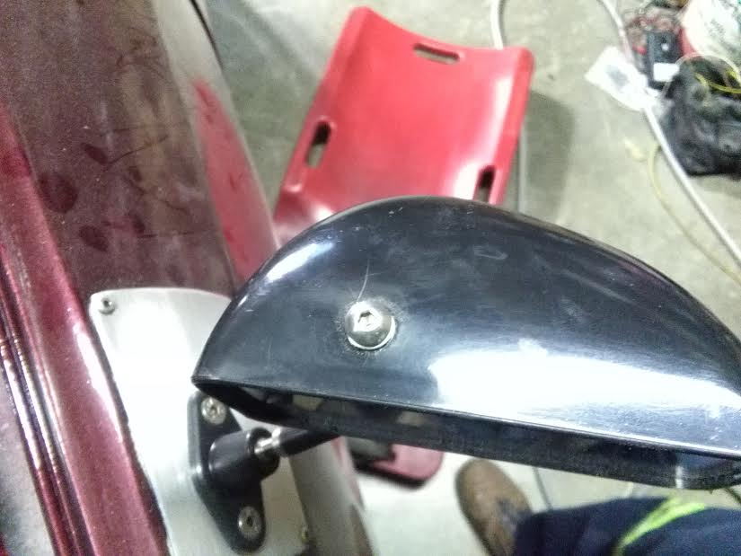
Happened to notice my brand new SPA Designmirrors have spider cracks in the plastic housing near the screws. I just sent them an email.
