When you click on links to various merchants on this site and make a purchase, this can result in this site earning a commission. Affiliate programs and affiliations include, but are not limited to, the eBay Partner Network.
Ask if Tom can cut the rubber from the fittings and tubes sections, and trash the rubber. You already have the rubber and the needed lengths/clocking, so you just want the metal parts. The metal can be cleaned for shipment, while oil-soaked rubber parts not so much.
Were it me, with your ready access to industrial-strength SS instrument tubing, benders and with the double-flaring tool, my corroded bits would be relatively corrosion-proof new metal in a heartbeat. Just sayin'... 10mm is ever so slightly smaller than a standard 3/8" tubing, close enough that you can easily use the 10mm connecting nuts over it. 8mm is within a few thousandths of 5/16" tubing, although I don't remember any 8mm sections in those runs.
While I don't regularly recommend deviating from the factory's original plumbing plan, consider that some of those rubber connections are there to make initial car assembly easier, since they wanted to lift the assembled driveline up to the tub as one assembly. You can easily justify some economizing on rubber sections that do nothing for you now, like the ones over the catalyst. Plus rubber sections that aren't there will never leak, degrade, cause a fire, etc. IMO, the tubing should have been attached to the tub as the fuel, AC and brake lines are. Too late for that now.
Hi dr bob!
You bring up a good point. However, I am not sure where you think I work, but we have none of that here. There is no SS anything, and my tubing choices are limited. Nothing metric. So, I am on my own.
However, my local NAPA has some DIN tubing. I bought 6mm for brake lines for the Red Witch. I am hope that they have 10mm tubing. The sections of transmission line that are heavily corroded are relatively straight, with simple bends. My defective Bend-Fu should be able to handle that. I can use my double flaring kit to make bubbles to use for hose retention. At this point, if I go the route of bending my own replacements, I don't think I am going to reinvent the wheel. See my aforementioned statement of defective Bend-Fu. I can ruin tubing faster than anyone I know.
On the other hand, I am going to contact Tom again and find out specifically why 928 Intl cannot ship the lines. If possible, I would have them cut out the rubber sections and just send me the metal lines and all the fittings. We shall see.
if i remember right, its because
1- i dont think they even keep them, i dont remember seeing any around, people get new ones made
2- LONG, and shipping without getting them damaged would be expensive.
i made my own lines for my "electric diff pump" project from the front of the car to the back. all you need is to braze some fittings to stock sized tubing.
Thanks, Ducman82. That makes sense. The more I think about it, the more I'm going to stop off at NAPA Monday morning on my way home from work.
I am of two minds on this:
-get 10mm DIN tubing, use my double flaring kit to make a bubble at each end for hose retention. However, I don't have any metric tubing benders. I am not sure how well 10mm tubing will bend in a 3/8" bender.
-get 3/8" tubing, and inverted flare fittings to screw on the ends. Get fitting that have a 3/8" barb on the end.
My main concern is getting a leak free seal from the 10mm hose to whichever method I go to. If need be, I will order more clamps from Greg and Mary Brown and double clamp the connections.
Thanks! Monday, I am going to do something about this.
At the time of purchase, Auto Assets replaced the rubber hose on two sections of one of the transmission fluid lines on the Red Witch.
I am now replacing all the rest, using Greg Brown's bulk hose and clamp kit.
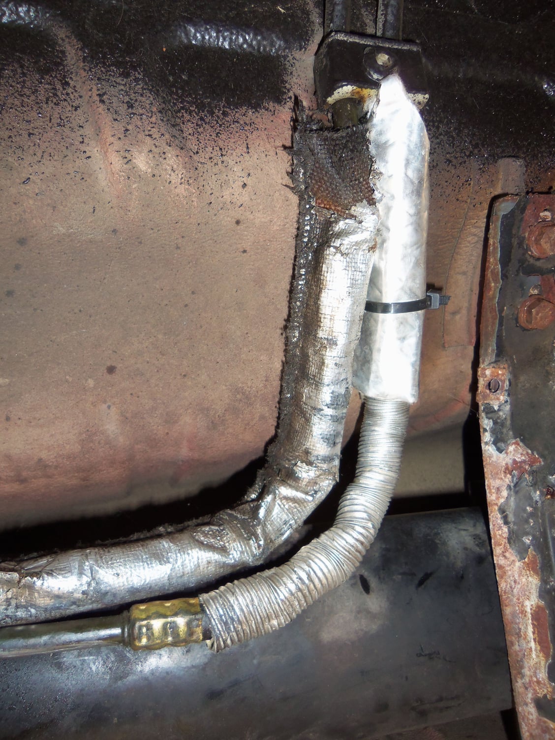
There is some factory looking aluminum covered cloth sleeving over one line, and a mishmash of sleeving over the other line. These are the 90 degree flex sections above the catalytic converter (if the Red Witch had one. )
So...what would be a good fire sleeve and/or abrasion sleeve for the rubber sections of the transmission lines? Should I only cover those above the catalytic converter area? Or, should I cover at all three areas? At the transmission, above the catalytic converter area, and up front at the radiator and remote cooler?
I don't know squat about fire sleeve, so I am open to suggestions. Last time I dealt with it was on GE LM2500 and Allison 501K-17 gas turbine engines. 16 years ago.
Soooo...I am open to any and all suggestions.
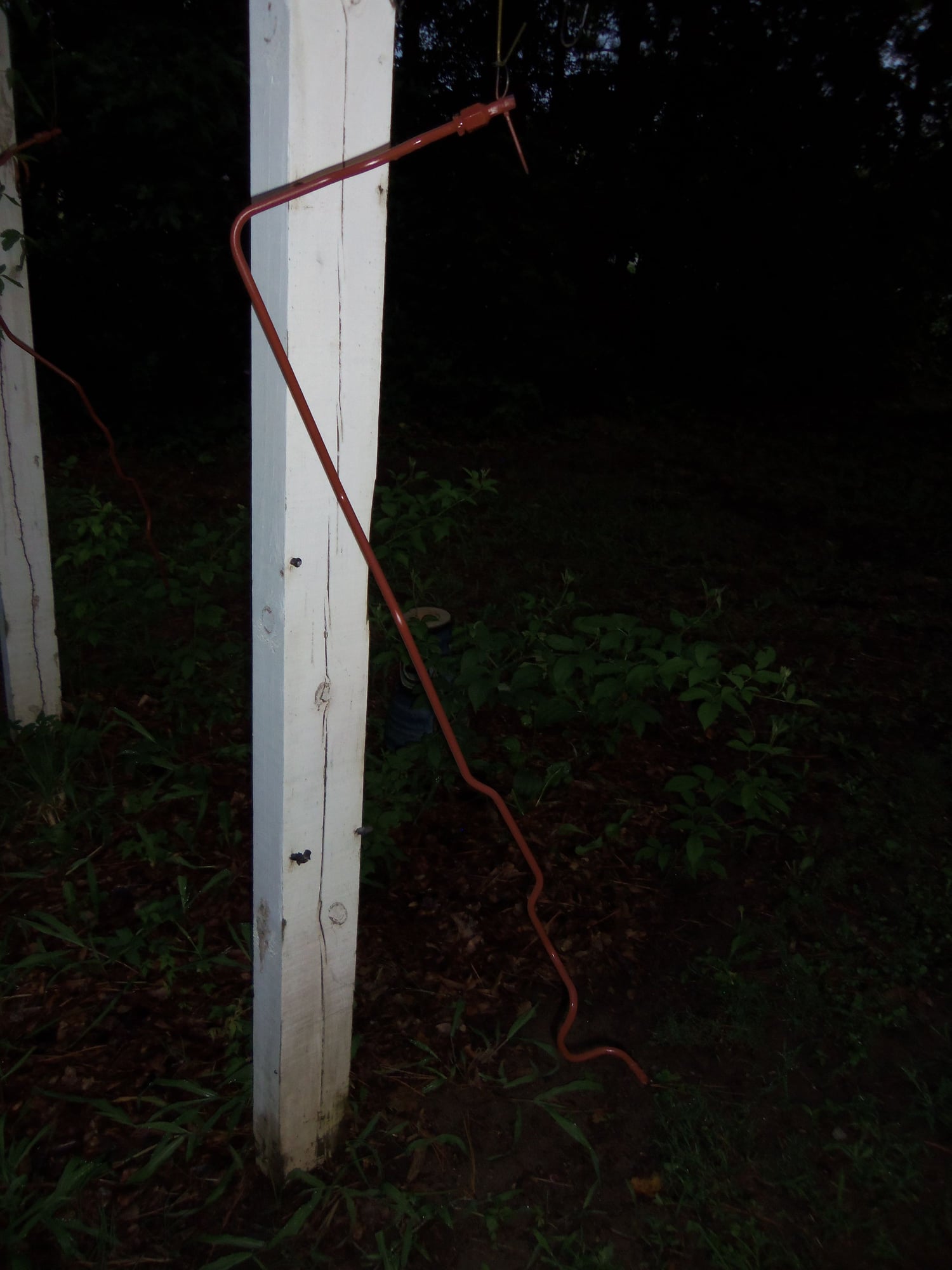
Sleeving in question.
Corrugated sleeving, and brass crimp added at time of rubber hose replacment. Woven sleeving looks to be factory.
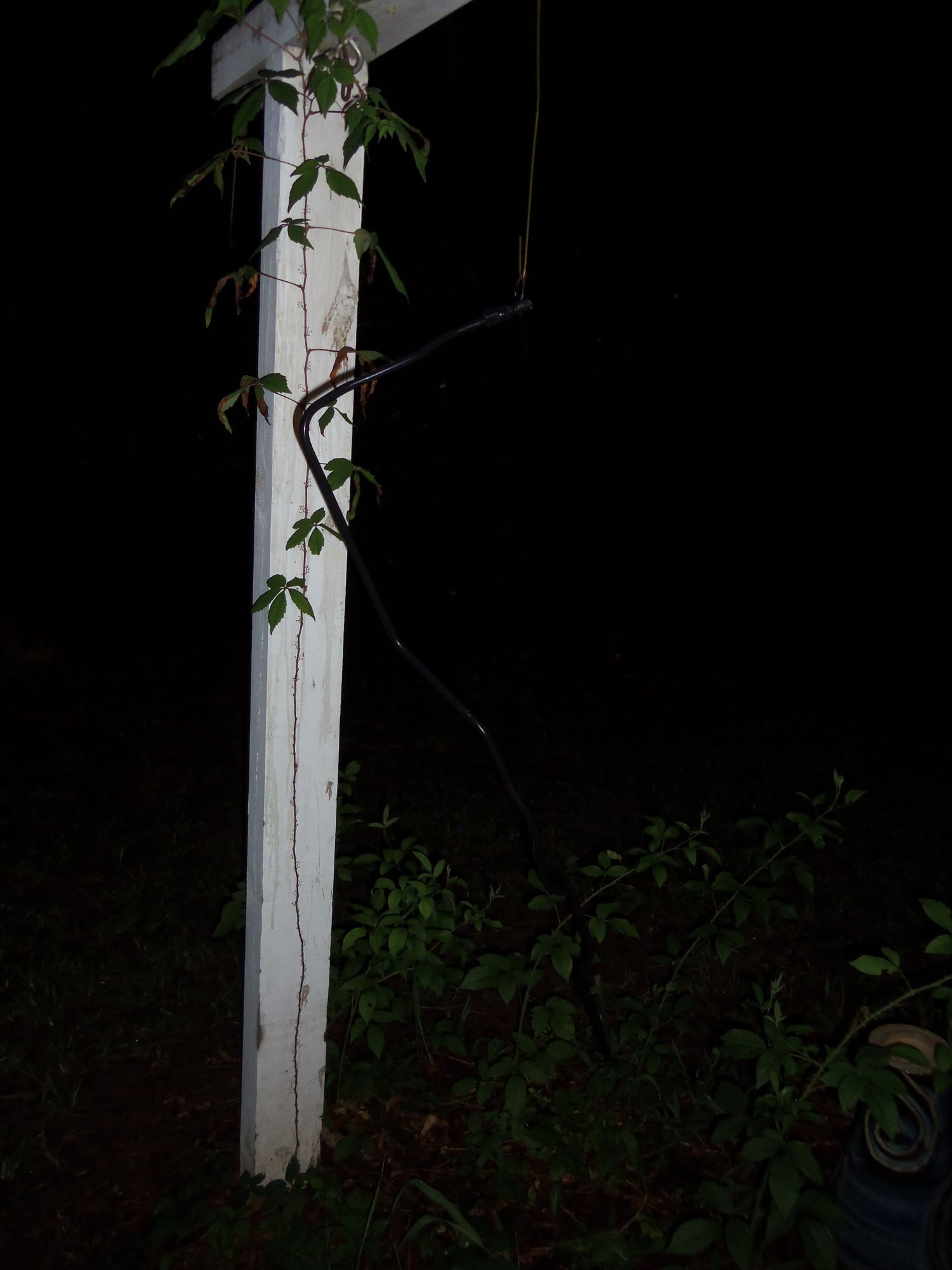
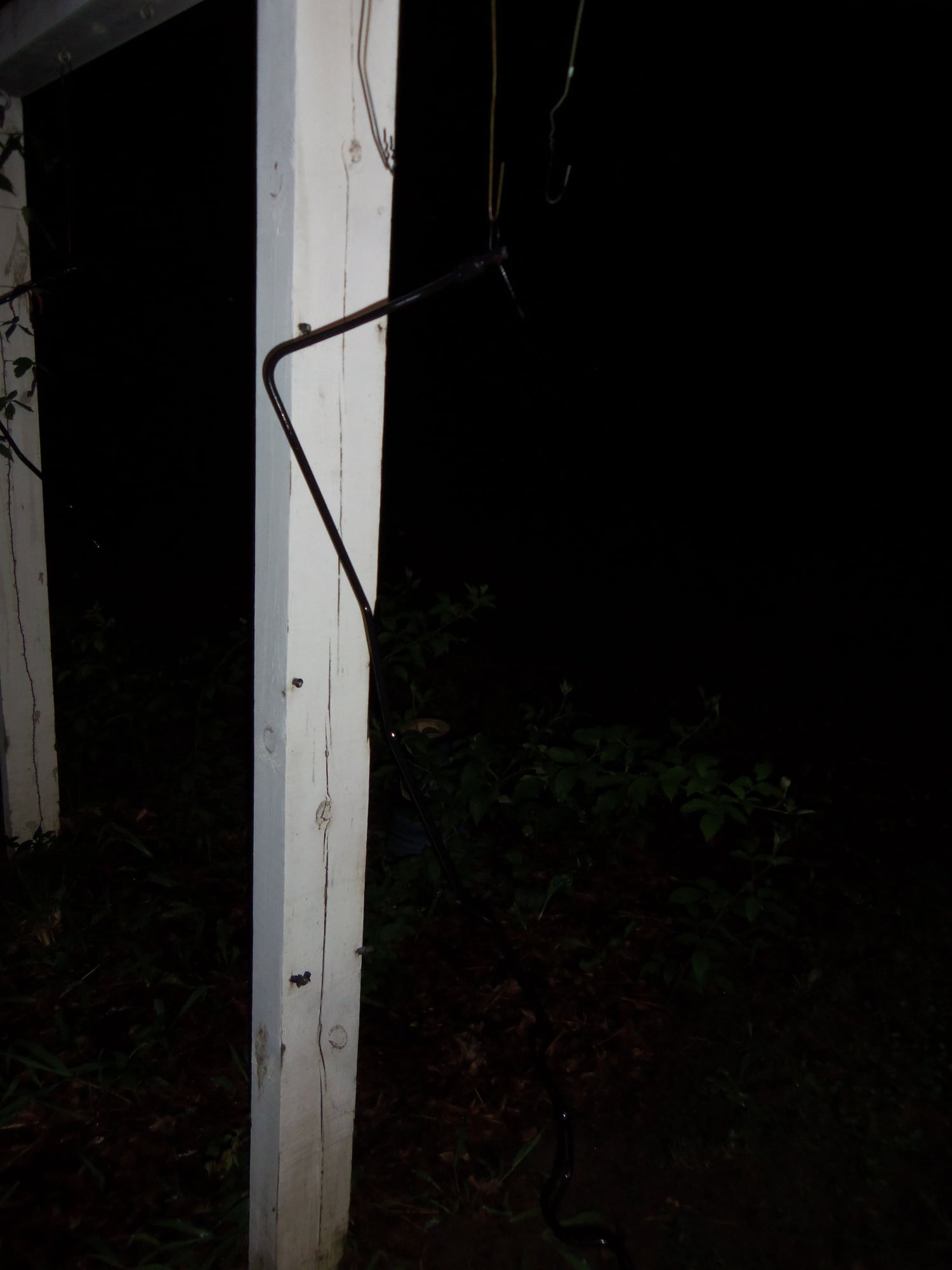
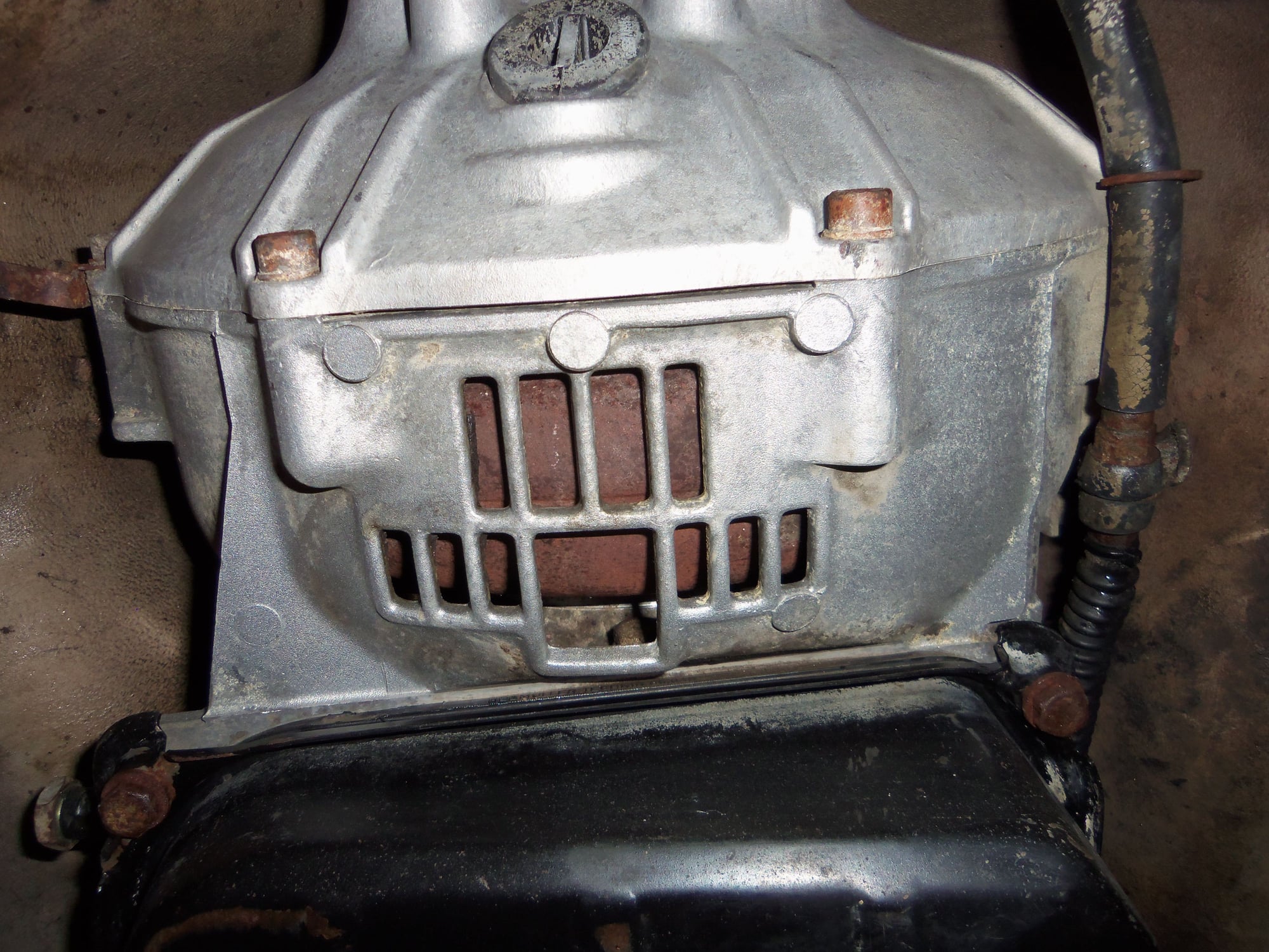
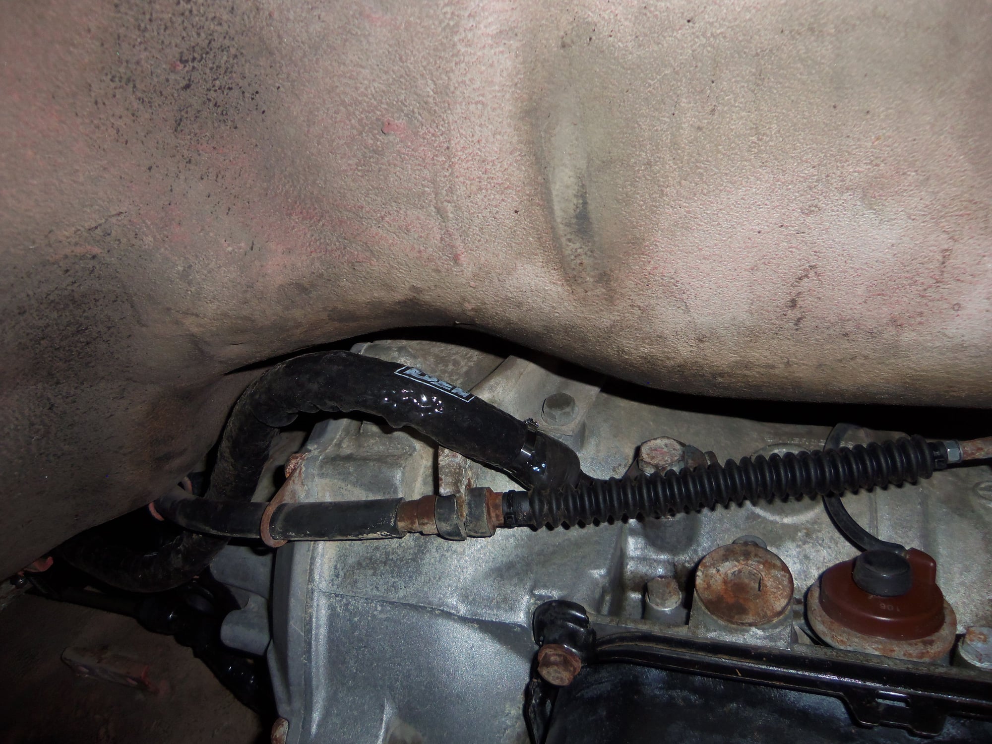
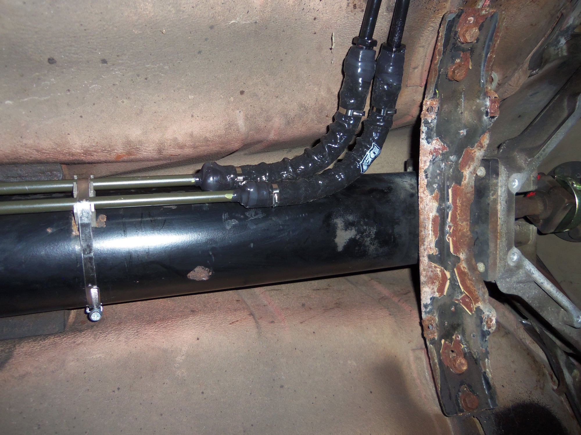
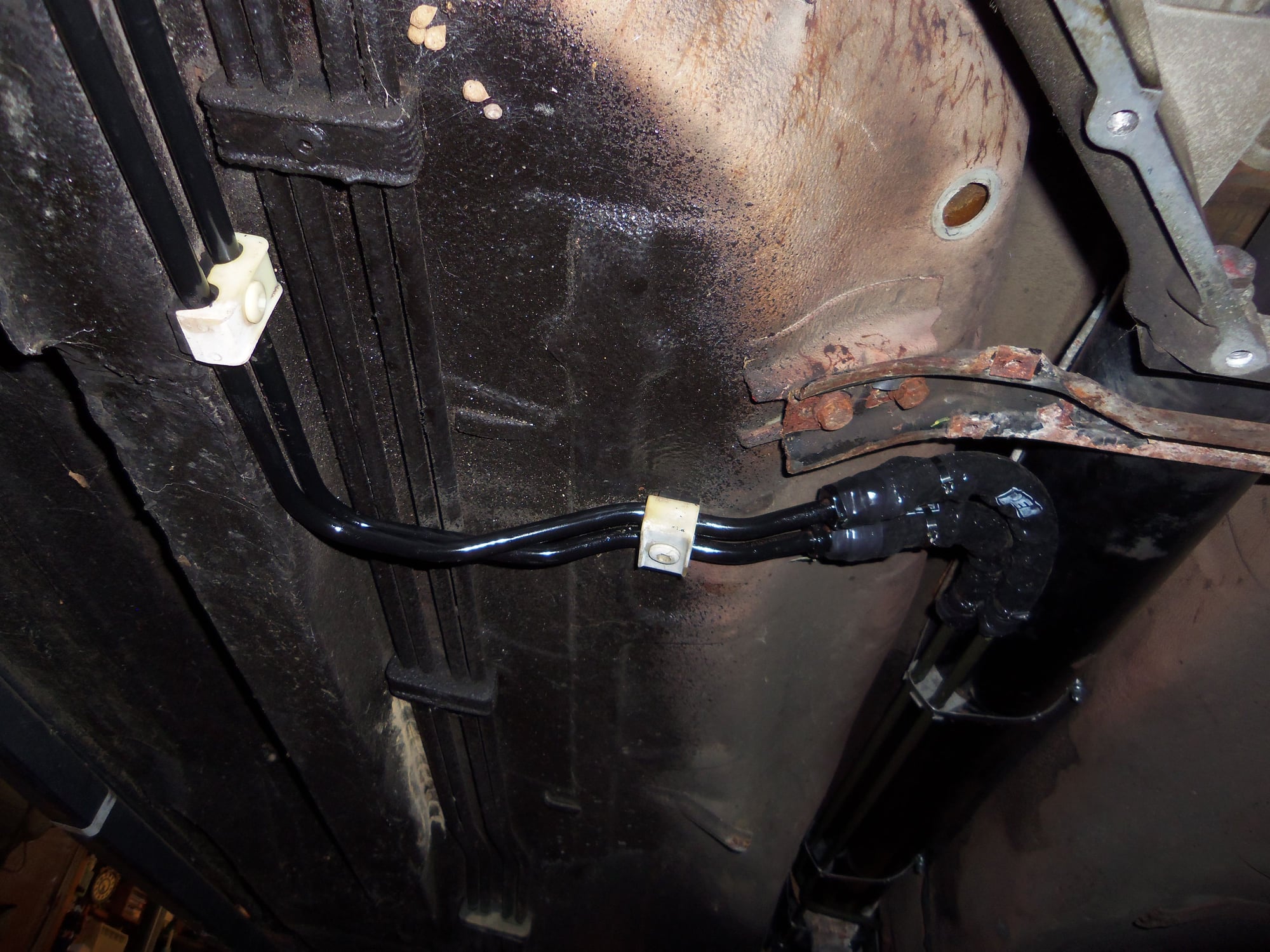
Routing of hoses above catalytic converter area.
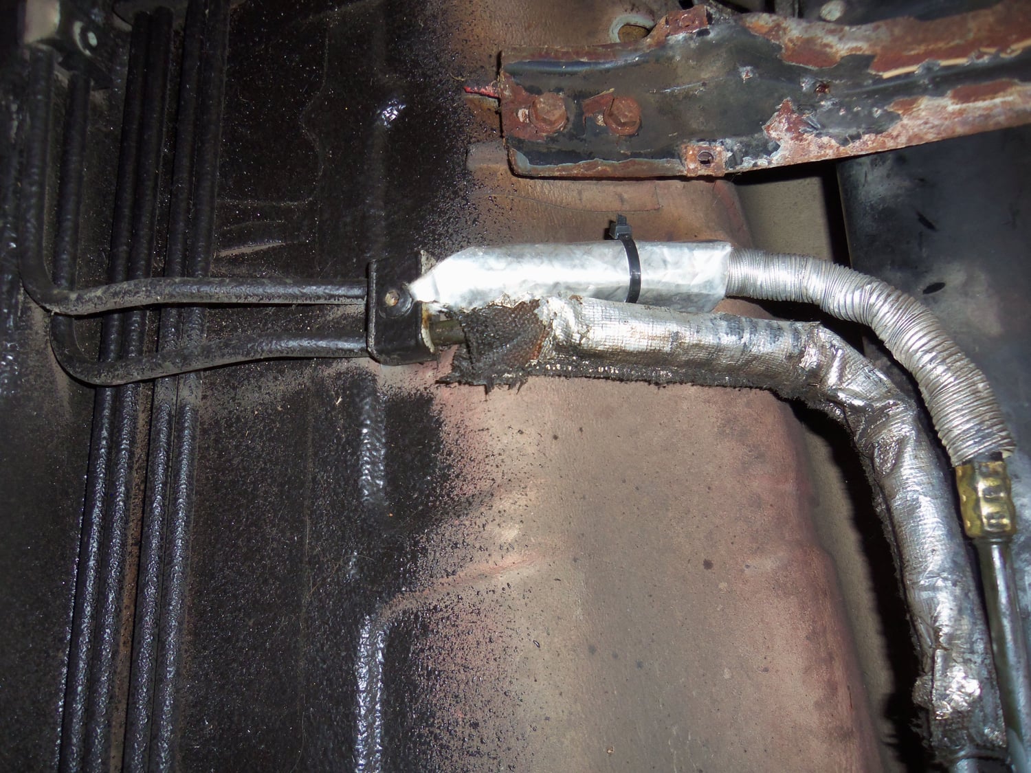
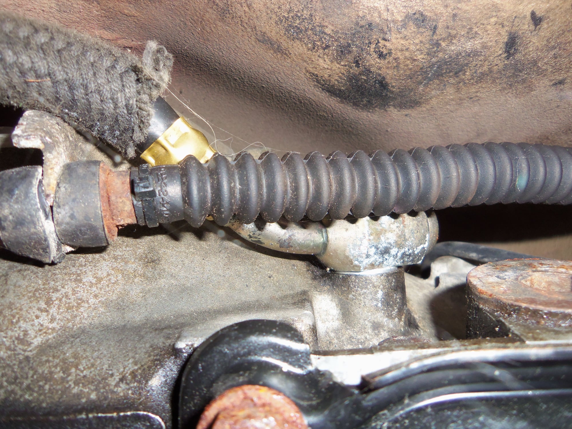
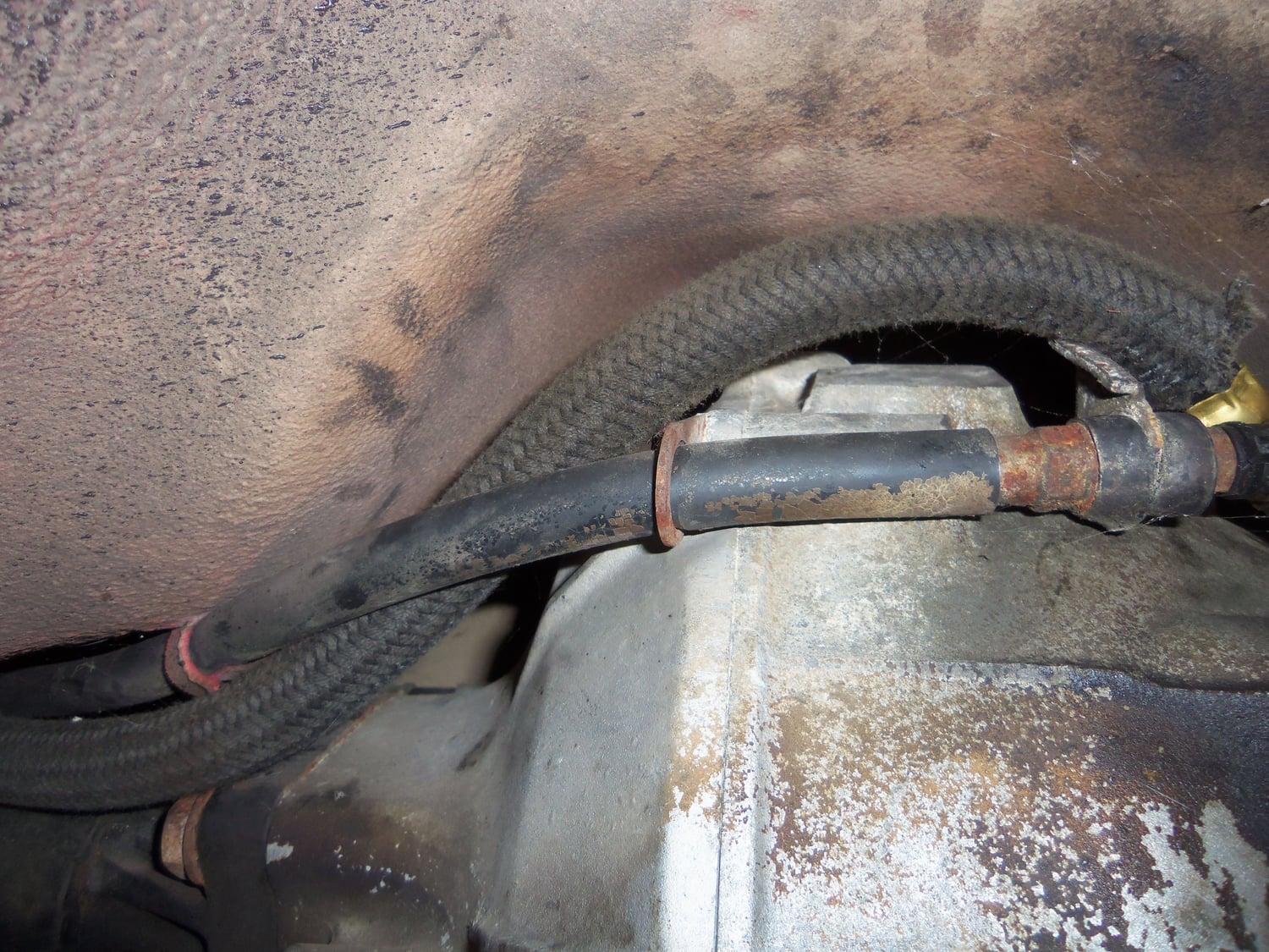
Rubber hose at the fill point connection on the passenger's side of the transmission.
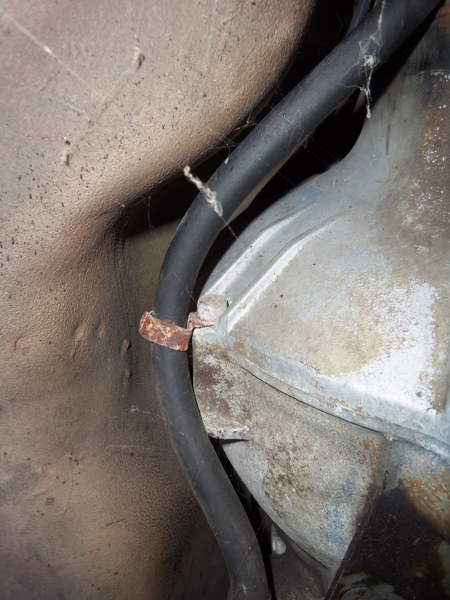
Where the hose routes along the torque converter housing on the passenger's side.
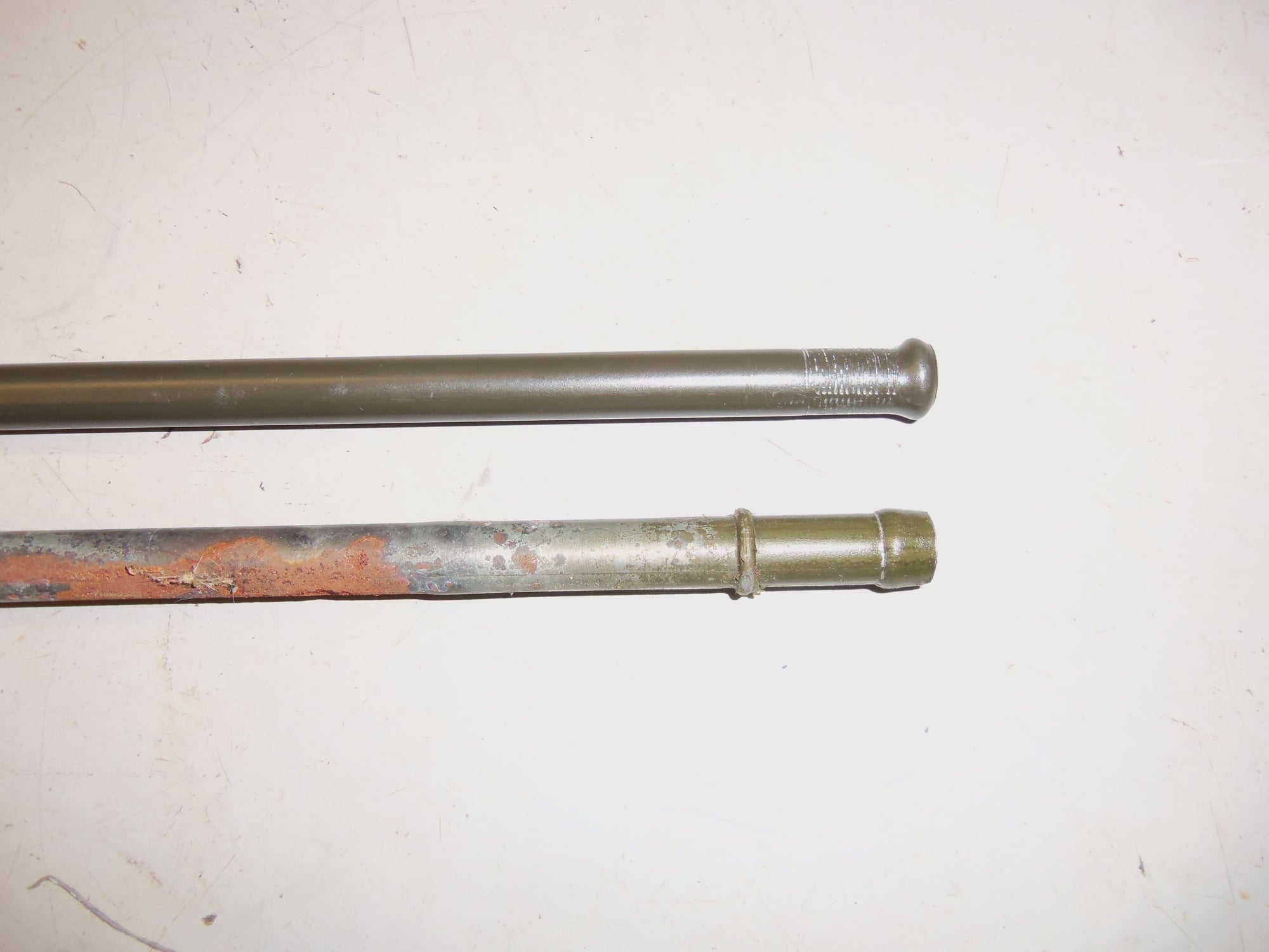
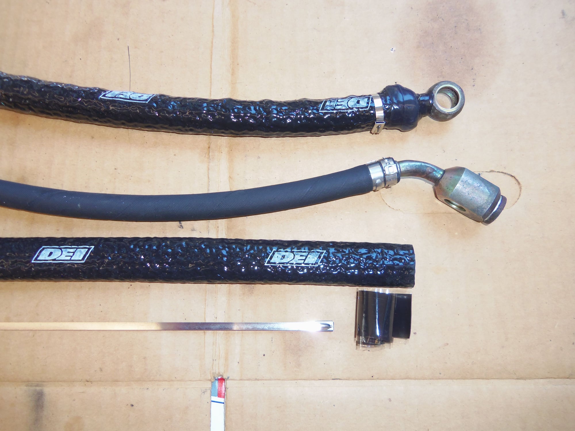
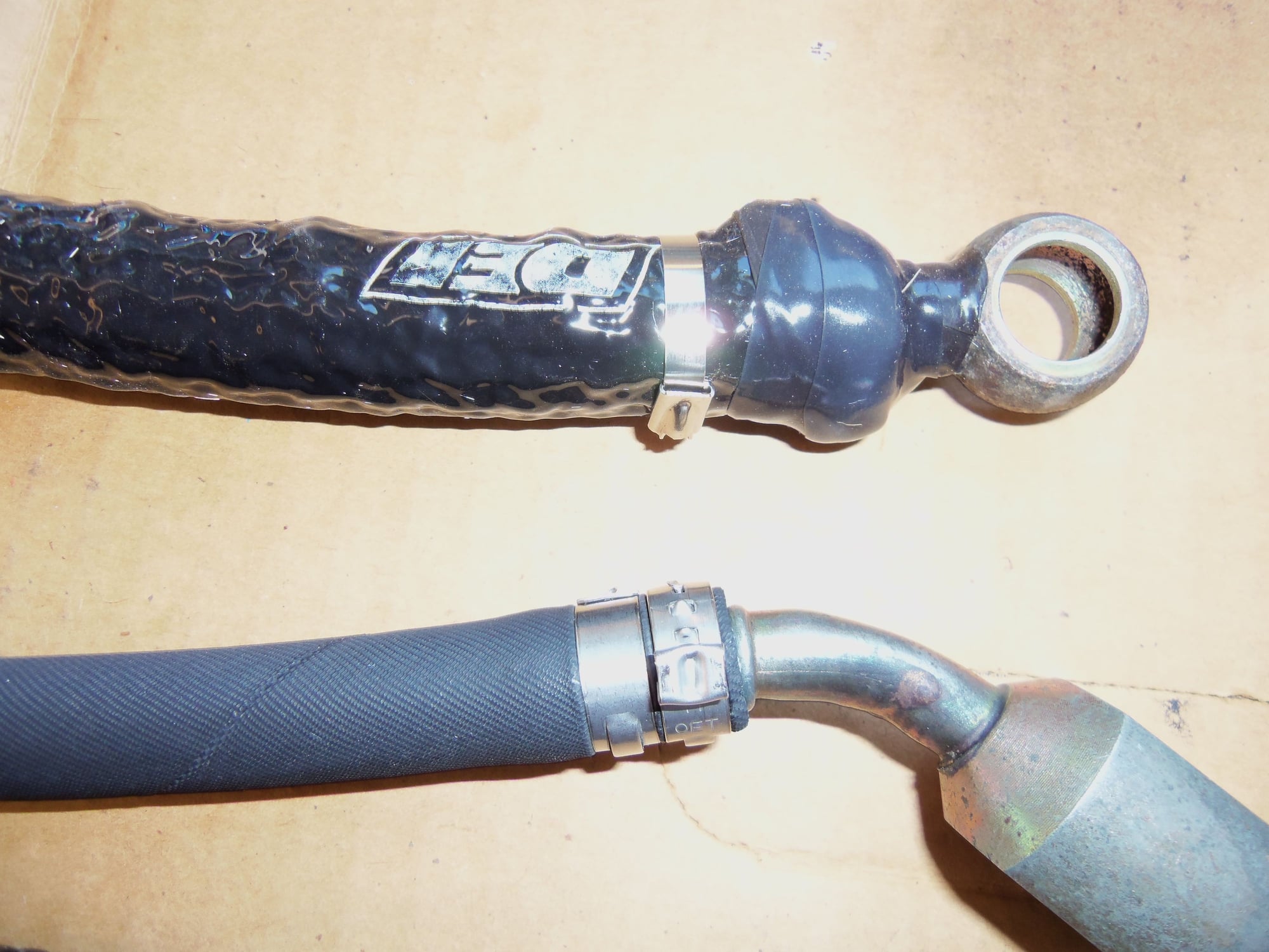
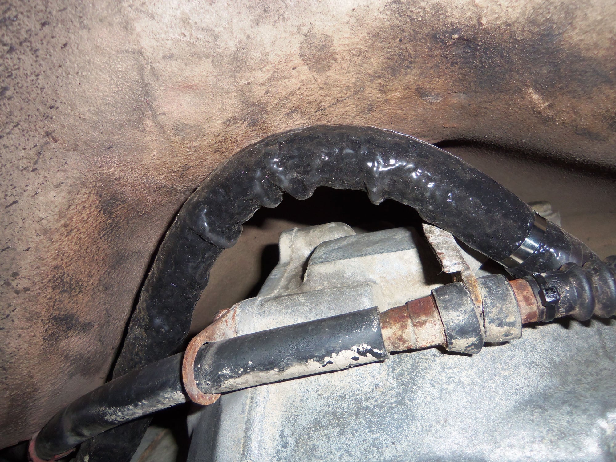
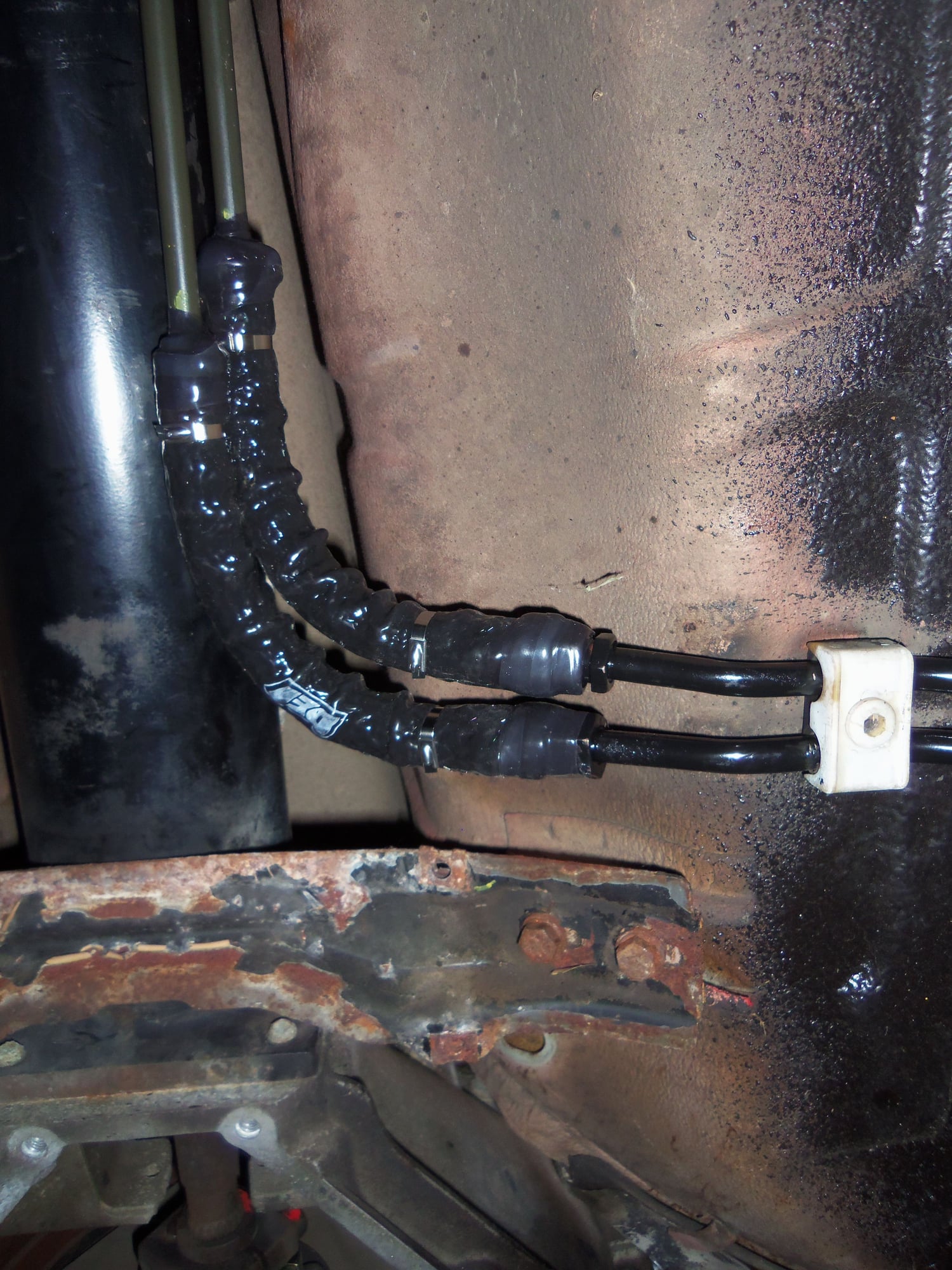
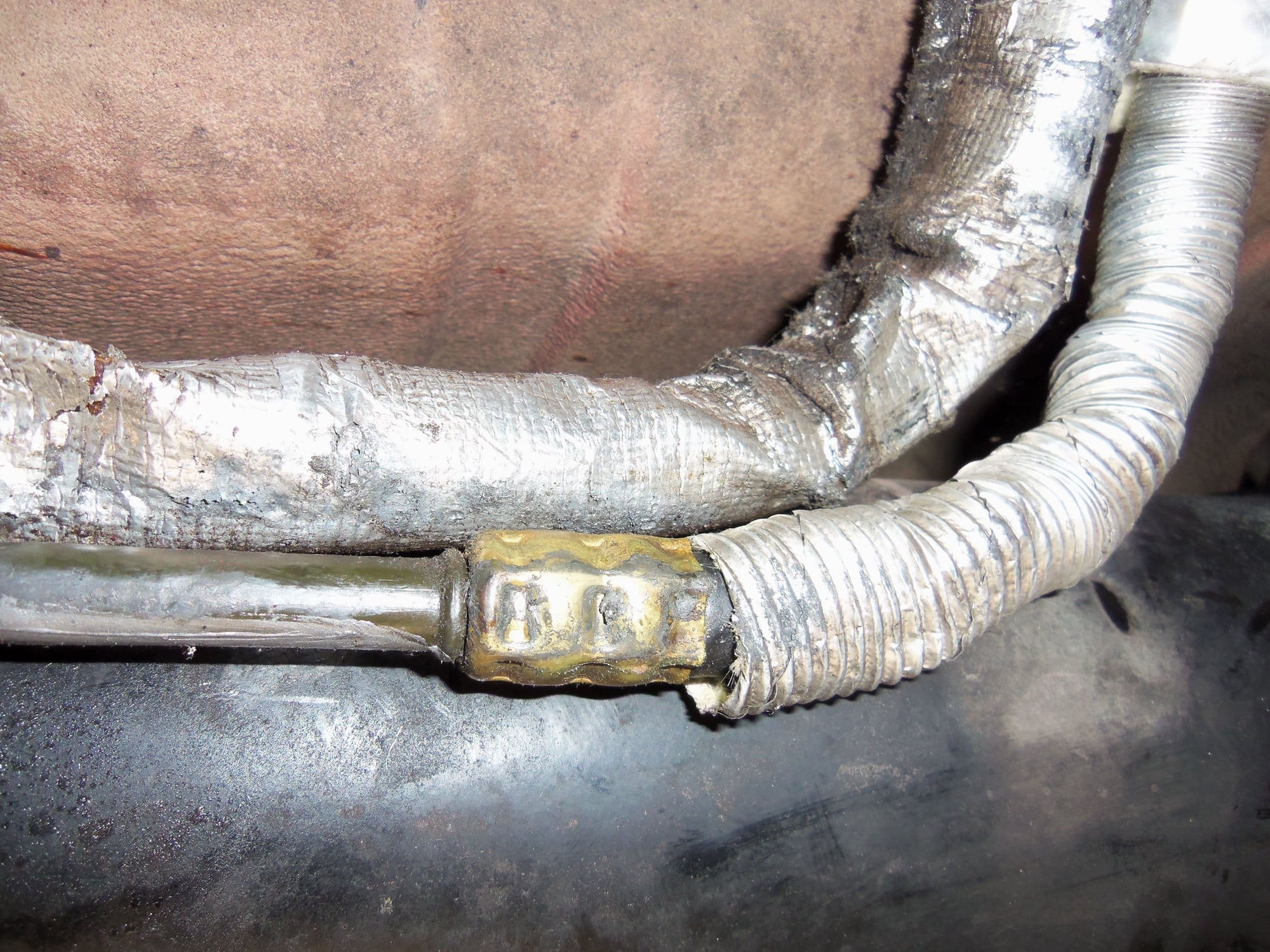
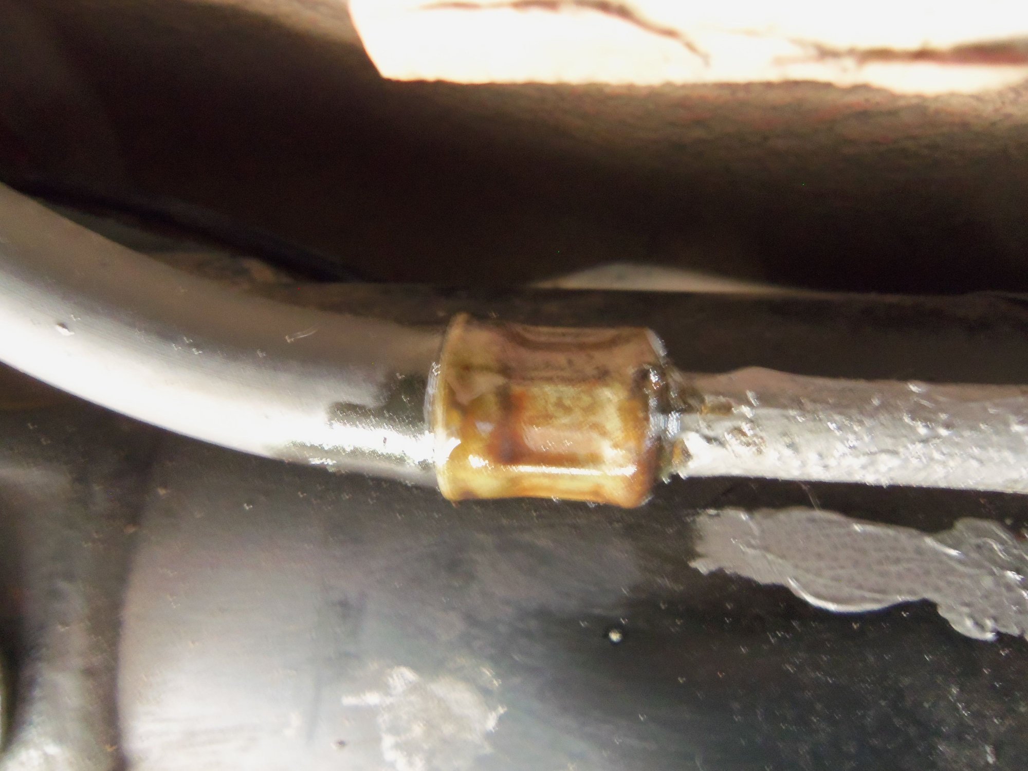
Factory hose at top. Replaced hose at bottom, with brass crimp and some kind of braided sleeving.
Factory crimp is starting to leak. This is why I am replacing everything.
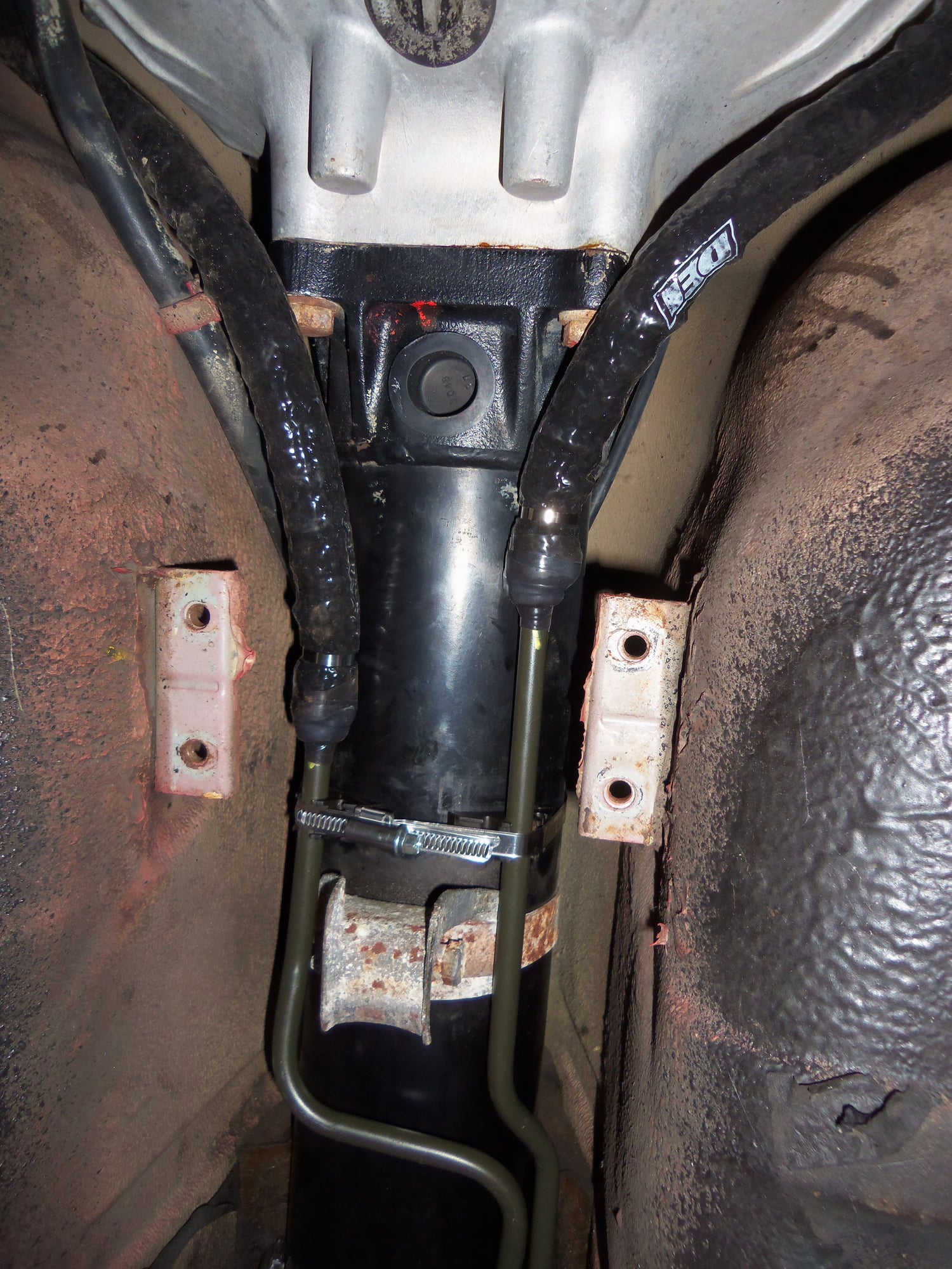
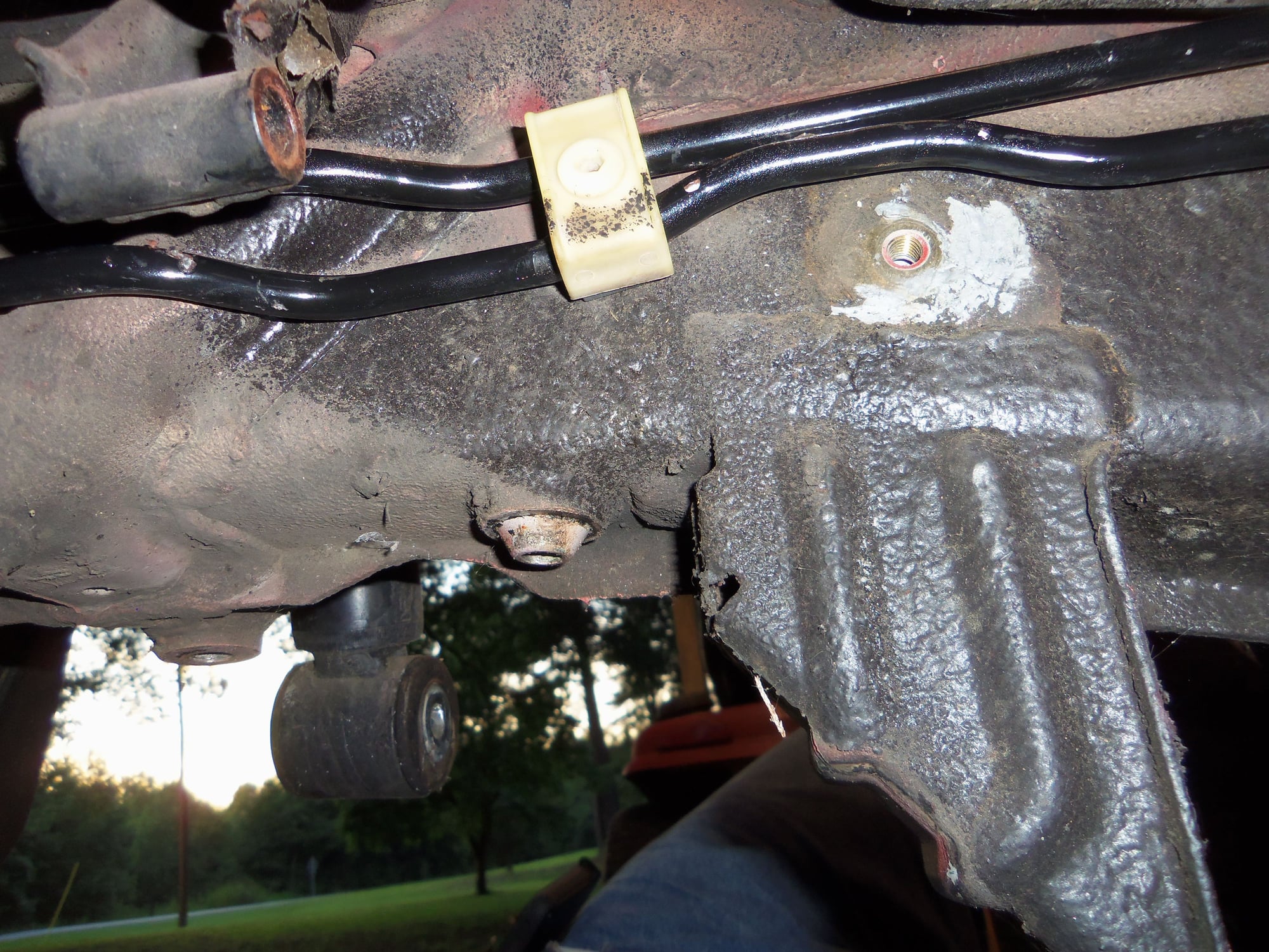
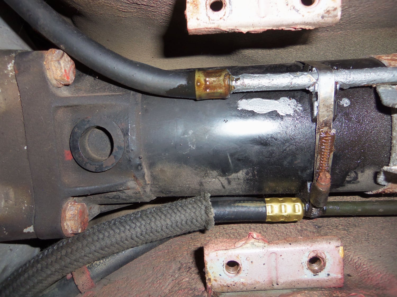
Connection on the driver's side of the transmission, showing new hose, brass crimp, and braided sleeving.
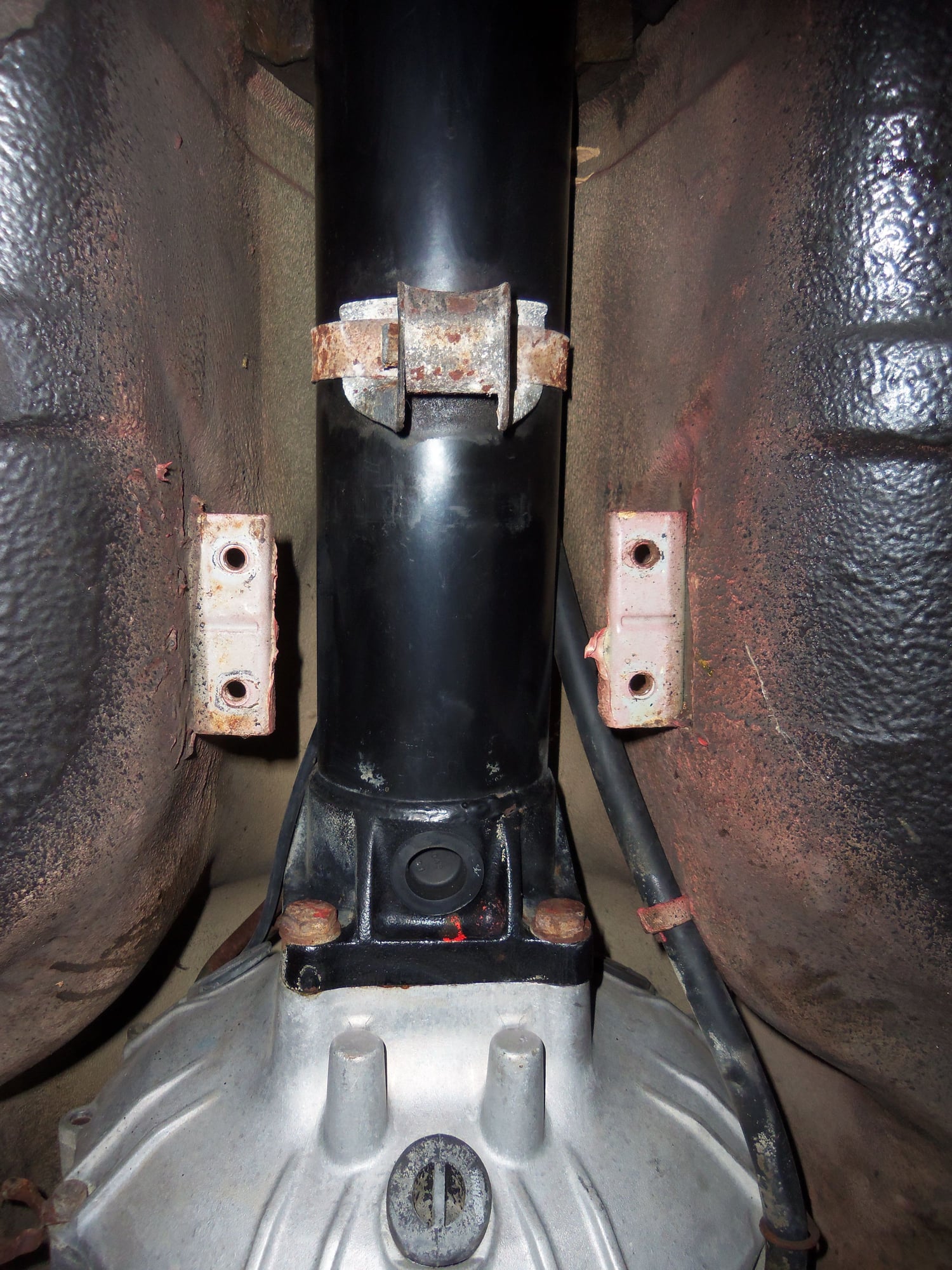
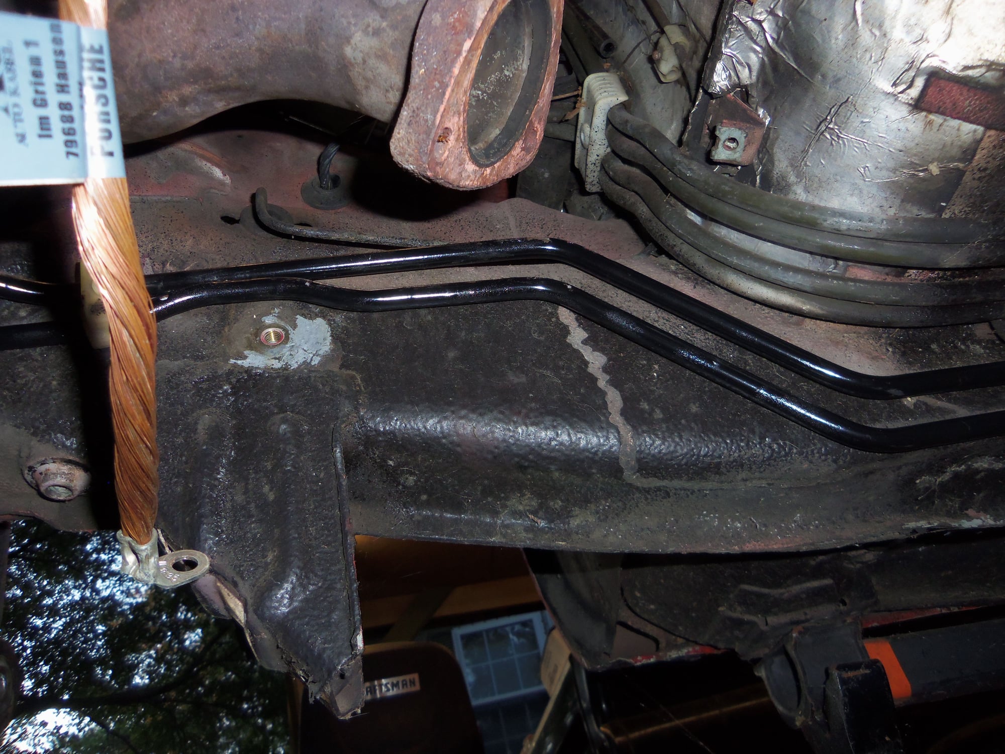
Routing of hose/sleeving along the torque converter housing, with the shift cable, on the driver's side.
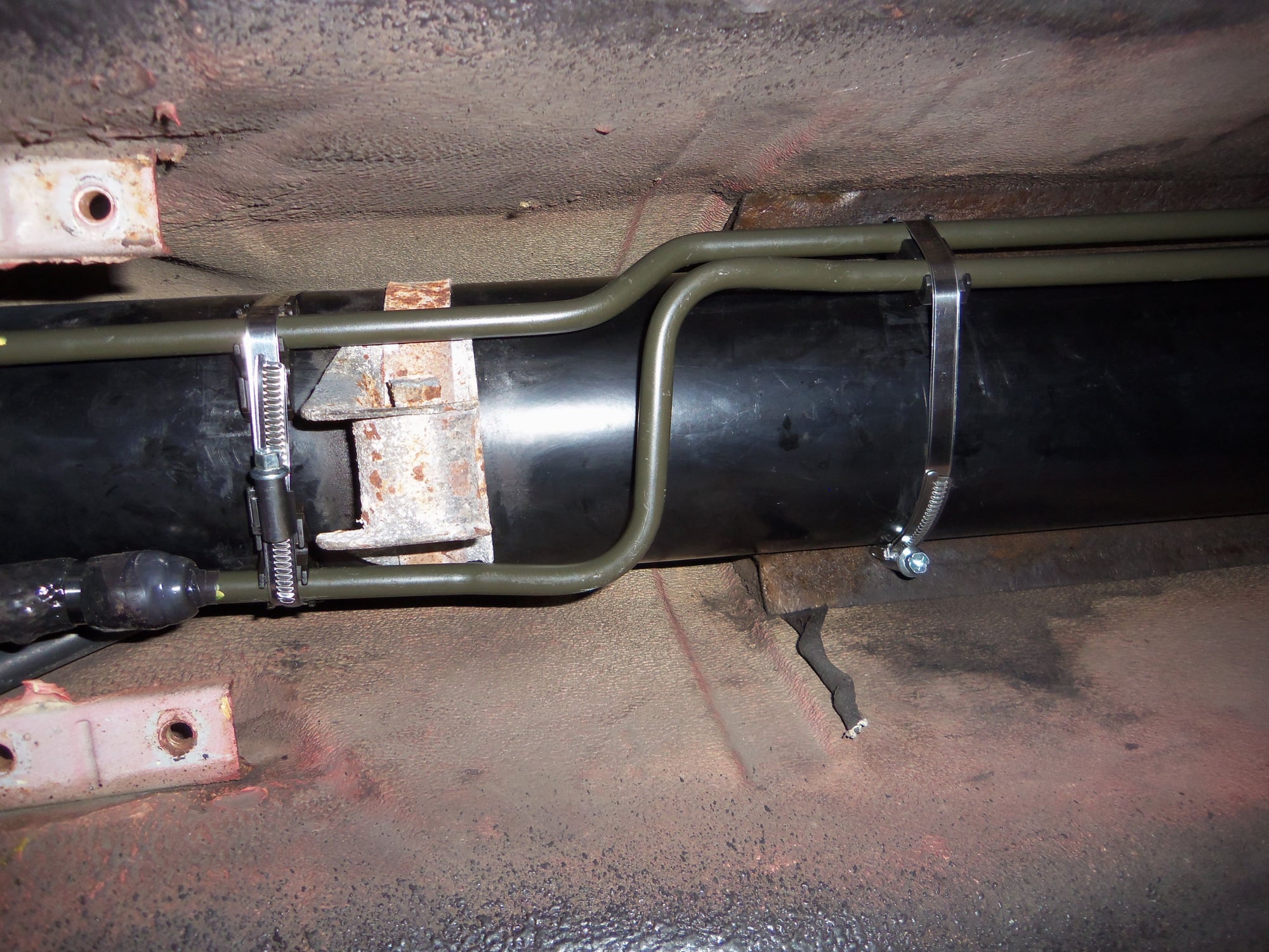
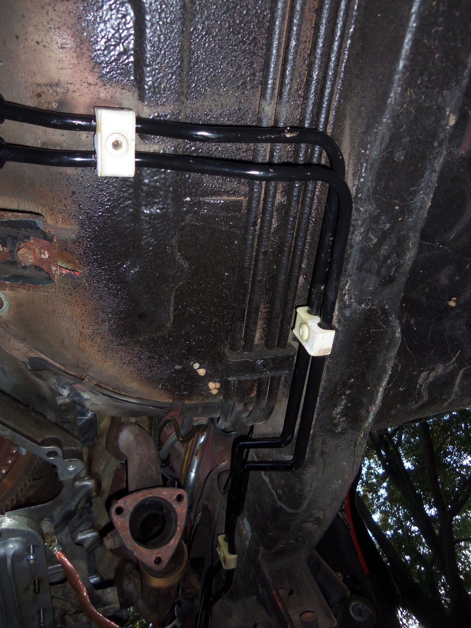
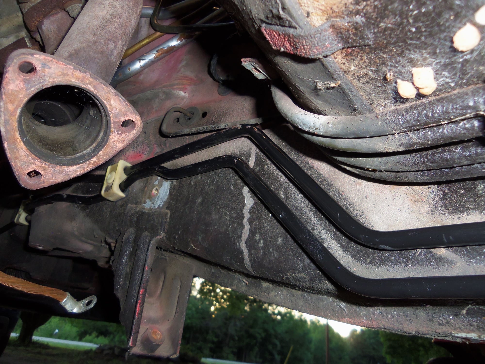
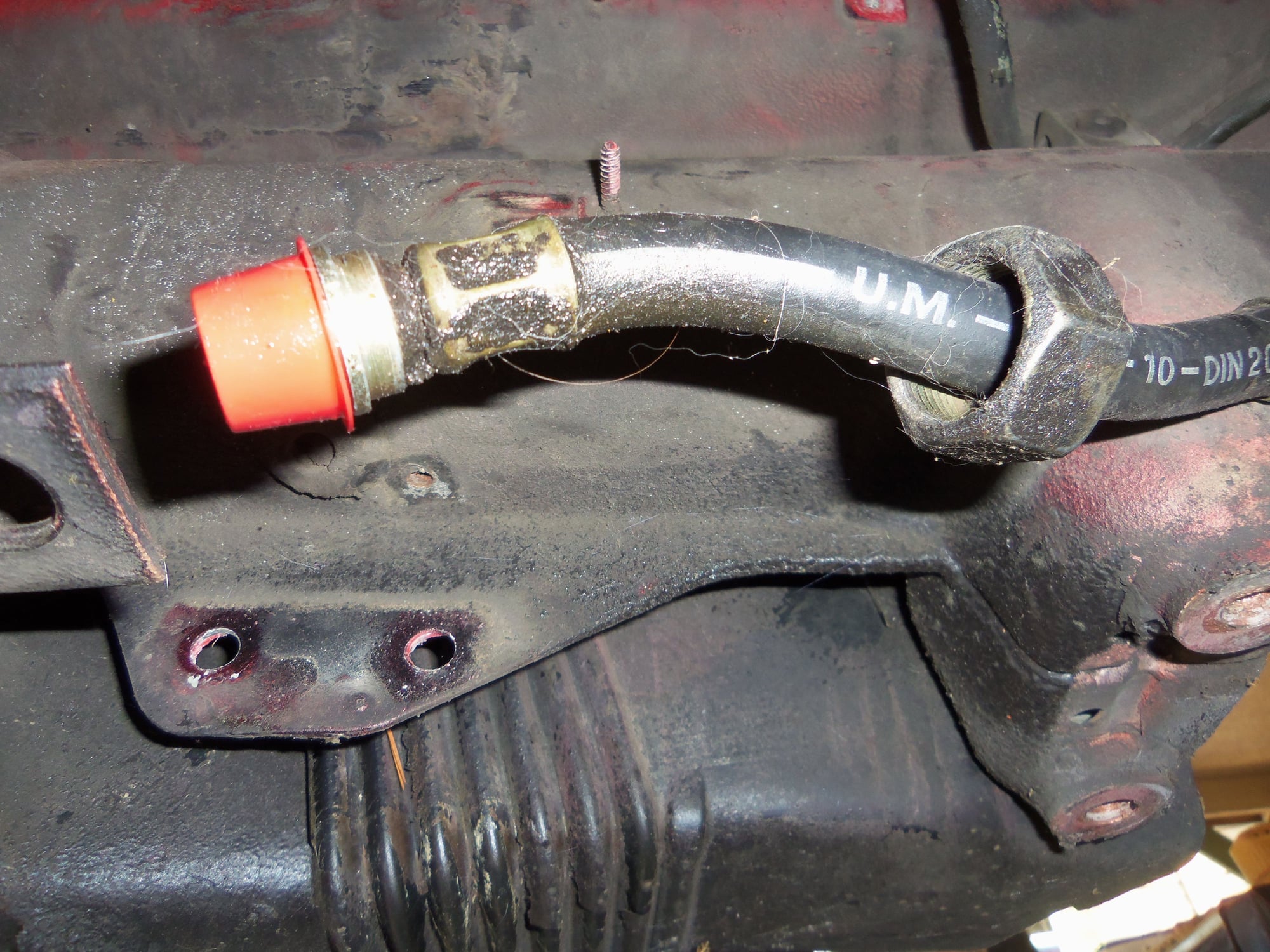
Short rubber hose at the front that goes to the lower cooler fitting in the radiator.
Long rubber hose at the front that goes to the remote transmission cooler behind the grille.
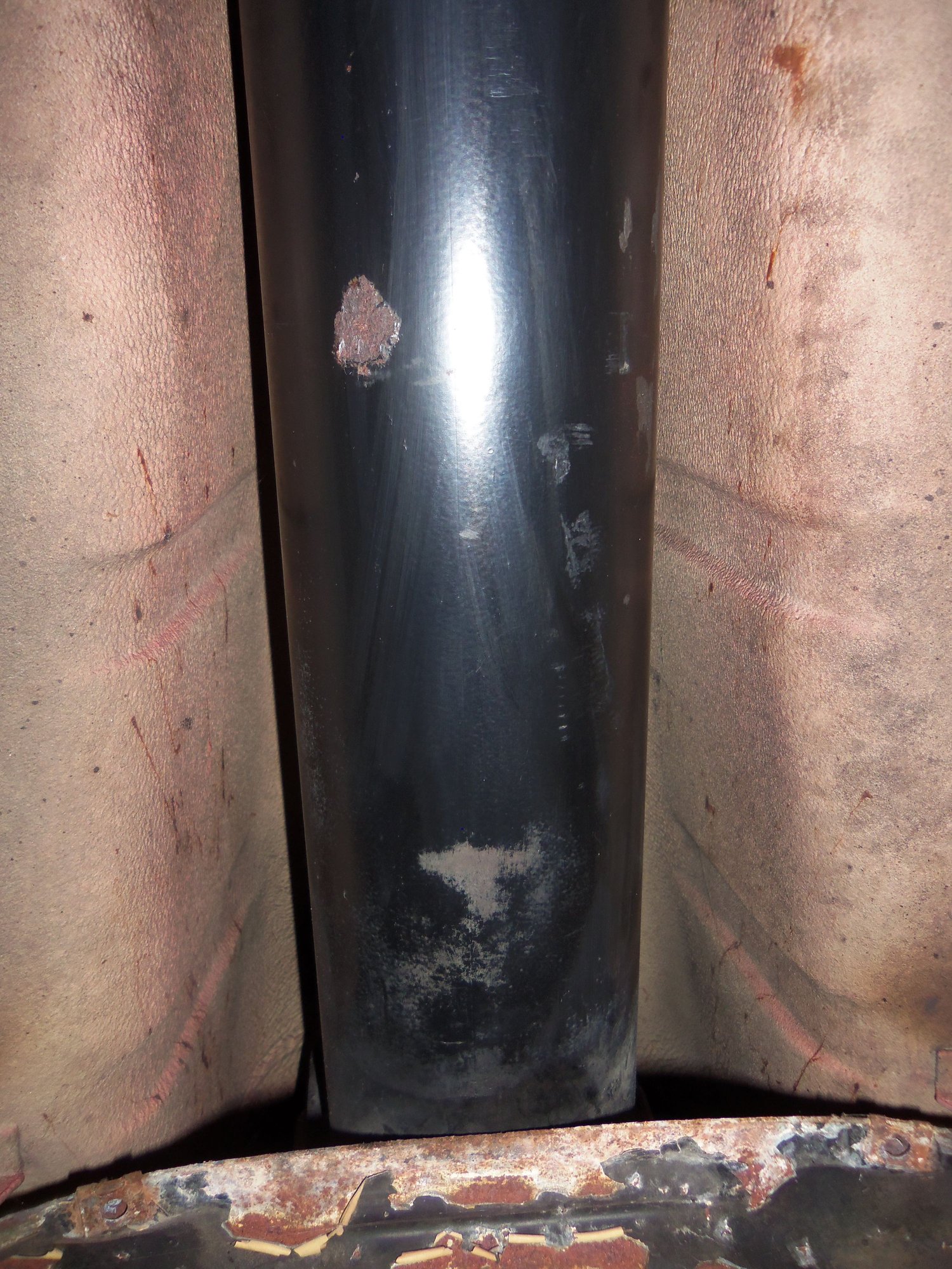
I am completely removing both lines. Yes, a bit of trouble. But, I will be able to work with removing the factory crimps from the relative comfort of the work bench. That, and there is some surface rust on the lines where they route along the torque tube. I want to deal with that.
I will loosely reassemble both lines in place under the car, then crimp the clamps down after everything is correctly clocked.
At the front, I will be incorporating a remote spin on oil filter for the transmission. I have ordered extra hose and clamps to account for that.
I don't think I am going to replace the two new hose sections that Auto Assets installed. The crimps look good and don't seem to be leaking.
I stock and sell a fire sleeve kit that works perfectly on these lines, to complement my transmission hose kits.....
Unless someone asks, I assume they are re-using their old pieces.
Unless you made a jig with the old lines, I suggest leaving at least one clamp on each line loose until you have the hose in place. The clocking on the rubber sections is critical.
Unless you made a jig with the old lines, I suggest leaving at least one clamp on each line loose until you have the hose in place. The clocking on the rubber sections is critical.
That is exactly what I plan on doing. I will crimp the hoses on the banjo fittings at the transmission. Then, as I go along, seating the metal lines in the plastic body clamps, I will crimp the rest of the hoses.
I'm so busy designing, testing, building, installing pieces on my own client's cars that there simply isn't enough time in the day to promote/market the products I make for these cars.
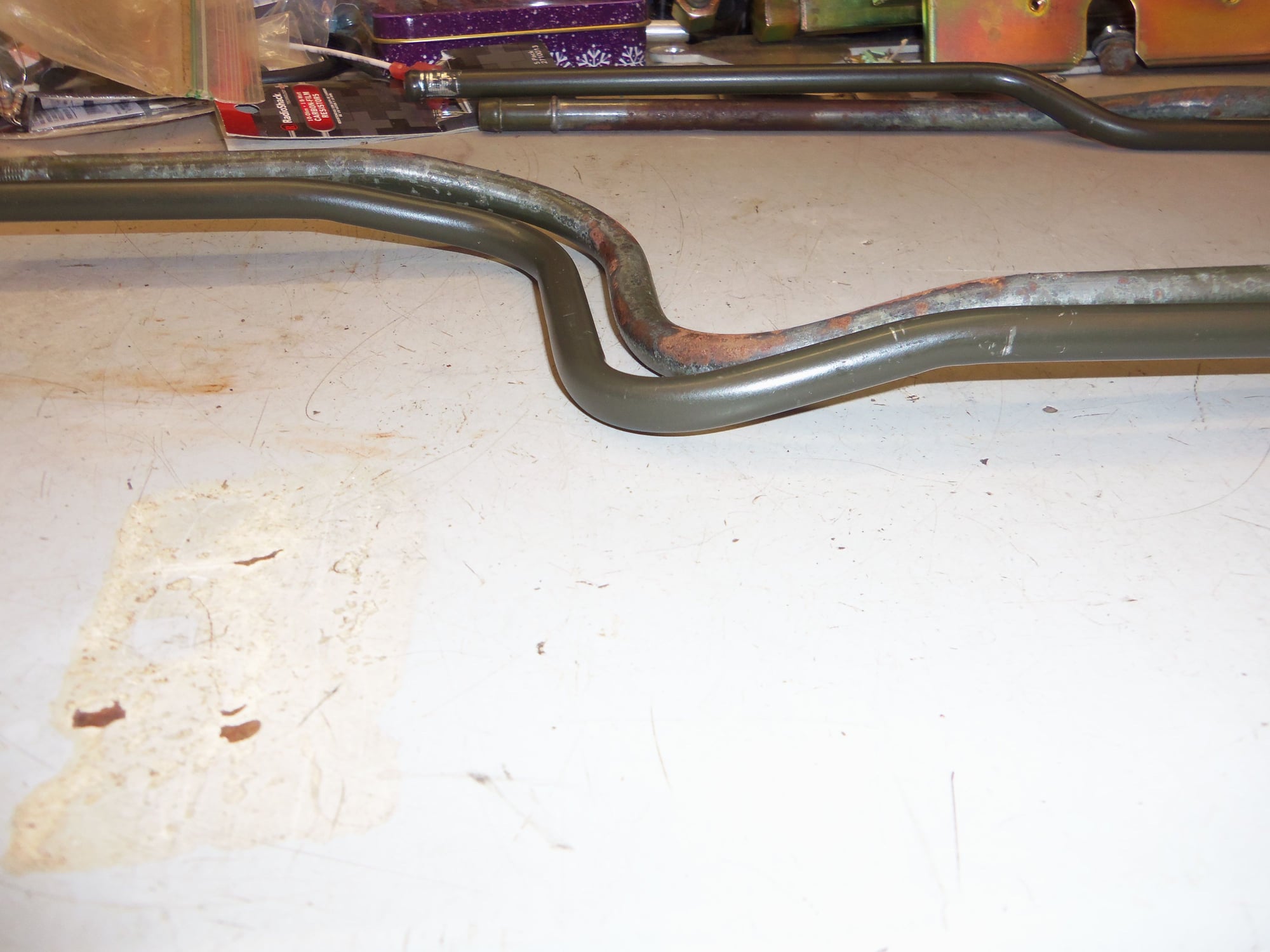
A few days ago, I wire wheeled the two front metal sections of transmission cooling line. I removed the corrosion and any loose epoxy coating. I then used a red scotchbrite pad to smooth out the surface.
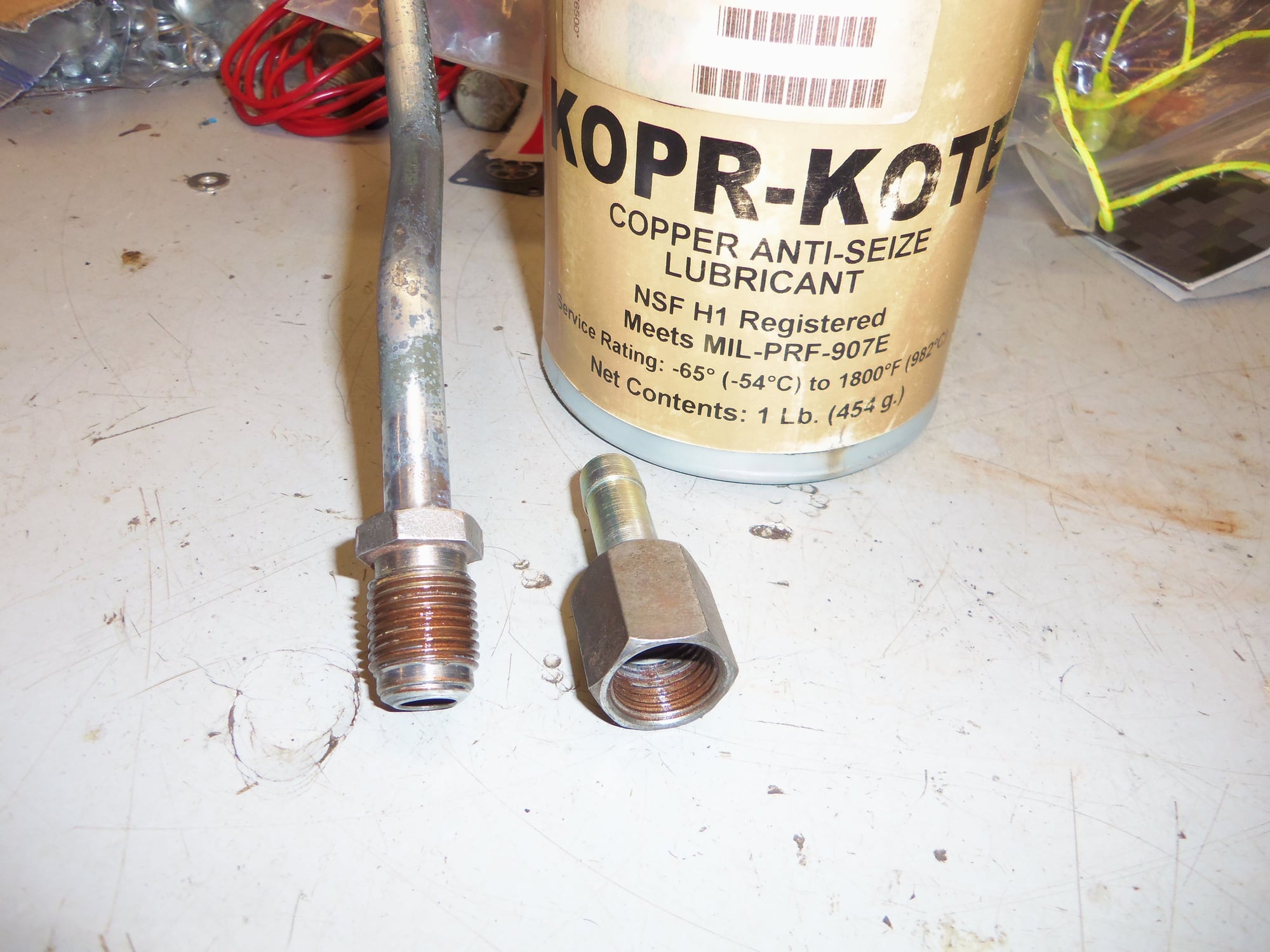
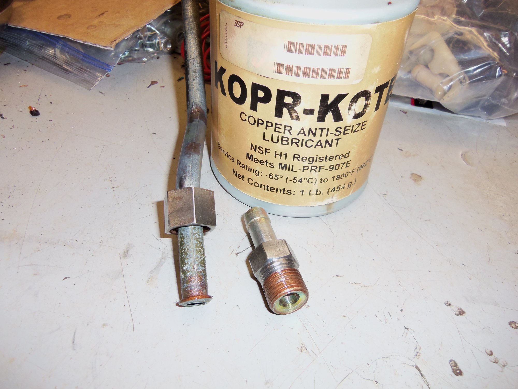
I assembled both threaded unions with copper antiseize on the threads, then cleaned any excess off so as not to foul the paint. I taped over the barbs only. Everything else got painted.
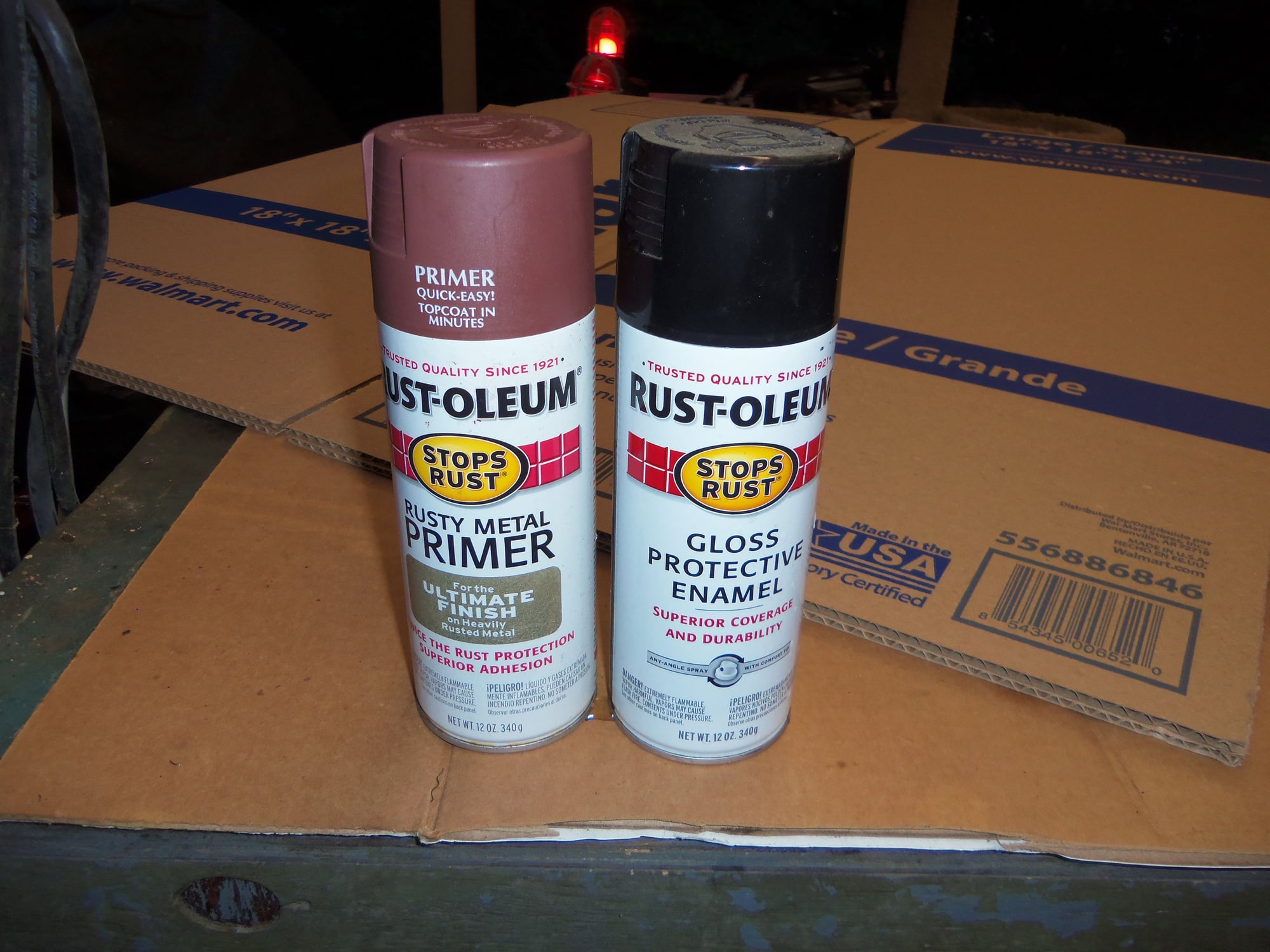
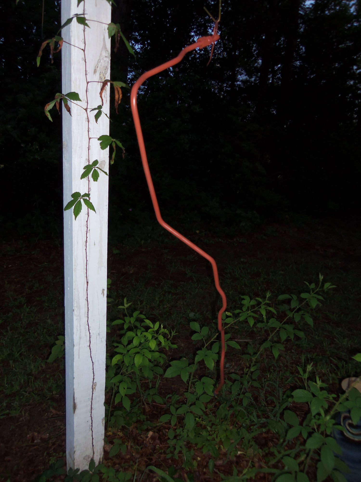
Both lines got a coat of Rustoleum Rusty Metal Primer, followed by a coat of Rustoleum Gloss Black. I was going for coverage and protection, not looks. And it shows.
I let the lines bake in my workshop in the South Carolina afternoon sun for a few days.
Lines ready for paint.
Barbs taped off. Zip ties are for hanging for painting and drying.
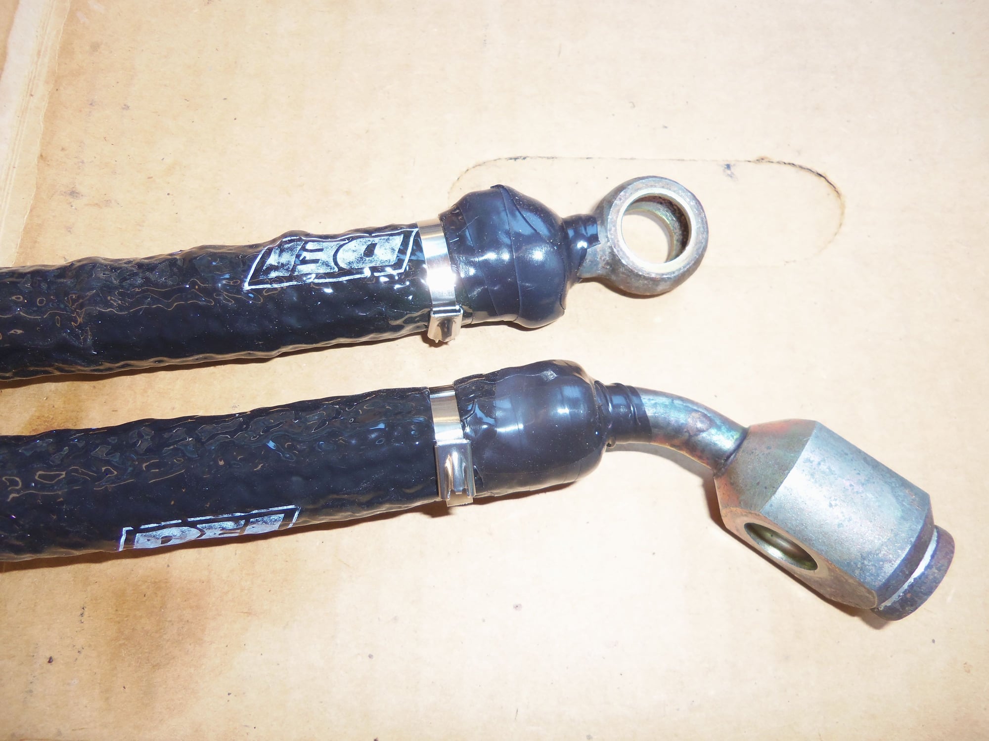
Painted and dried front transmission cooling lines.
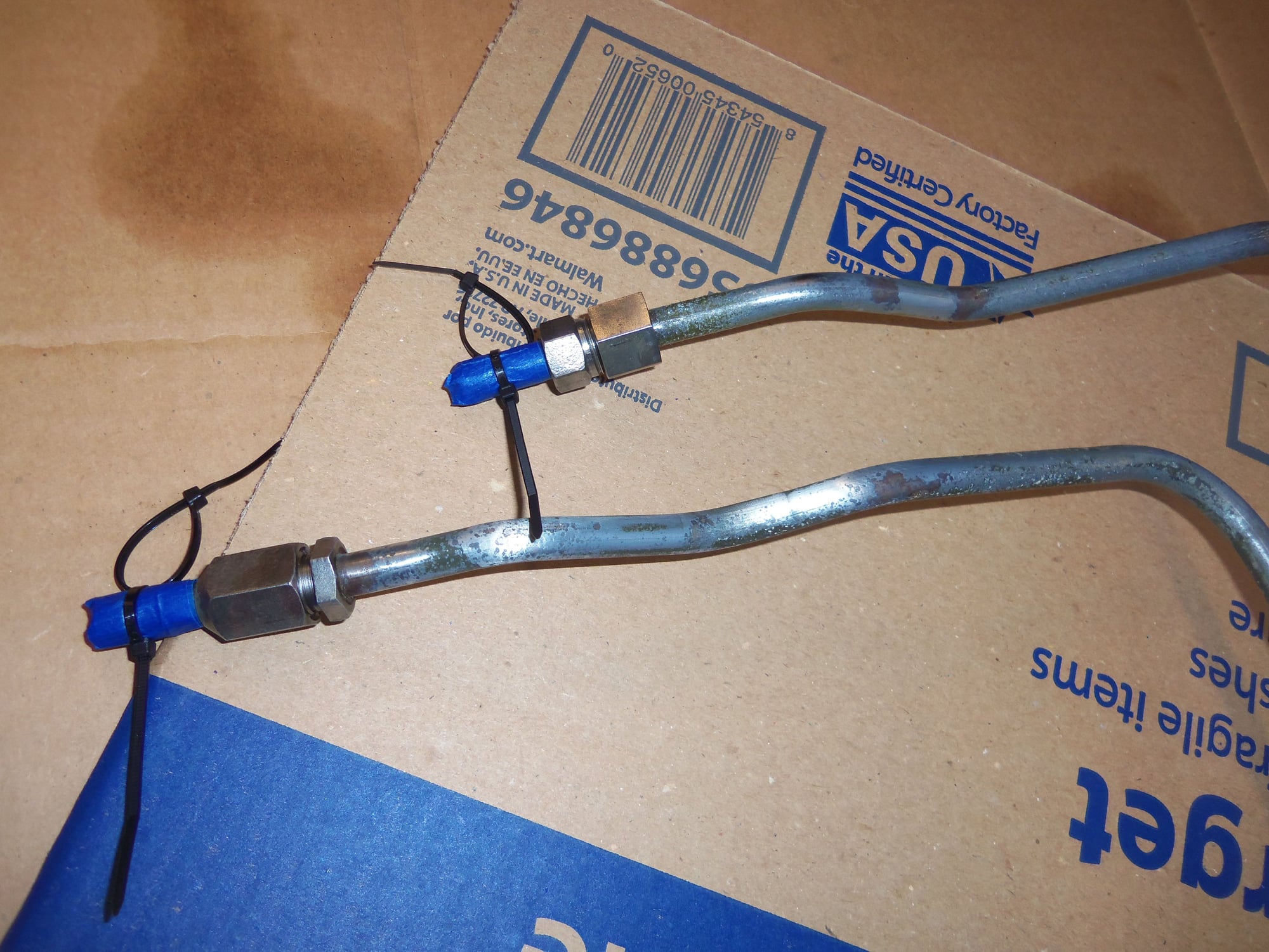
Unions painted, barbs clean.
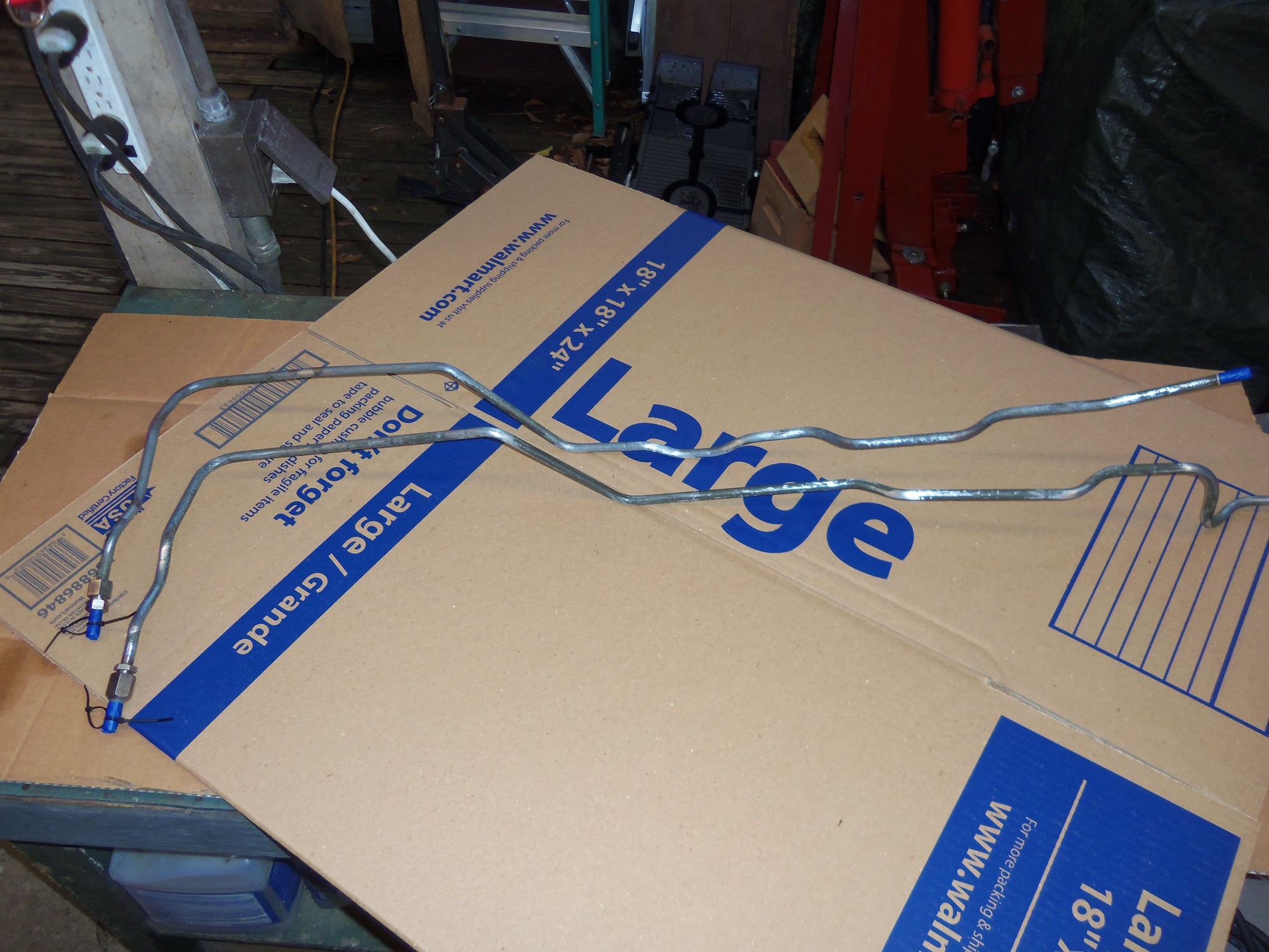
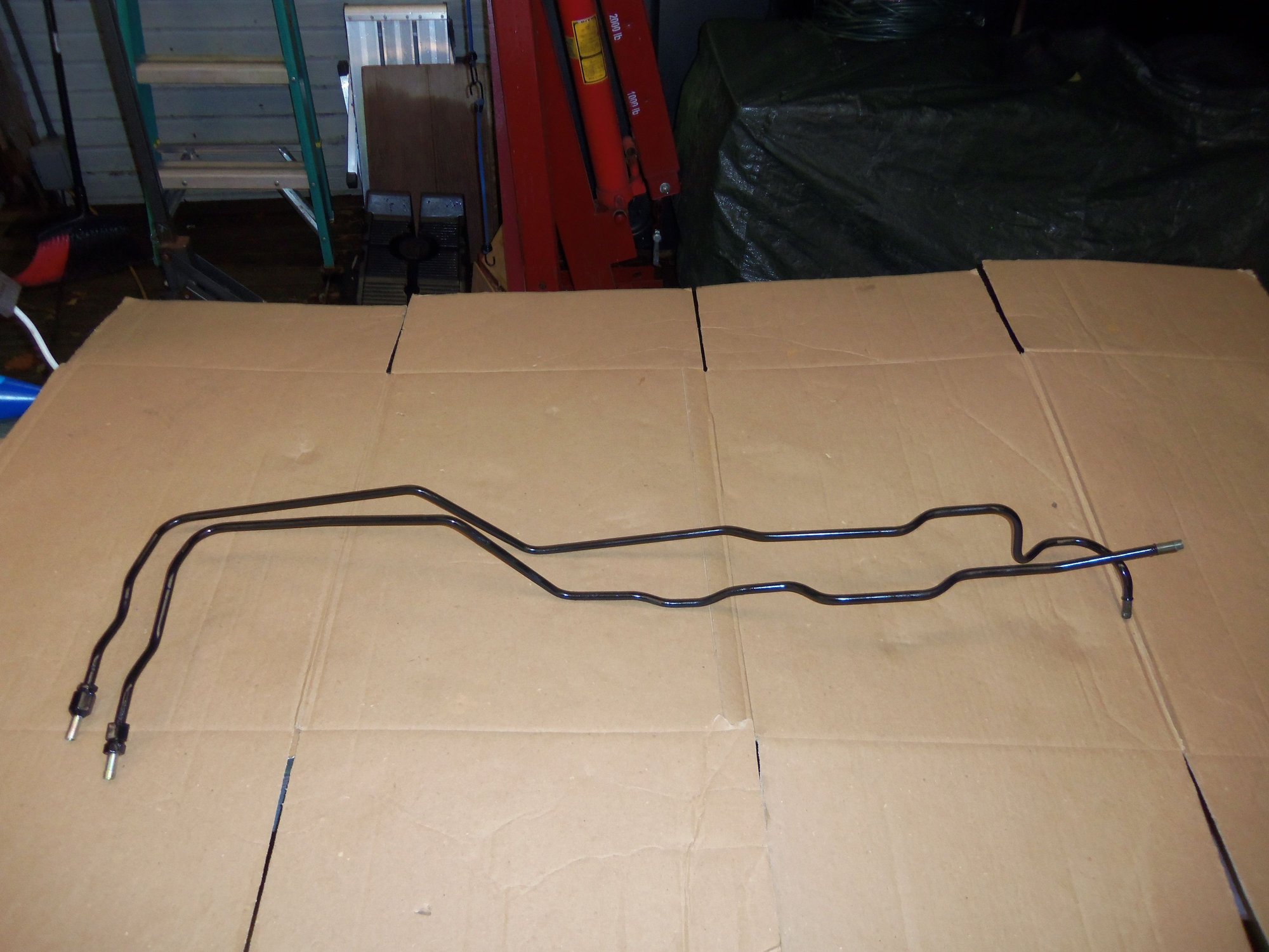
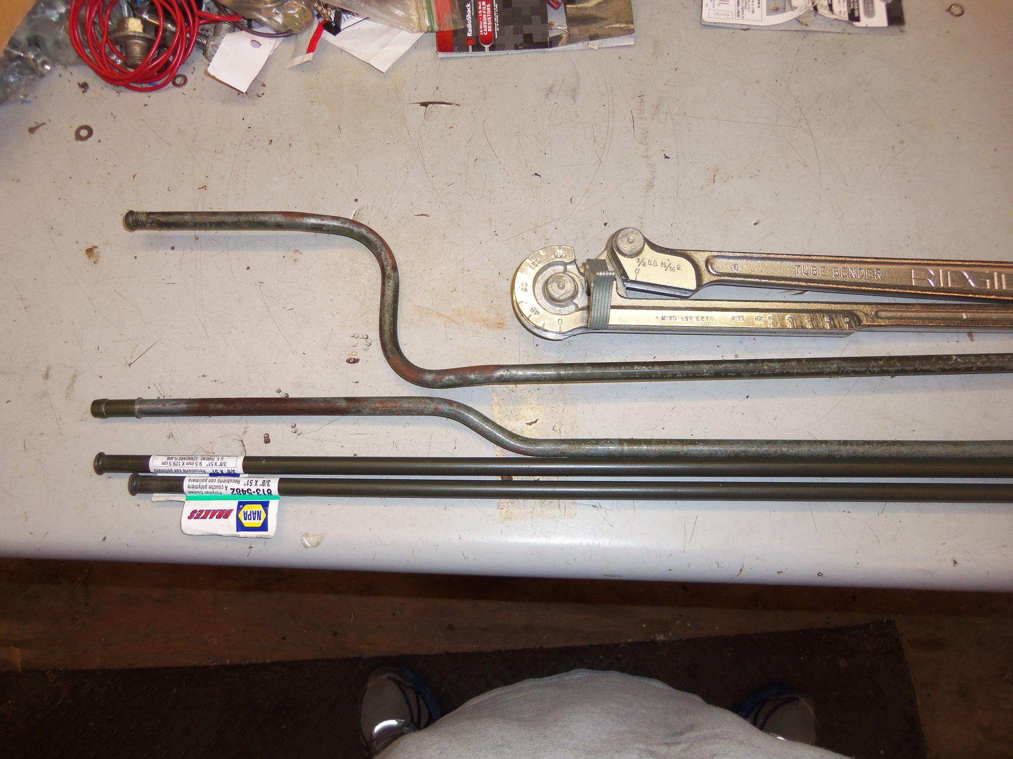
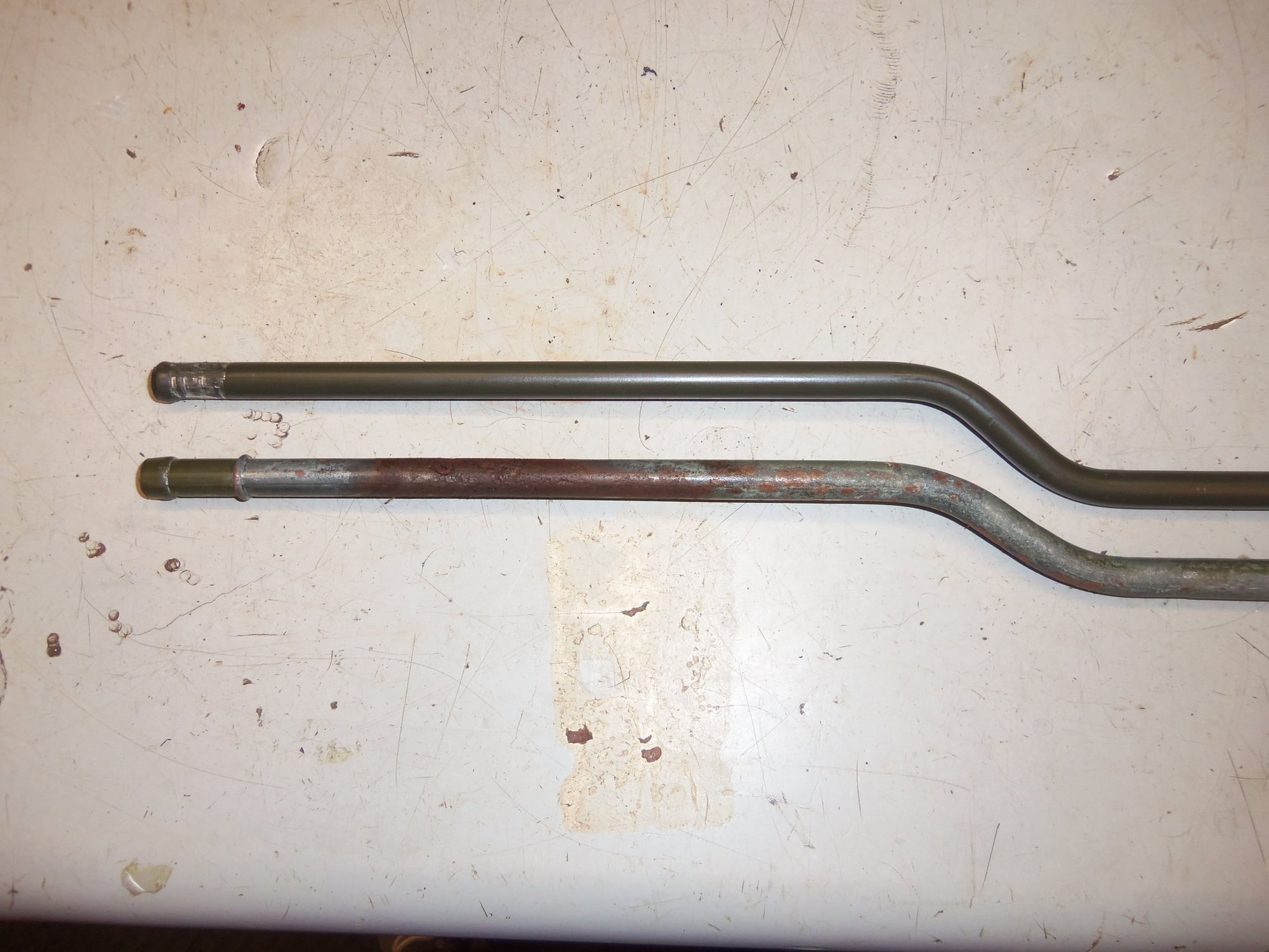
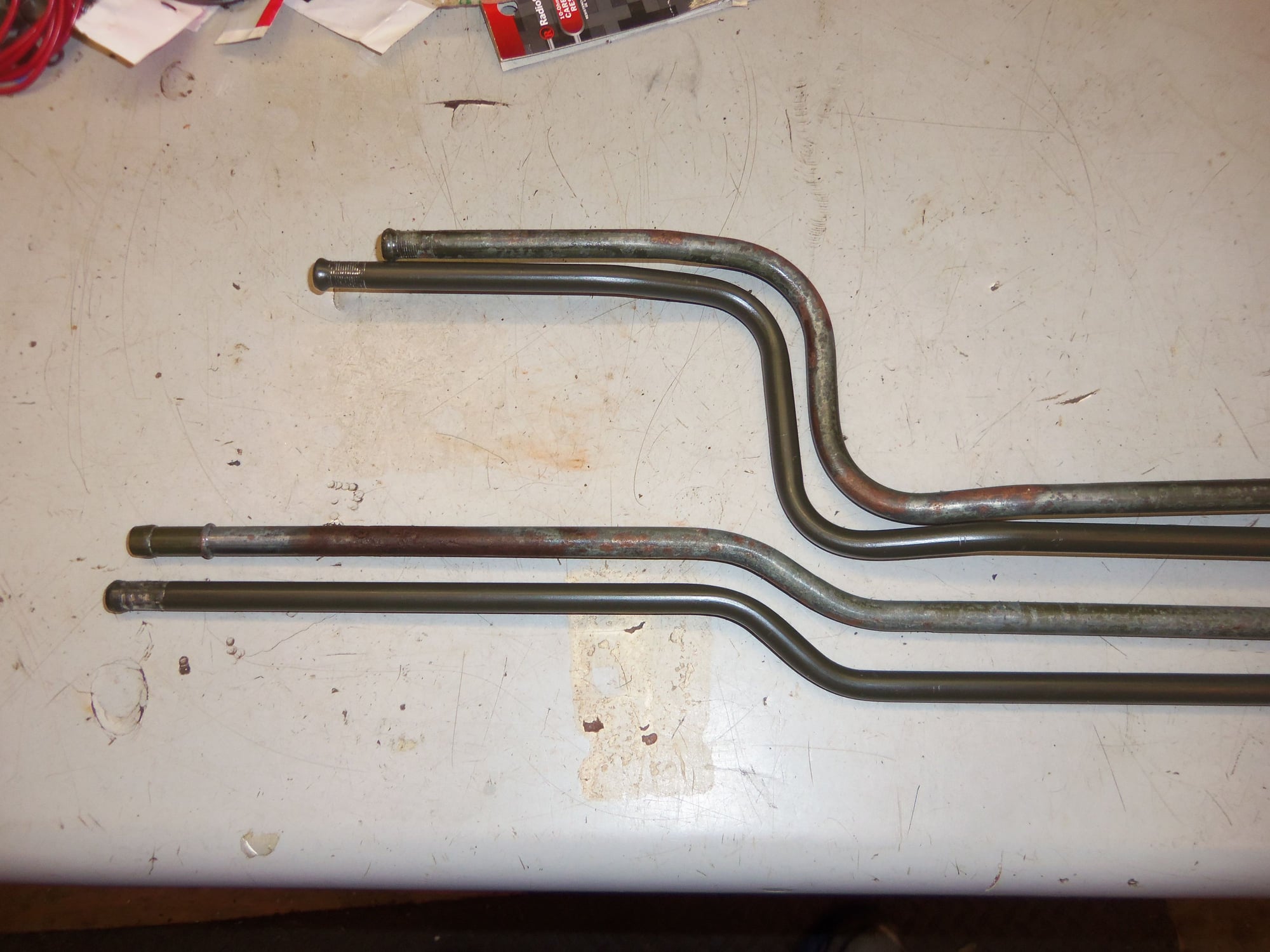
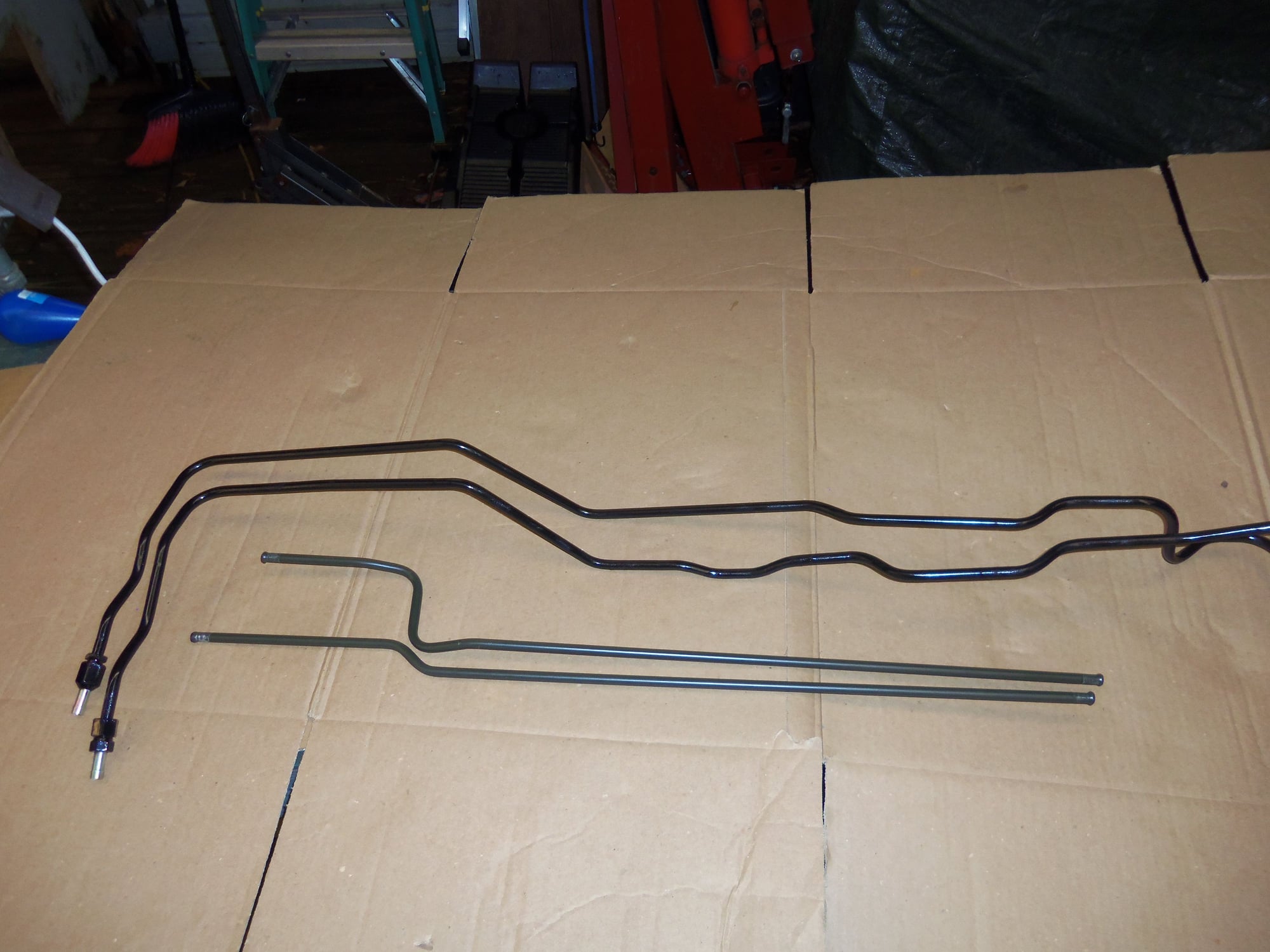
Today, I got out the tubing bender and double flaring kit, and went to war. I am capable of bending tubing, just not very good at it. This time, I was able to reasonably duplicate both rusted rear transmission cooling lines. I was able to match all the bends.
I did screw up and forget to add in the missing length of the tube that was shortened by Auto Assets, and then me. I don't really think it makes that big a difference. We are talking maybe 2-3" which can be made up for with a little extra hose.
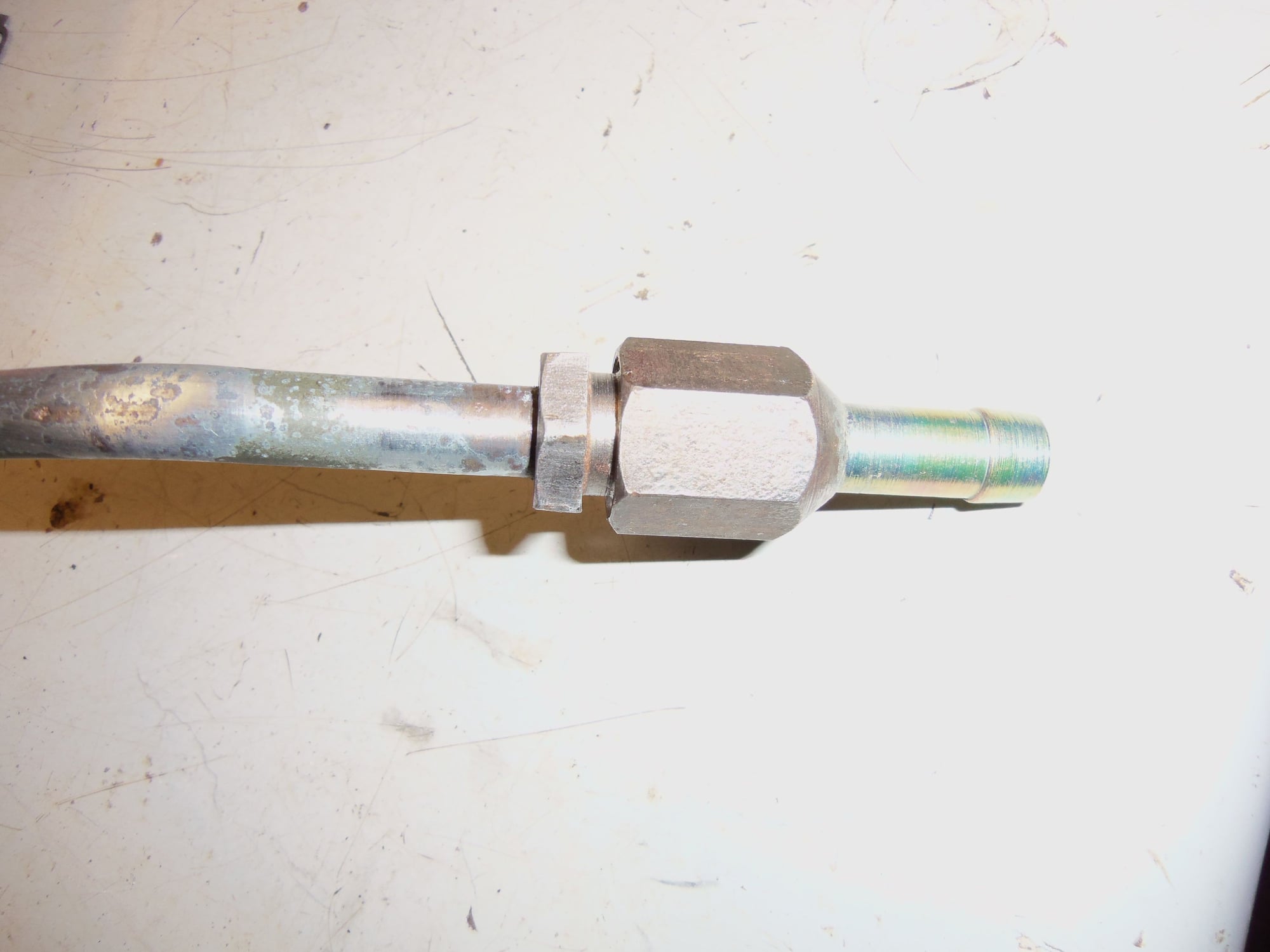
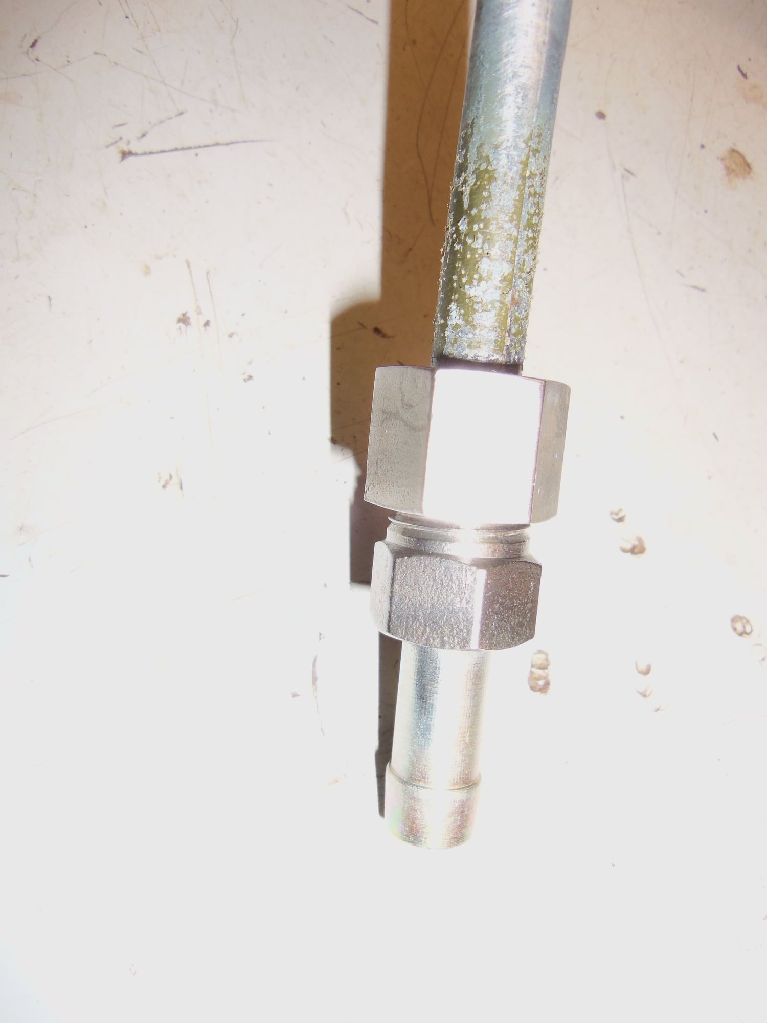
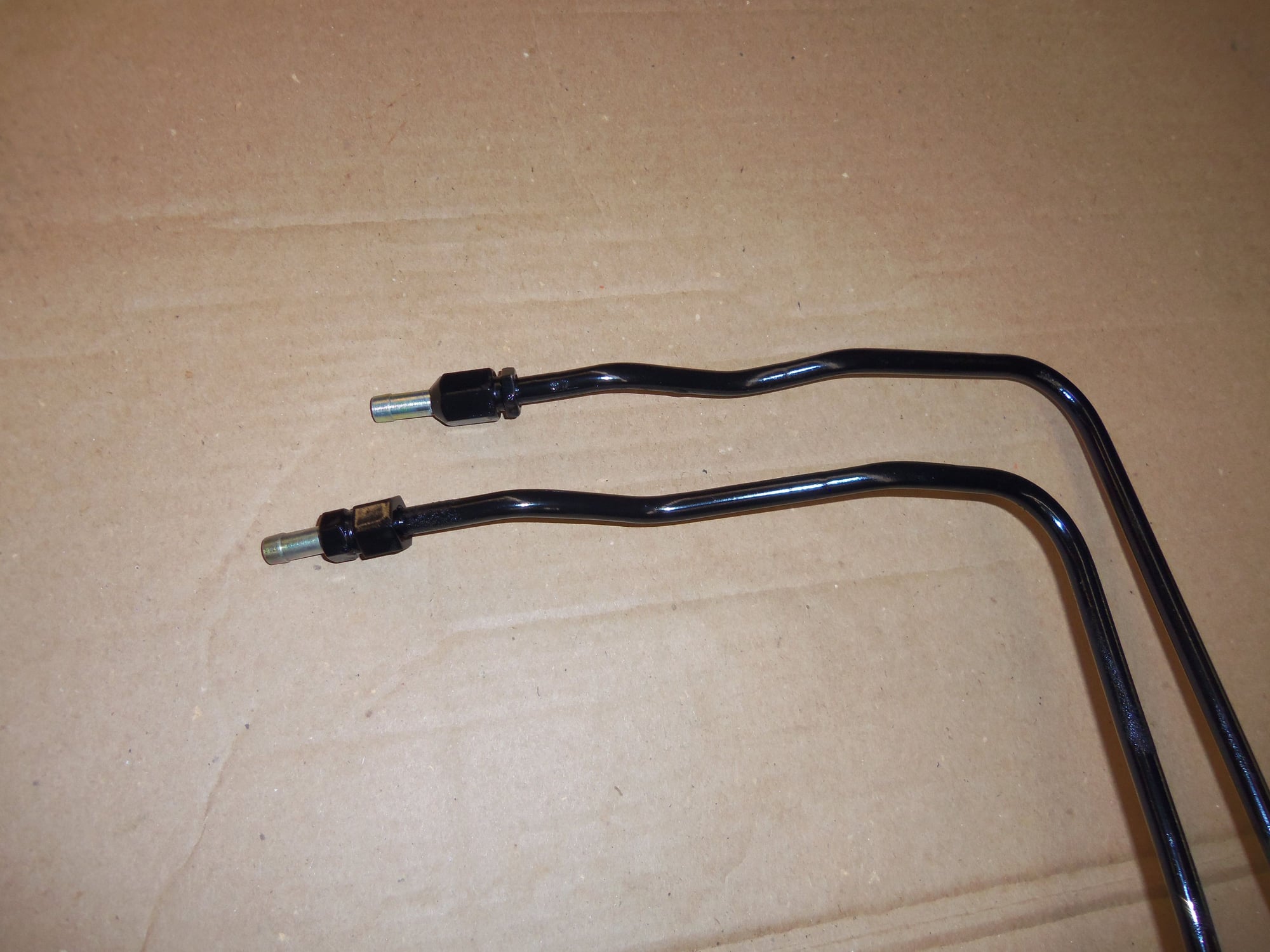
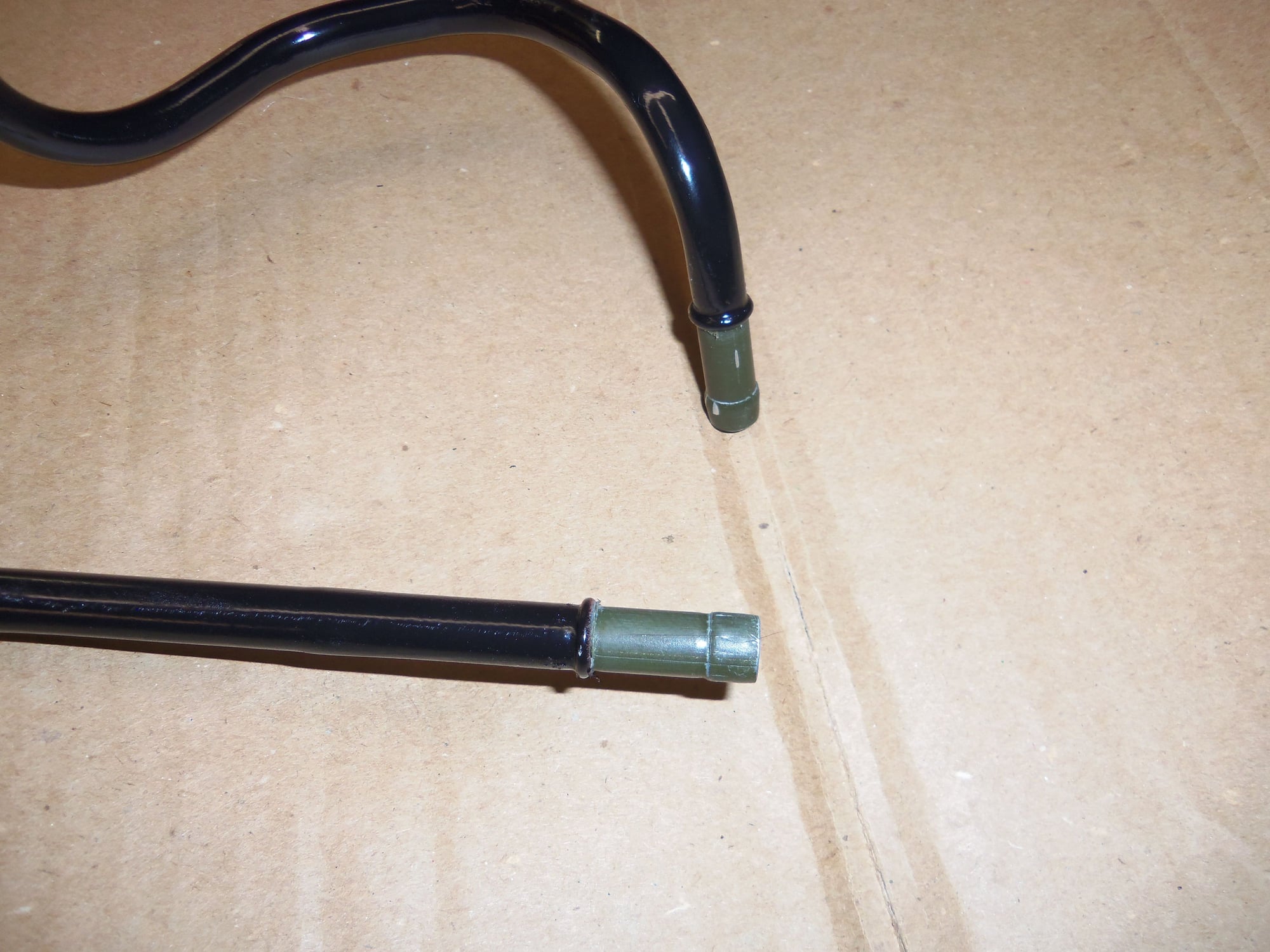
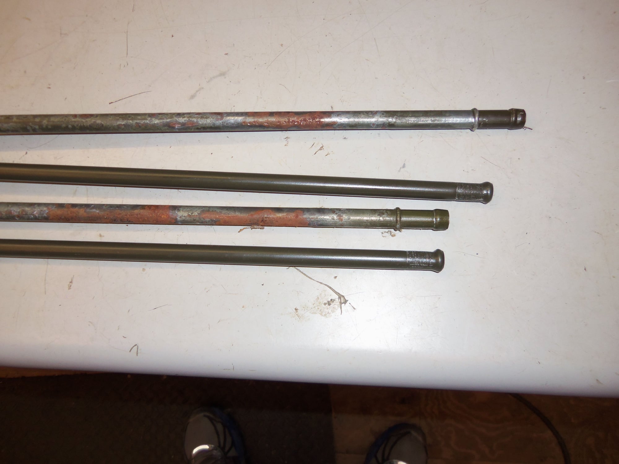
I put a bubble at the ends of each line for hose retention.
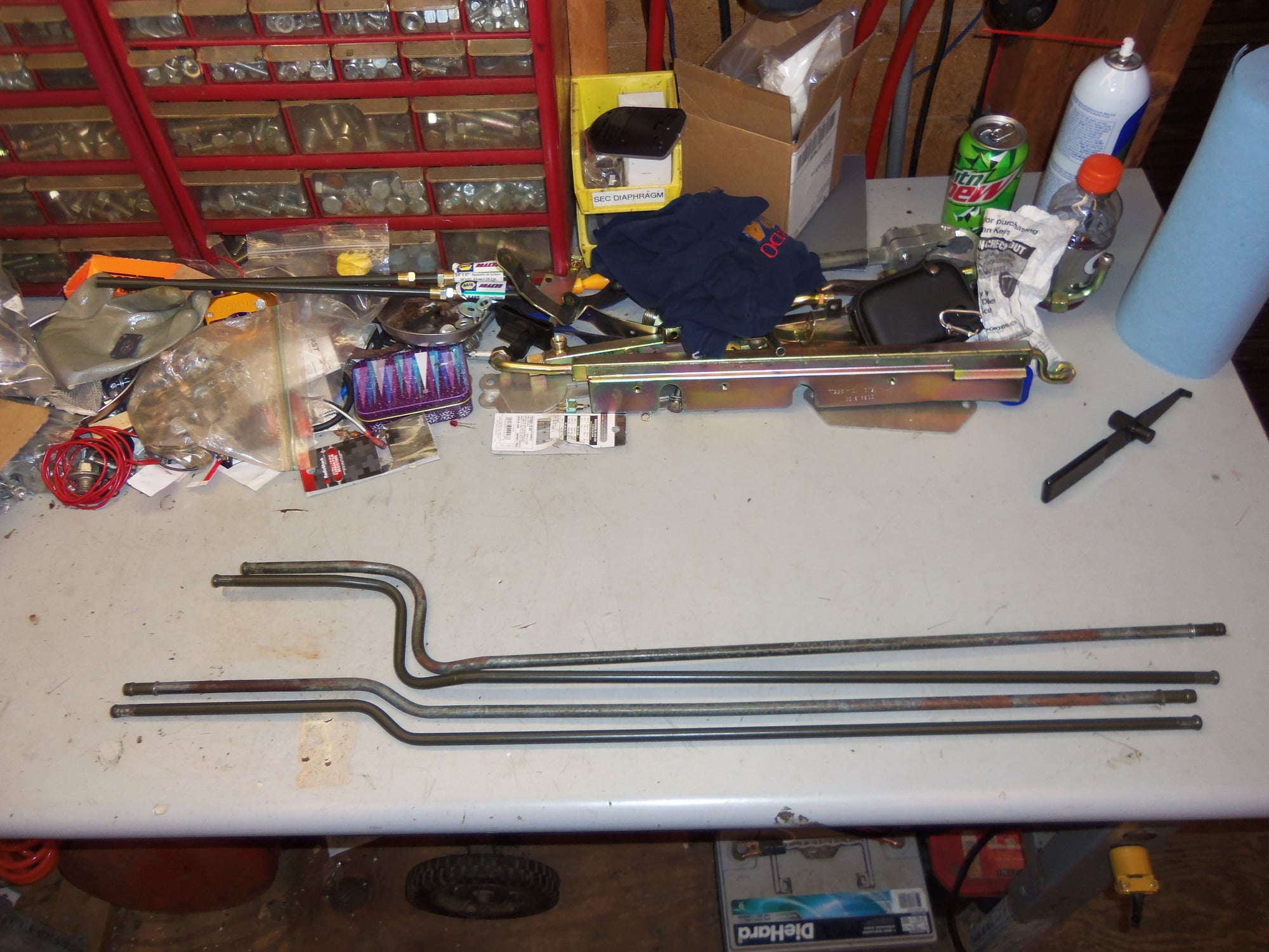
Tools of war and raw materials.
Even got the extra bends right.
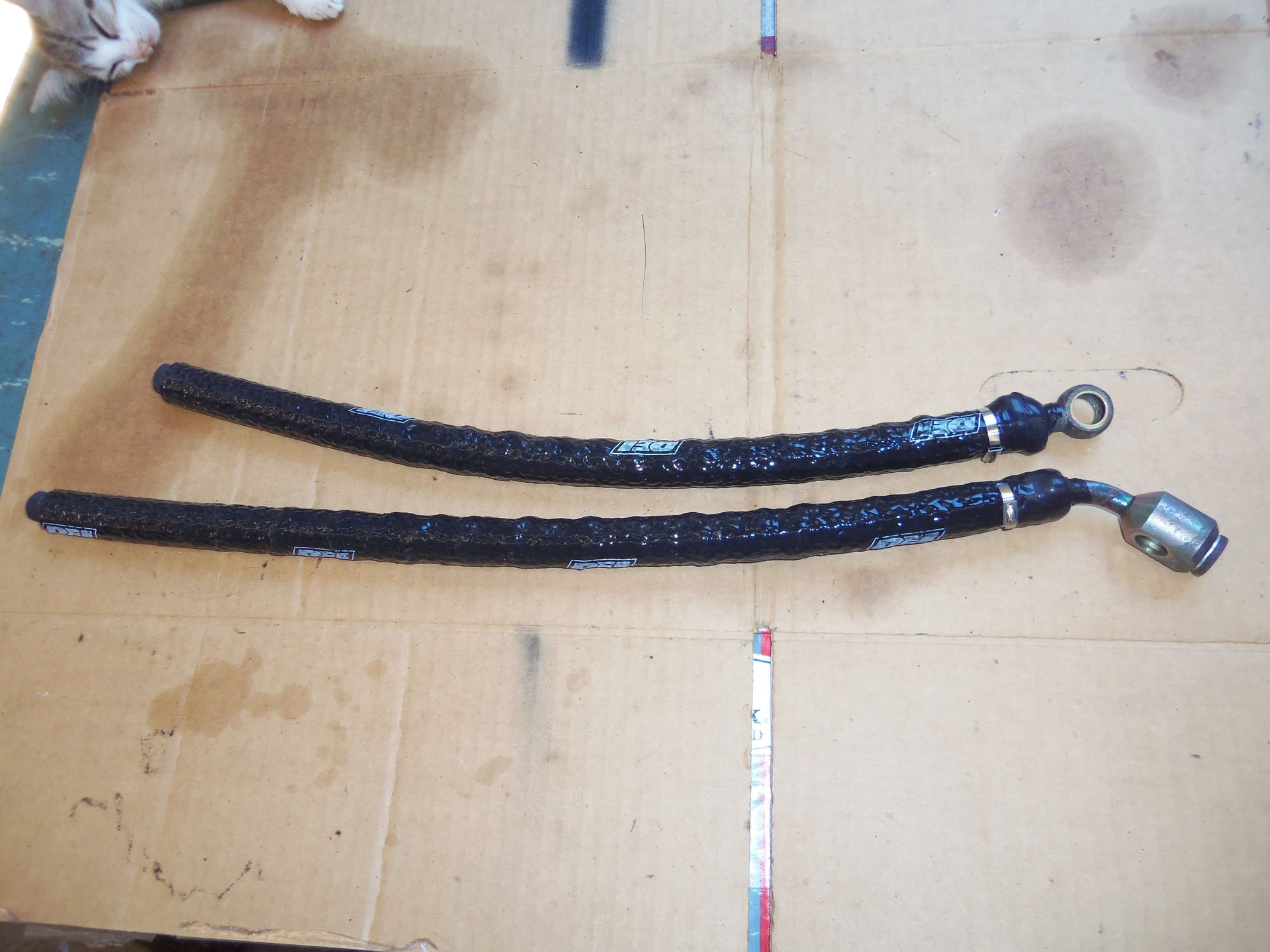
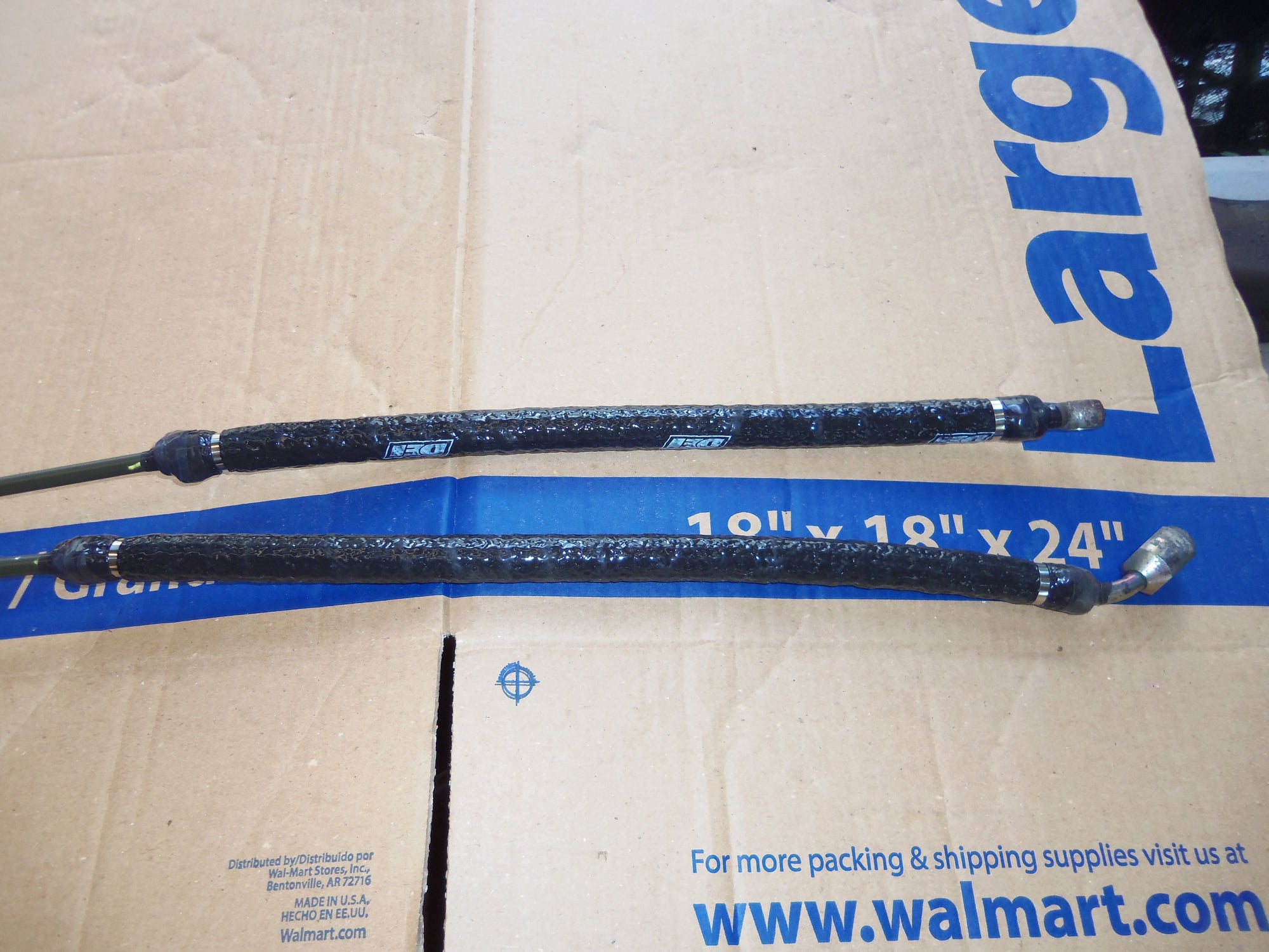
Front and rear transmission cooling lines, ready for reinstallation.
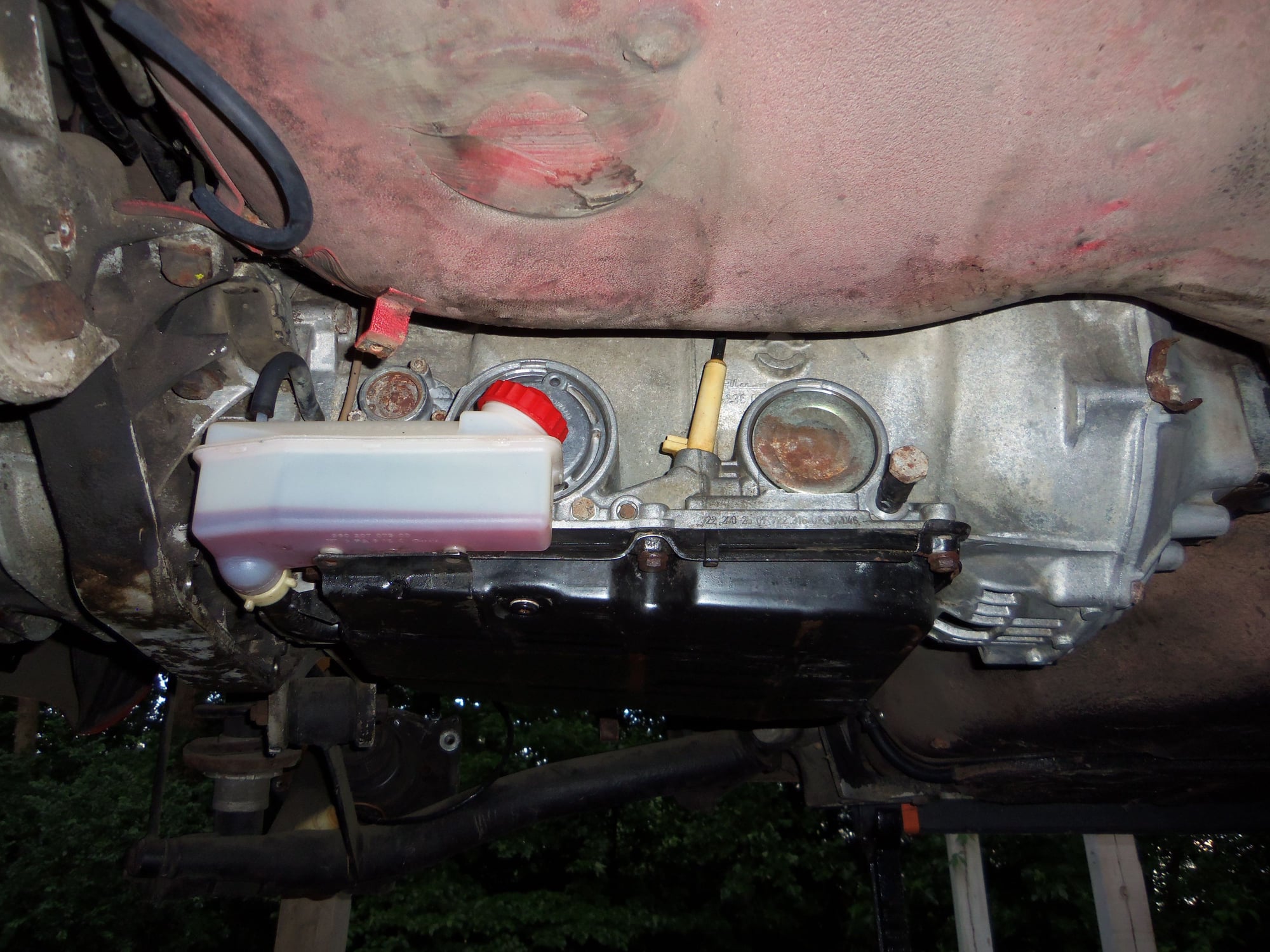
Before I install the lines, I wanted to clean the transmission casing.
Properly.
dr bob, this is what I should have done this time last year. I spent lots of quality time under the rear of the Red Witch with mineral spirits in a spray bottle and various brushes. Much better.
I scrubbed the sides of the transmission, as well as all of the torque converter housing that I could reach. I also wiped down the torque tube with mineral spirits on a rag.
Not perfect, as I could not get behind the plastic reservoir. I didn't feel like removing it. It will be alright.
I did plug the open line holes in the casing with the banjo bolts wrapped in E-tape. Ghetto, but it worked.
Much cleaner than the half-a$$ job I did last year.
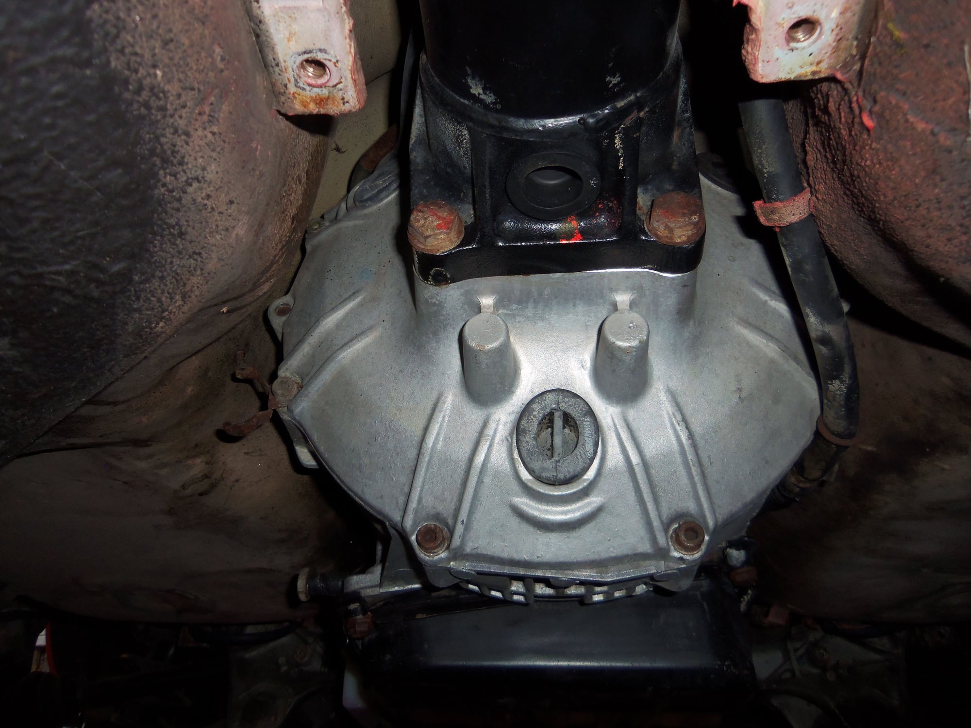
Note the new rubber plugs in the torque converter housing holes.
Not overly concerned with surface rust on the torque tube at this point in time. Down the road, when I rebuild the torque tube, I will deal with it.
Tomorrow, my plan is to loosely fit the metal transmission cooling lines in their plastic body clamps for proper positioning, then start fitting the hoses and clamps. Top it all off with firesleeve and we will call it good.
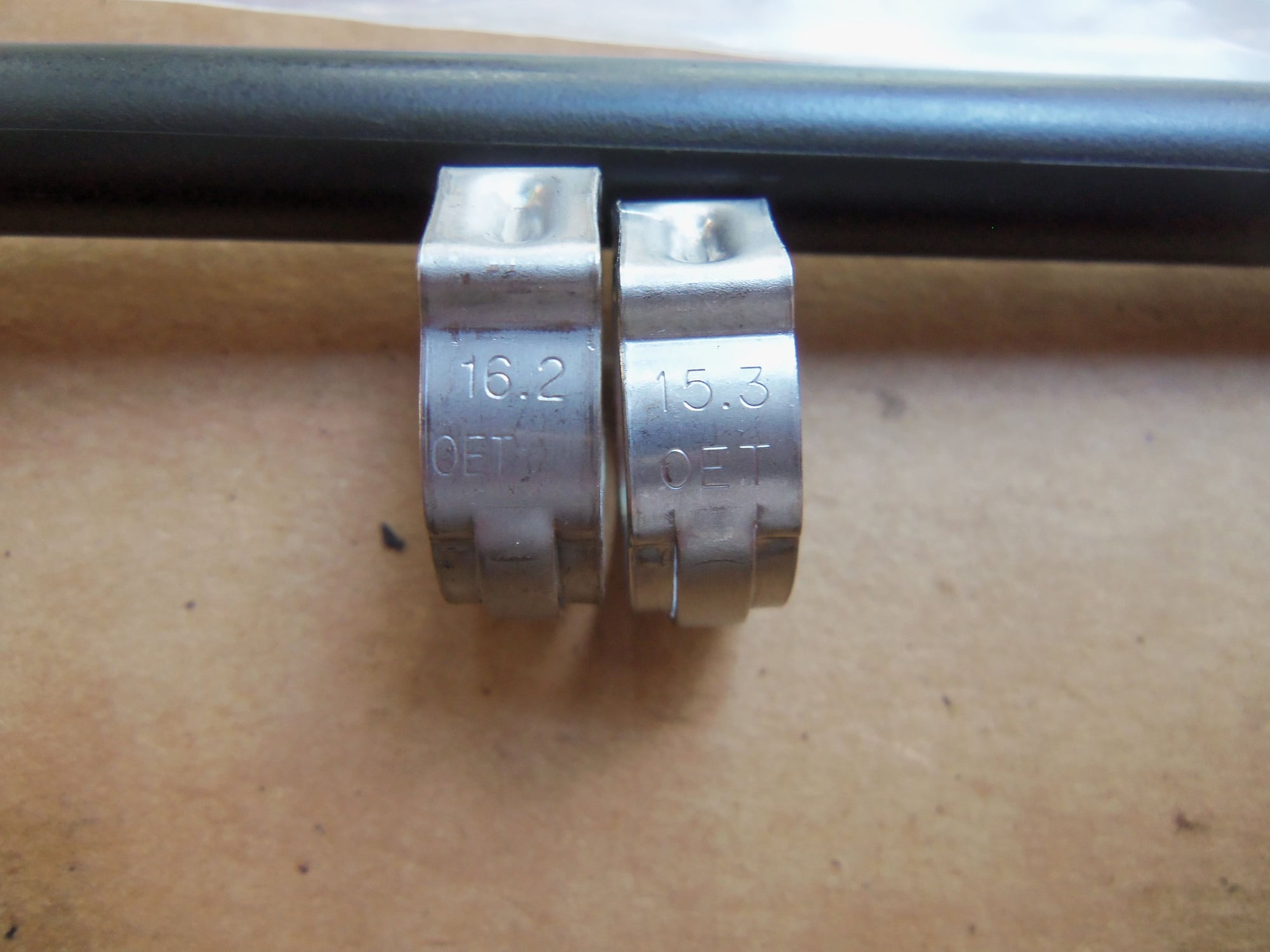
Started off by fitting hose to the banjo fittings for the connections at the sides of the transmission casing. I decided to use double clamps on each hose connection. Paranoia or due diligence, you decide. I used OET crimp clamps from Greg Brown. Anywhere the hose connected to the original Porsche lines or fittings, I used two OET 17 clamps. Anywhere the hose connected to the newly fabricated 3/8" lines, I used two OET 16.2 clamps.
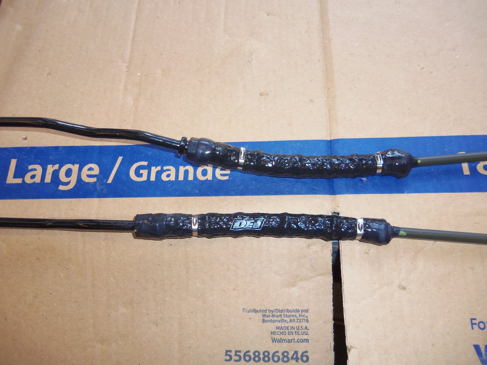
I was pleased to find out that the 5/8" DEI Firesleeve would expand enough to fit over the crimped OET clamps. I cut enough sleeve to cover the entire hose. I sealed each end with DEI Firetape (silicone self fusing tape), then a layer of my own silicone self fusing tape. I did this to prevent the sleeve from fraying over time.
I put a stainless steel zip tie at each end of the sleeve, before the clamped section. In my mind, this will help keep the sleeve from moving.
Side note, I bought Dorman brand zip ties. Reading the reviews, some people had issues with the locking part of the tie backing off a little. I figured I would deal with that as I went. I did. I used my CV boot clamp tensioner tool to pull the zip ties quite tight. That did the trick, none of them backed off.
Crimped hose, double clamps, firesleeve, firetape, and zip ties.
Note the tape up on the sealing surface of the upper banjo fitting.
Completed assemblies ready for test fitting.
Fixed it.
I completely crimped and finished the hoses at the banjo fittings. I loosely assembled them to the transmission casing using old crush washers for proper spacing. I then mounted all four metal transmission lines in their respective clamps on the torque tube and the body.
I then measured and cut the hose to fit each joint. Using yellow paint marker, I made alignment marks. Pulled it all back out and assembled everything on the workbench. Same as with the earlier hoses. Line up the alignment marks, double clamps, firesleeve, firetape, my tape, then zip ties.
I did have a couple of 'gotchas'.
On the second hose, I had a clamp that would not fit. As per Greg's instructions, I put two clamps on the metal line, then pushed the hose on. The clamps are so tight that they will not go over the hump in the hose from the barb or bubble on the metal line. One the clamps would not go up the hose no matter what I did. I got it to go onto the very end of the hose, but no further. After trying too long, I looked at the clamp. It was an OET 15.3. Oops, that one snuck in there on me.
Disassembled that joint, made sure I had two 16.2 clamps, and finished the joint.
On the first hose that was to be bent in a 90 degree, I cut the firesleeve too short. I didn't account for the added length from the bend. So, I now have an extra 7-1/2" long piece of firesleeve.
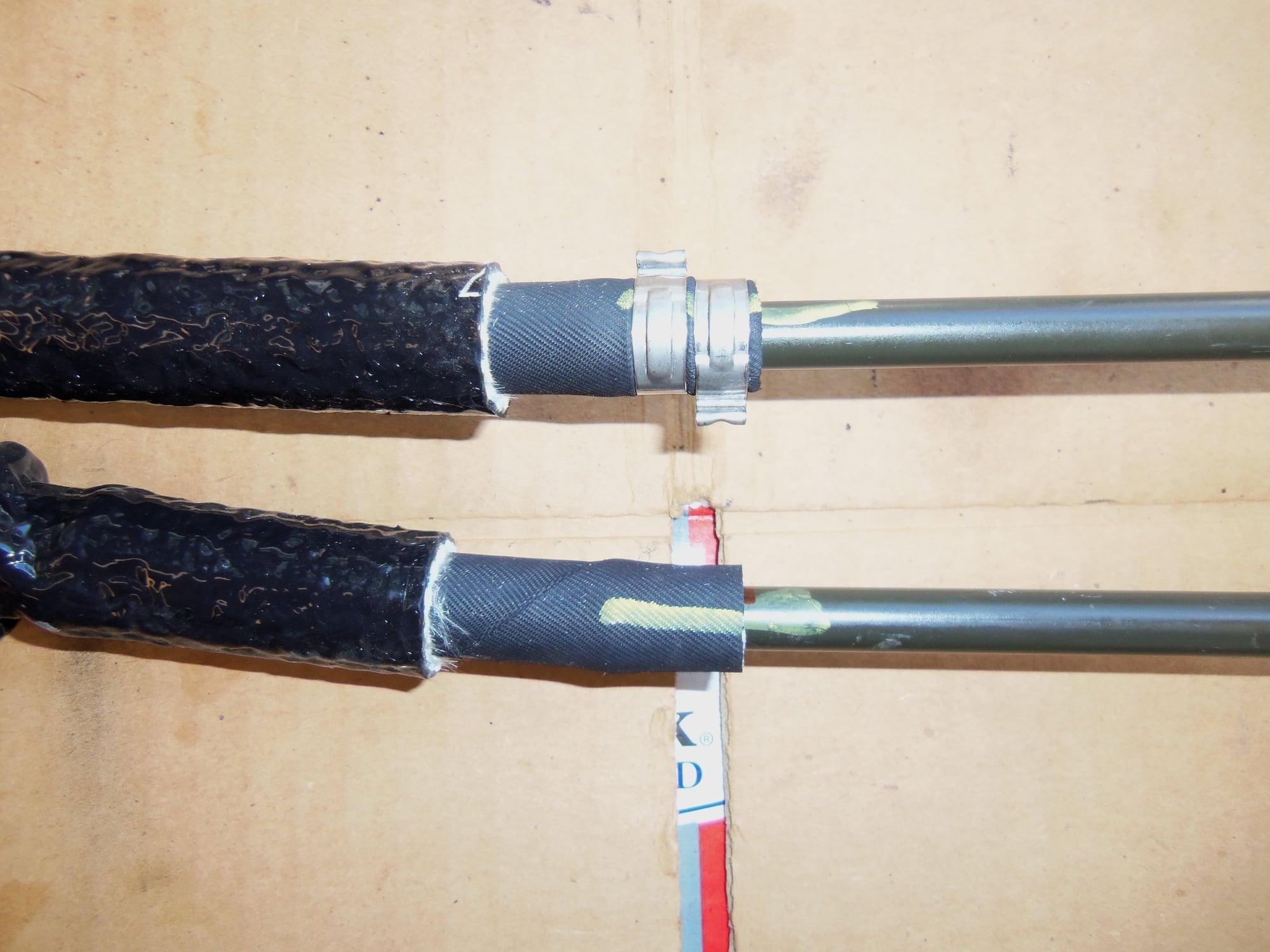
Crimps and alignment marks.
Correct OET 16.2 clamp and the whammy 15.3 clamp.
Transmission end hoses completed.
90 degree hoses at torque tube completed.
With the transmission lines assembled, I then worked at getting them into position. They were quite unwieldy to remove. They were worse to install. I ended up using the engine to frame ground strap and one of the long hose clamps around the torque tube as cradles to hold the lines.
One by one, I fitted the rubber inserts and plastic body clamps to properly locate the lines. Then, I loosely threaded the banjo bolts and fittings into the holes in the sides of the transmission casing.
Note: make sure the little check ball is in the proper place INSIDE the fill port fitting that goes on the passenger's side banjo bolt. I had the check ball sandwiched between the cap and the fill nipple so I wouldn't lose it. I forgot to put it back inside the fitting. That has to be done BEFORE the banjo bolt is passed through the fitting. Good to know.
With the body clamps tight and the banjo fittings loosely threaded in, I set the clamps on the torque tube. The metal lines are located by four plastic pedestals. Two two-slot, and two one-slot. These, and the lines, are in turn held in place by three large hose clamps. With some shimmying and wiggling, I got all the clamps, pedestals, and lines in the right place. Tightened the clamps and called it good.
I took a page out of dr bob's book and lightly coated all the new aluminum crush rings with teflon pipe dope at installation. I was unable to find any kind of torque spec in the WSM, the Porsche A28 specific manual, no in Rob Edward's excel file. I did find a value of 34 Nm on a PDF for the Mercedes 722.3. That converts to 25 ft/lbs. So, to take account for the pipe dope, I backed torque off to 22 ft/lbs.
I was able to properly torque the passenger's side banjo bolt, counter holding the fill port with a thin 7/8 wrench. The driver's side banjo bolt was too close to the body, so I gave it my best 'feel' with a 19mm offset box end wrench. Good enough.
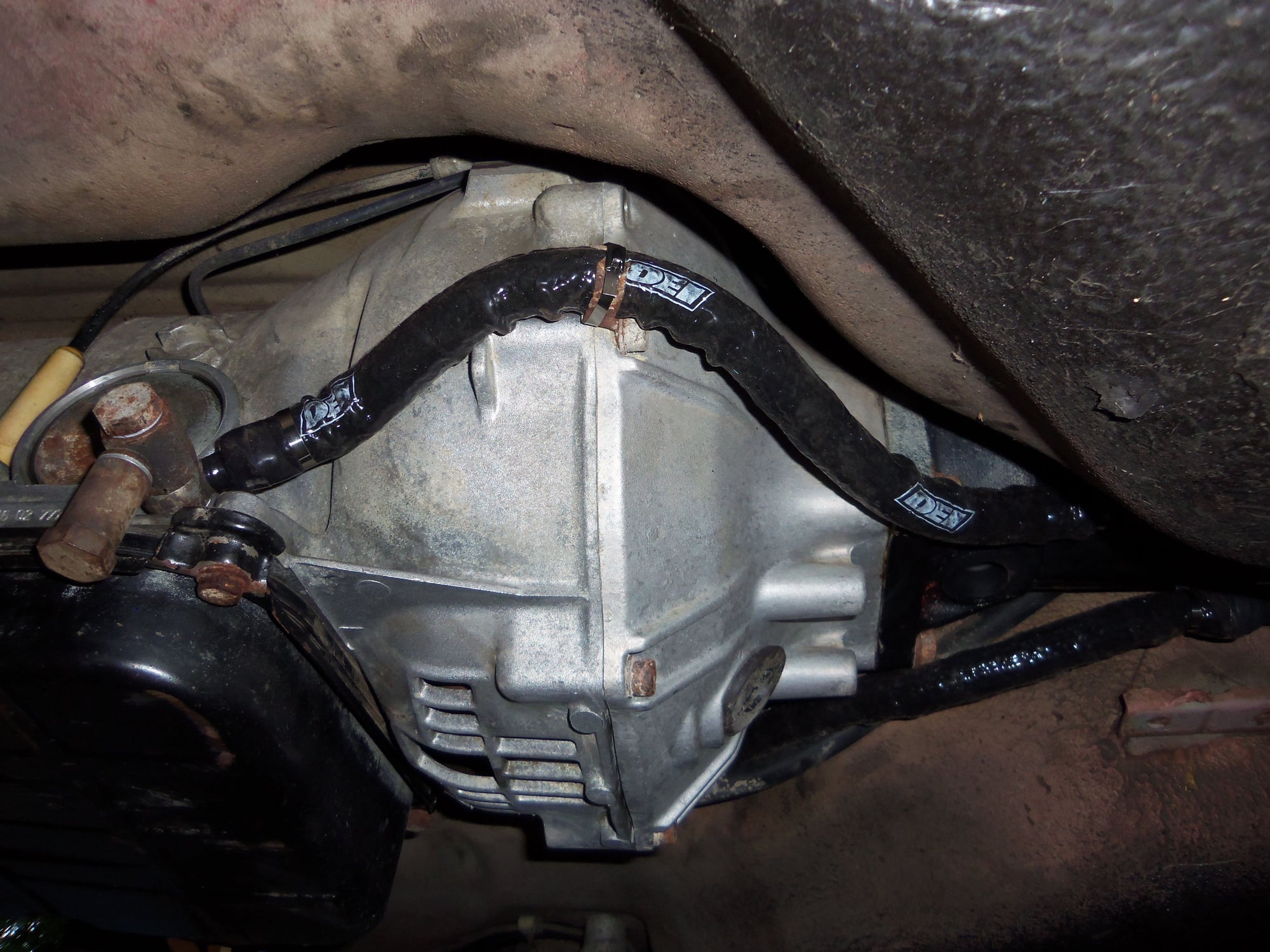
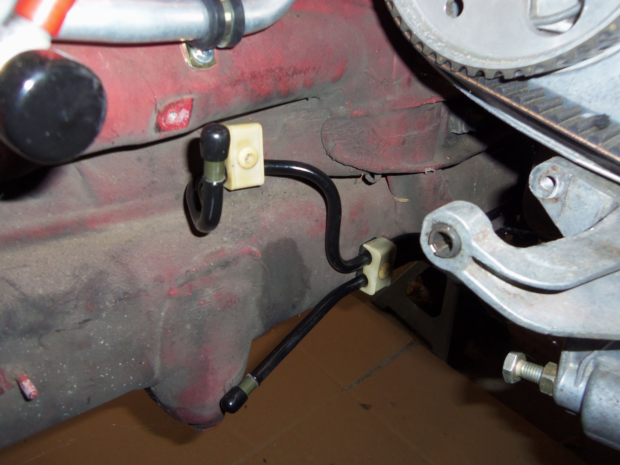
Passenger's side line at transmission. Note fill port, and note the stainless steel zip tie around the flimsy factory locating clamp on the torque converter housing.
Driver's side line at transmission.
Both lines meeting the metal lines at the torque tube.
90 degree hoses at the torque tube.
Shiny lines and clean body clamps.
Ends of the lines are capped off for now.
I did not do anything with the engine compartment end of the front metal transmission lines. I have not yet decided upon the hose routing for the remote oil filter I am adding to the transmission cooling circuit. I am considering placing the filter mount where the air pump filter housing used to be. Not sure yet. Either way, I will work that out in the future.
Next...finish installing the new rod bearings and finally install the oil pan!

 06-30-2017, 05:56 PM

 There is no SS anything, and my tubing choices are limited. Nothing metric. So, I am on my own.
 )
)


")