When you click on links to various merchants on this site and make a purchase, this can result in this site earning a commission. Affiliate programs and affiliations include, but are not limited to, the eBay Partner Network.
Before you go much farther you might consider replacing the rubber bulkhead that the A/C and heater hoses go through at the firewall. Now is an opportune time.
Mike
Mike, thank you! That is a very good idea.
Originally Posted by andy-gts
very nice job, why the difference silver vs copper anti seize, is this due to different metal surfaces...???
Hi Andy-GTS! You are correct, different anti-seize for different materials. I am supposed to be using the Porsche Optimoly copper and silver grades, but I am using these instead.
Copper is for ferrous to ferrous. In this instance, it was for the stainless steel screws into the steel rear keeper plate for mounting the expansion valve. Main reason is to prevent the stainless steel from microwelding itself to the steel. Bad juju.
Silver is for ferrous to alloy, usually aluminum. Since I had steel on brass, aluminum on brass, etc...I went with the silver.
Also, I put the antiseize onto the male threads, threaded the joint together, took it apart, then wiped off the excess antiseize. It does not need to be slathered on there. Just need a thin, even coat.
Originally Posted by Imo000
Well done. Just as a future reference to others, the regular wiper motor bearings are standard off the shelf items that any local bearing shop would have. They are about $10.
Very good point, sir! I went with the ceramic on a whim/dare. A good, easily sourced steel replacement ball bearing would have worked just fine.
Originally Posted by Jerry Feather
Nice write-up, Seth. Now, what are you going to cover it all up with?
Jerry, if you have to ask...
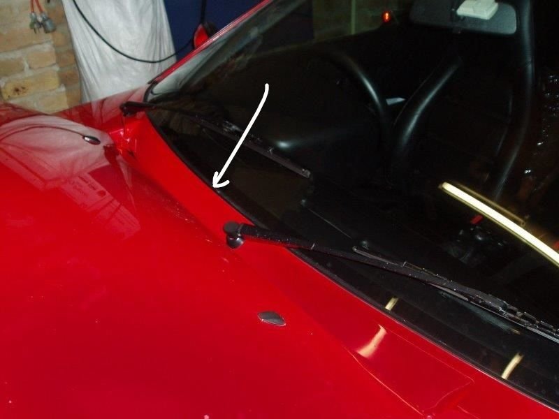
Here is what I am working with: OEM cowl cover, in all its too-thin-now-cracked-and-broken glory.
OEM cowl cover.
Note missing sticker and chunk of plastic towards the back.
This month's 928 budget has been shot to h*ll. So, next month, I am going to order one of your sweet cowl covers, seals, and appropriate stickers.
As for the rest of you, thank you so much for your kind words. This is my hobby, and the Red Witch is my passion. I know my place as a low class blue collar dirt ball, but I am determined to take care of my 928 right.
I have run my mouth before about 'doing my own work' and blah-blah-blah. These posts are proof. I am doing my own work. It my seem haphazard and scatterbrained. Because it is. But, I am following my own internal pattern. It will all get done in due time.
As well, these posts and photos are a way to sort of give back to the Rennlist 928 community. If someone can read my posts, and see that it can be done at home with the right tools, parts, and effort, and then THEY DO IT!, then I am good.
I have not installed the wiper arms, because I want to run the motor through a few cycles and then get it to park. Then install the arms.
This is a very good idea, you do _not_ want to install wiper arms until you are 110% sure the short lever on the motor shaft is clocked correctly and the arms are rotating as they're supposed to. We did not do that, and it wasn't pretty. Ask William how I know.
Start with strips of tape on top of the shafts as indicators, and watch them turn.
I didn't post that much about the wiper motor because I am a bit ashamed of it. It was a horror show inside, and I had to do a couple of questionable things to make it work. Well, for the sake of transparency, here is what I did:
Other posts regarding the wiper motor mentioned pushing on the rubber isolators that mount the brush plate to the gear casing. Yeah. Mine were rock hard and broke. So, I just broke them off and removed the armature and brush plate.
With everything apart, I actually wasn't sure if I was going to be able to make it run again, the corrosion was that bad. The closer I looked, the better the brush plate looked. It had corrosion, but none of it was in the wiring coils. The brushes had good length and the pigtails were not damaged. All four brush springs were still present and had not corroded through. The ground screw and grounding braid were pretty rough looking, but I figured I might be able to clean them up.
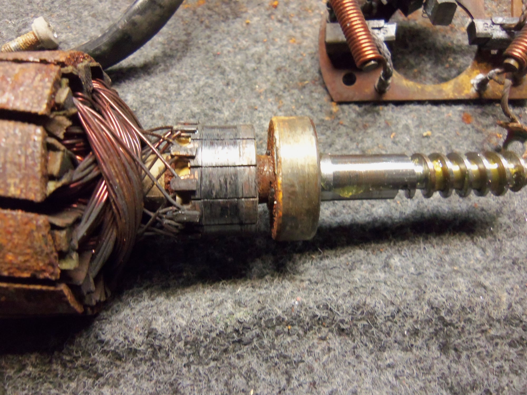
The rust on the armature was pretty heavy on the laminations, but not down into the actual windings. Luckily, there was no corrosion on the bearing/bushing surfaces on the armature shaft, and the worm threads looked good.
I was pleasantly surprised to find the grease to not be dried out and caked. There was grease on the various thrust washers and the shaft of the main gear. There was no damage at all to the plastic teeth on the gear.
The motor casing and gear housing went into the heated parts washer at work for a bath. Gear casing cleaned right up. Motor casing did not, but I really didn't expect it to. Those permanent magnet field pieces really held onto the rust. Luckily the bushing at the bottom was still in good condition.
I cleaned the inside of the motor casing as best as I could with lots of aerosol contact cleaner and a brass wire brush. It got most of the big chunks and dead chickens out. As bad as it all looked, it was functional. None of the magnets were cracked or damaged. The magnet retaining brackets were still structurally sound. None of the rust impeded the rotation of the armature. It was all just fugly.
The failed roller bearing came off the armature shaft with little drama. I have a good little puller for such things. I protected the end of the worm screw with a brass nut of approximately the same size. And remembered to remove the little circlip that locks the bearing to the shaft.
The armature went into a lathe at low speed and I worked the outer surface of the laminations with various wire brushes, scotchbrite pads, and finally 100 grit sandpaper. I knew I was never going to get rid of all the corrosion, I just wanted to knock it down to the surface of the laminations. I cleaned the commutator with red scotchbrite. It did not clean up perfect, but was functional. And, better than it was.
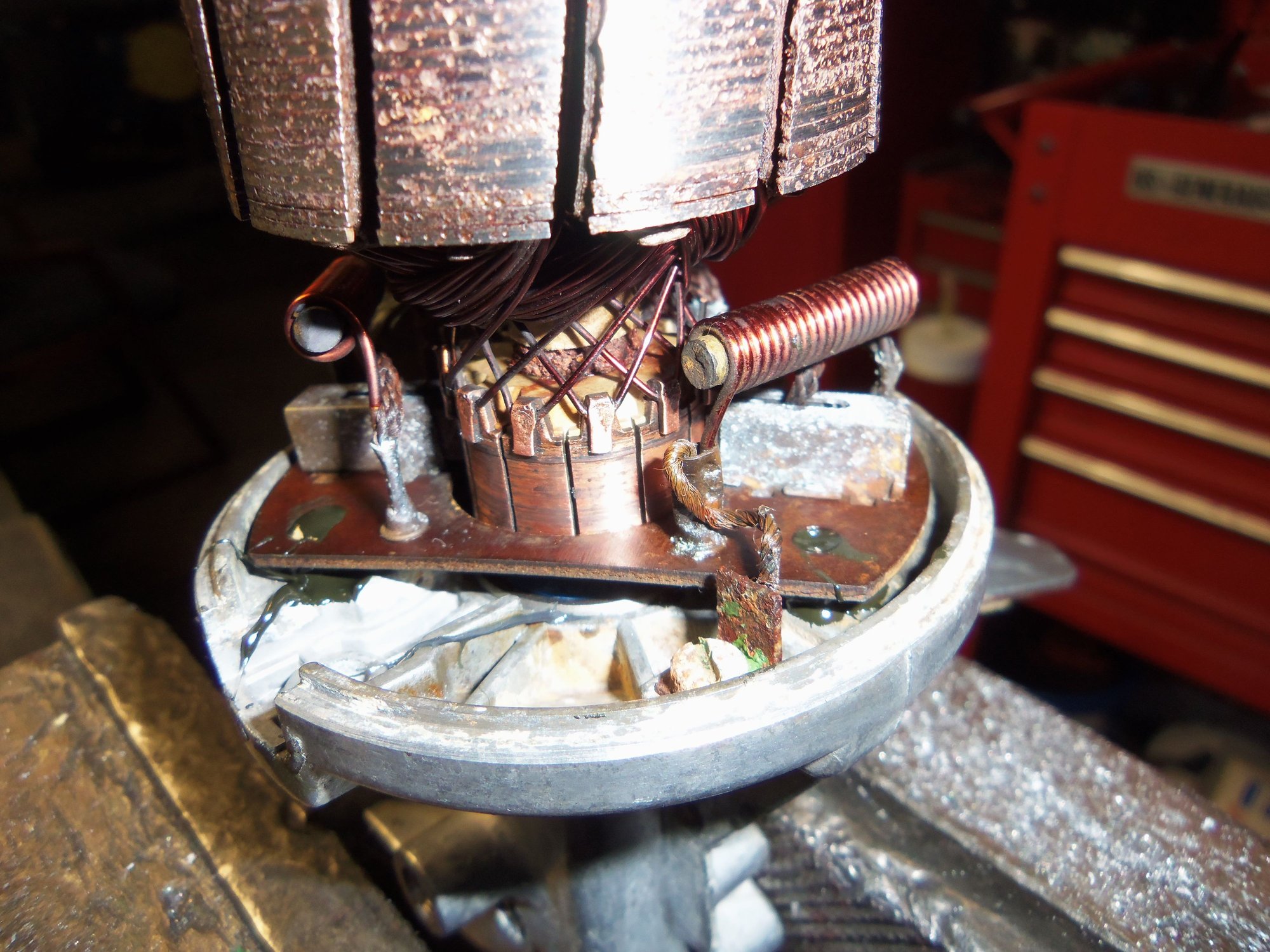
The brush plate and motor wiring got thoroughly drowned in aerosol contact cleaner. All the brushes had an acceptable wear surface wear they rode on the commutator, and slid freely in their holders. The ground braid didn't really clean up, so I killed it with DeOxit D100. It bubbled and fizzed. Much better. I also disassembled the wiring plug and cleaned the pins with DeOxit D5. The pins looked good, with no corrosion.
After pressing the new ceramic bearing onto the armature shaft and securing it with the tiny circlip(which I had to go search for once), I jigged up the gear casing in a vise. As I mentioned, I used the old bearing as a spacer to hold the brushes out of the way as I refitted the brush plate around the commutator. I then installed the armature shaft and brush plate on to the gear casing.
Here is where it got sketchy. Remember the rock hard insulators that broke earlier! They are needed because they correctly locate the brush plate in relation to the gear casing and the armature. Well...I glued the broken pieces back together with Permatex non-hardening sealant. And, I pretty much glued the brush plate in place on the gear casing with that sealant. The jigging of the gear casing in the vise was to orient the brush plate so it sat on top of the glued together mounts. To give it all a fighting chance to actually adhere and locate the brush plate in the right place.
It worked! The armature was able to rotate with no interference from the brush plate. I had a buddy hold the armature worm shaft in place in the gear casing with a large flat head screwdriver. I then quickly put the motor casing on, so as not to let the field magnets pull the armature shaft and brush plate out of the gear casing. That worked on the first try.
As for the horrible rust inside the motor casing, well... I sprayed it all down with a good coating of CRC 3-36 aerosol lubricant and anticorrosion spray. I coated everything, then turned it over to drip dray for a day or so. This let all the excess run out and left a coating on all the metal. I wiped the spray off the faces of the field magnets with a contact cleaner soaked rag. Topped it off with a screwdriver's blade worth of CV axle grease in the end bushing. Ghetto, but I think it will work.
After bolting the retaining keepers into place, I lubricated the inside of the gear casing with CV axle grease. Same thing with the gear, shaft, and thrust washers. Installed the cover plate and I now had a complete, though questionable wiper motor. How to test it? Randomly connect wires to a battery? Sure, let the smoke out after all that work.
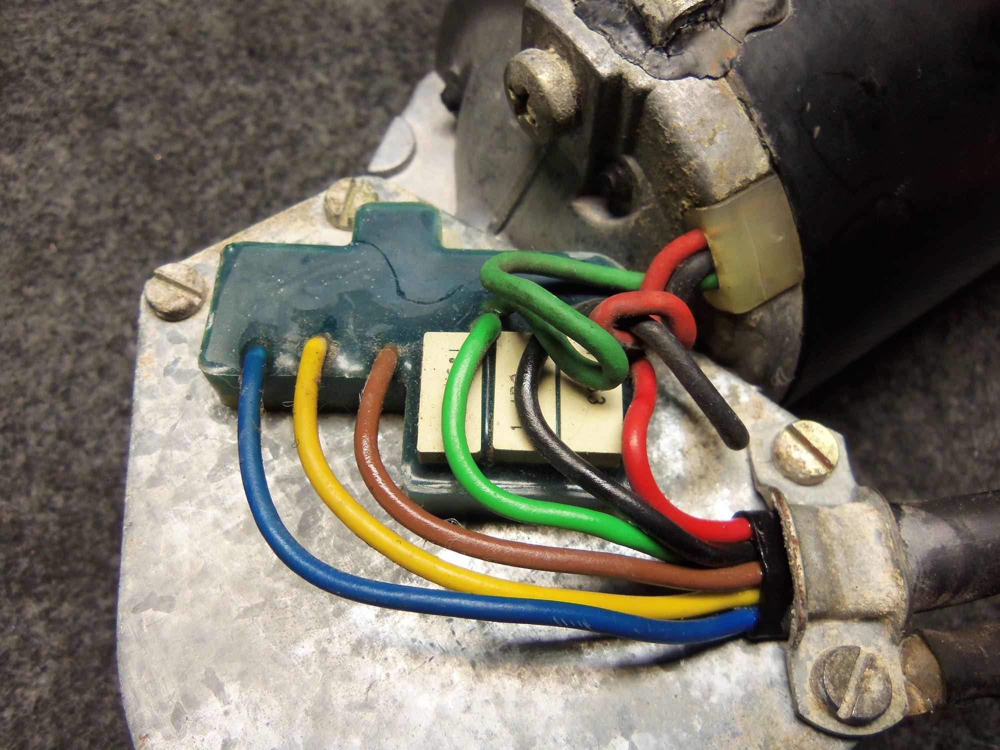
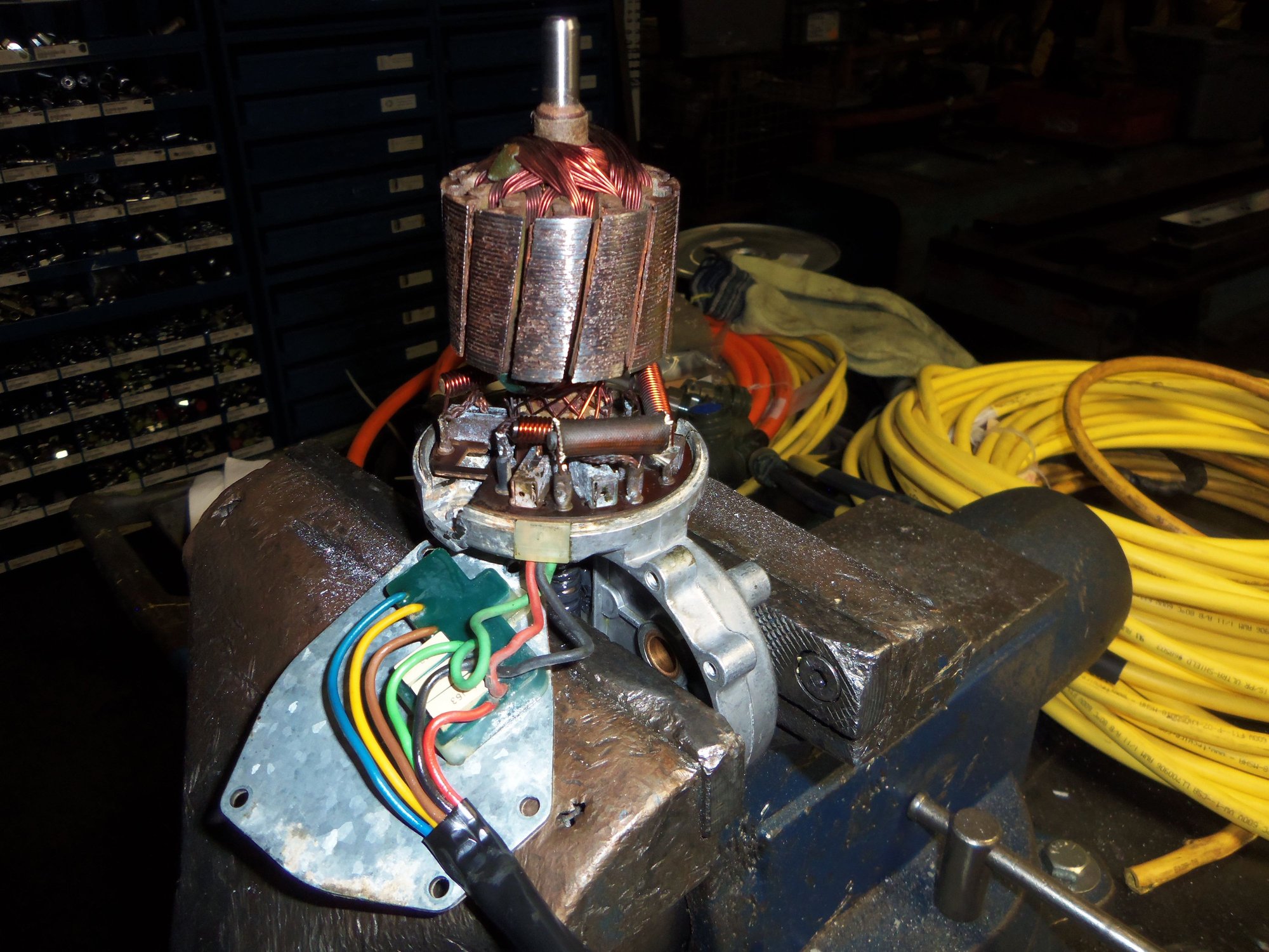
I dug through the wiring diagram, focusing on the switch assembly. I was able to figure out that the brown wire is the motor ground, and the yellow wire was one of the motor speed wires. Good enough. So, I connected the yellow wire terminal to the (+) of a handy jump pack, and touched the brown wire terminal to the (-) on the jump pack. The motor jerked and the gear output shaft turned a bit. No smoke. Yay!
I then held the brown wired onto the jump pack (-). The motor ran and the gear output shaft turned. It was smooth and quiet.
Very good!
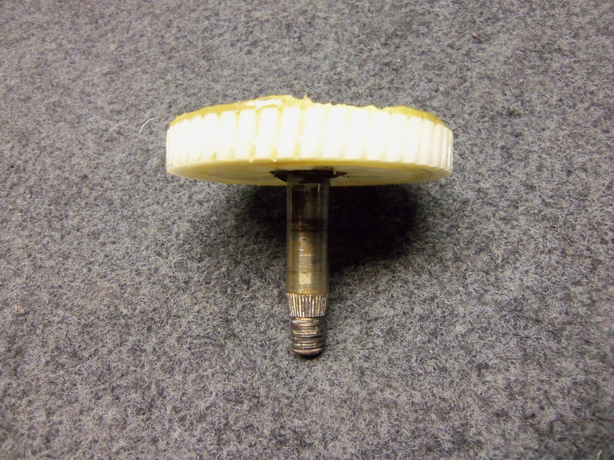
I will test all the speeds and the park function once the car is put back in a condition where the electrical system can be powered up. The delay function has never worked for me, I am going to assume the delay resistor wheel. I will troubleshoot that at some point...
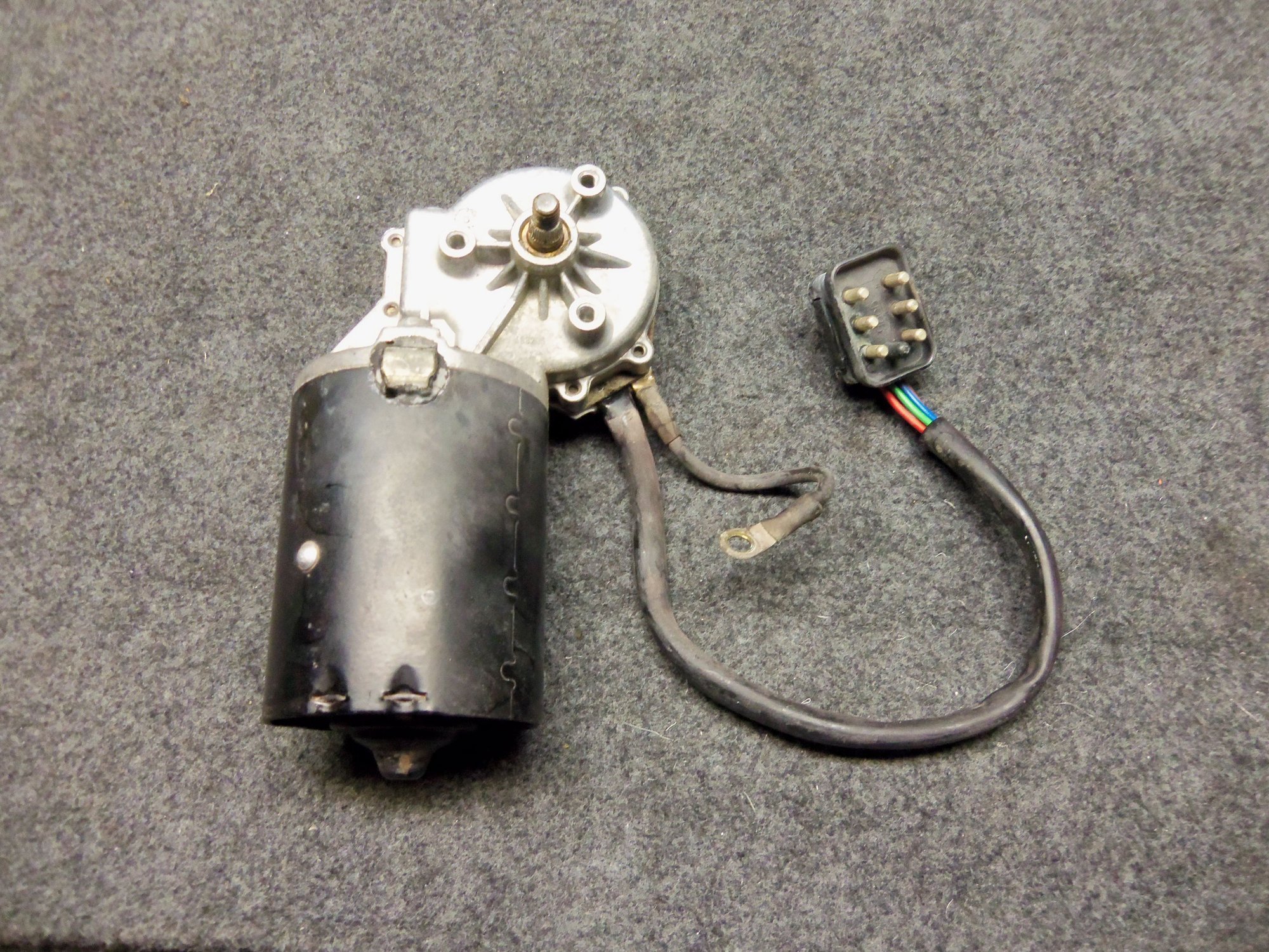
Looks relatively clean on the outside.
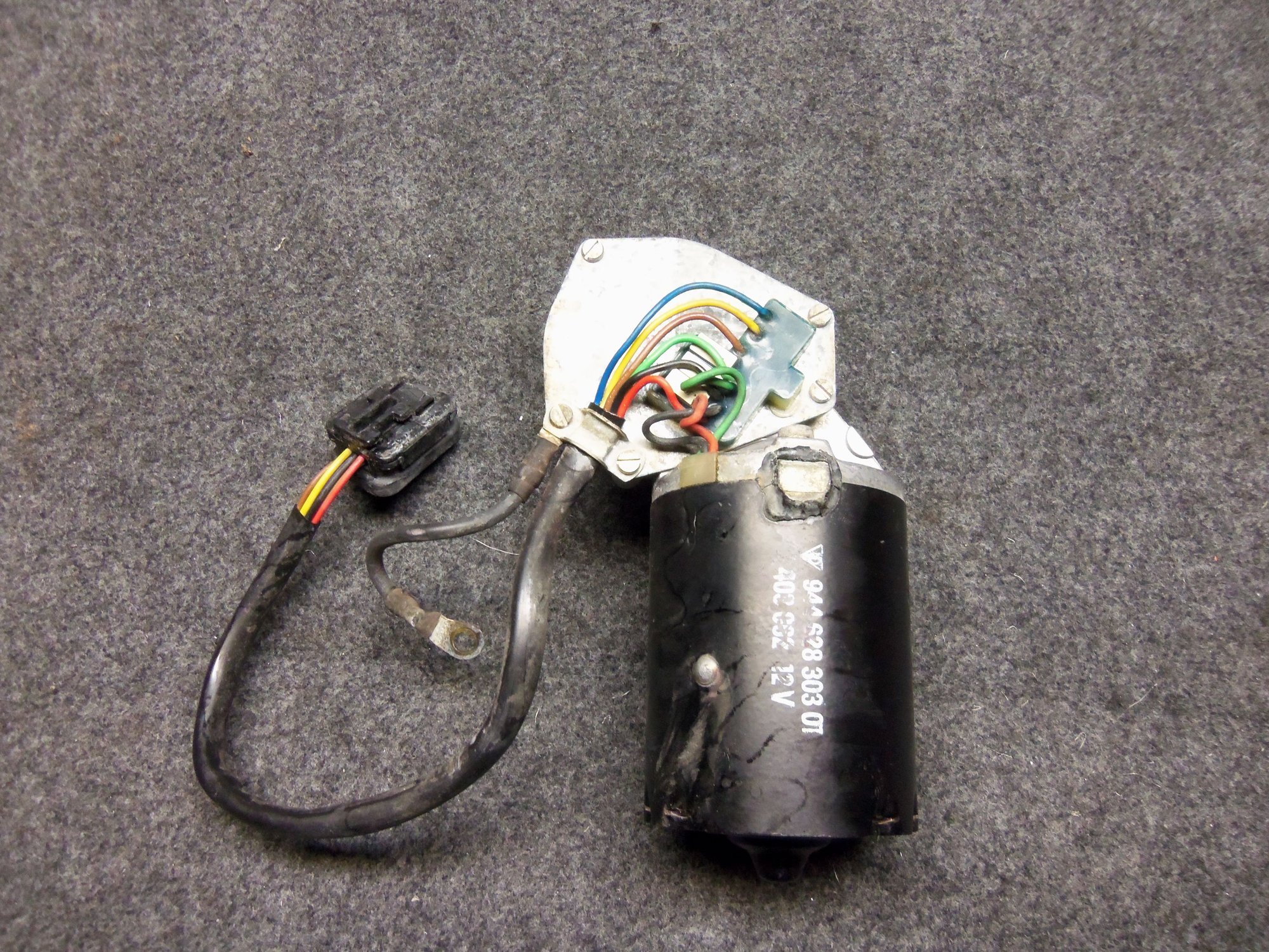
No damage to the wiring on the gear casing cover.
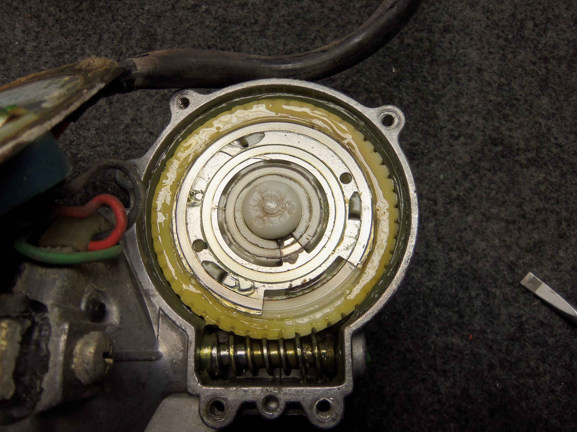
Grease looked surprisingly good.
No damage or corrosion on the gear or shaft.
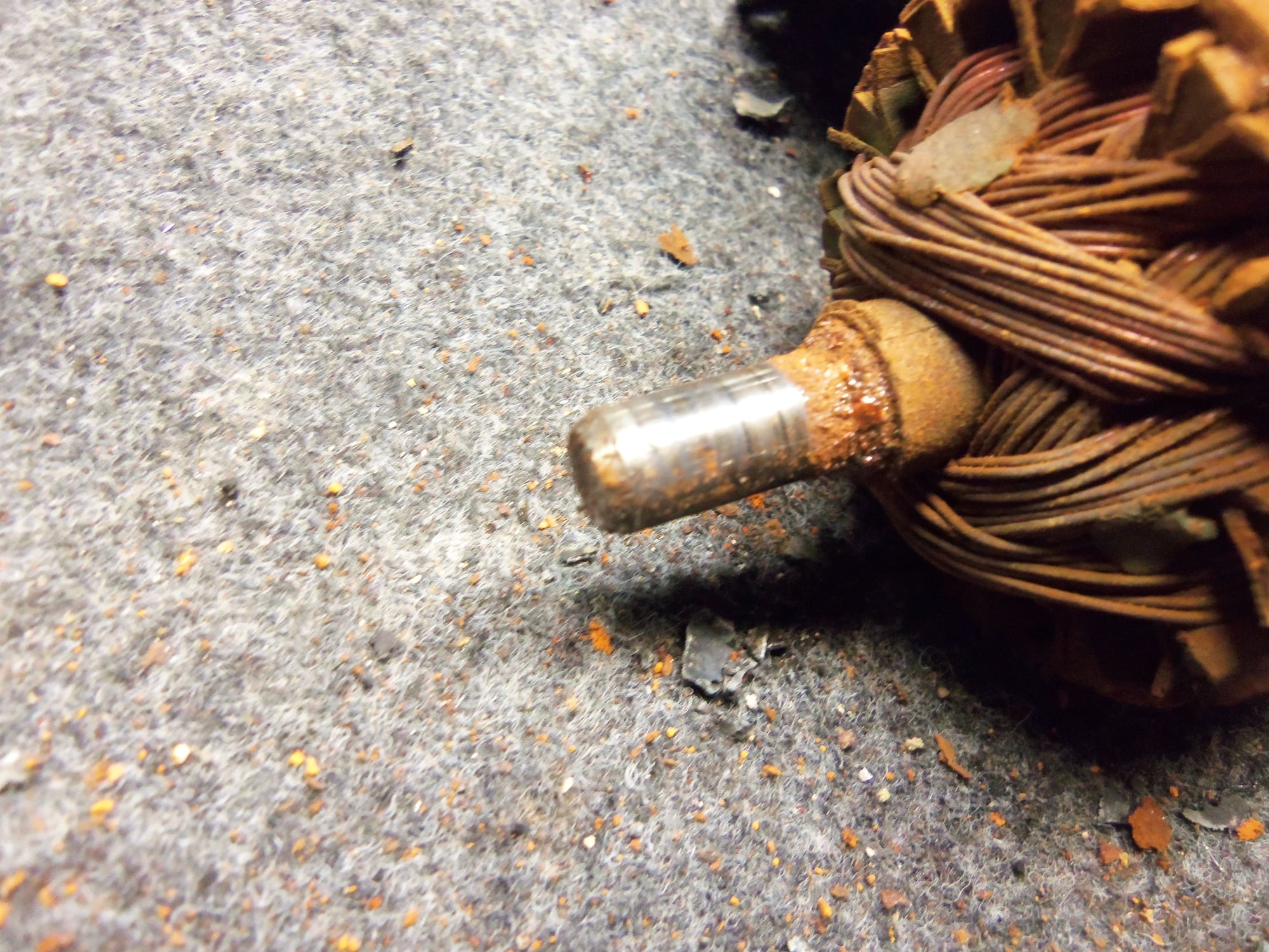
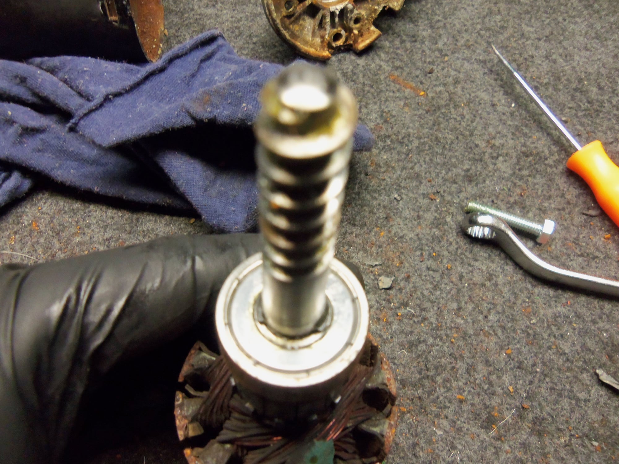
No real corrosion on the armature shaft where it seats in the motor casing end bushing.
Ground screw and grounding braid. Eeeew...
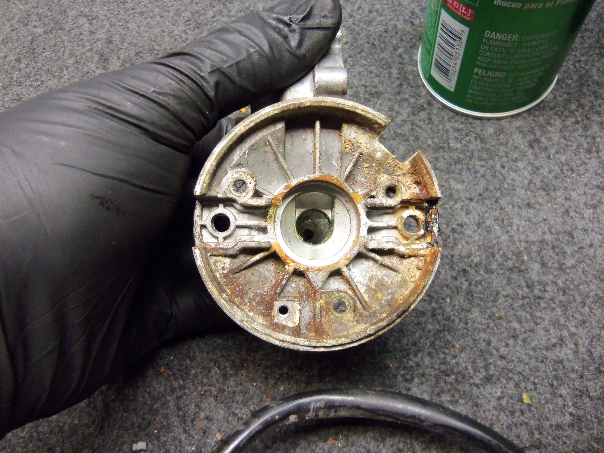
Broken rock hard brush plate insulator locating nubs in the gear case.
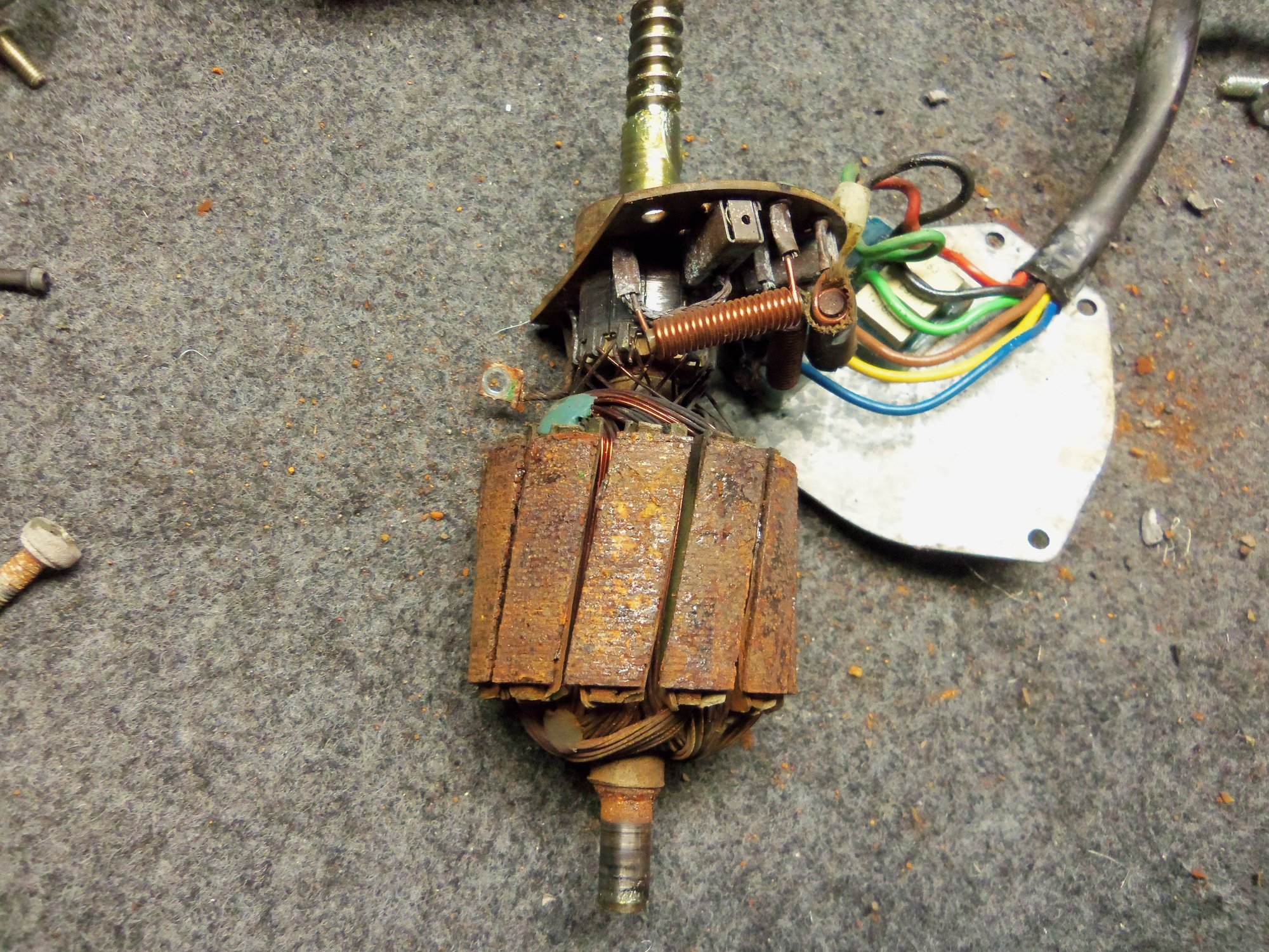
Armature laminations were pretty hateful looking with rust.
Commutator had seen better days, but was not scarred or burnt.
Little circlip on top of the bearing inner race.
Gear case jigged up in a vise in an attempt to adhere the brush plate in place.
Improved commutator.
Once I knew the motor ran, I potted the seam between the gear casing and the motor casing with Permatex non-hardening sealant. I may have used a little too much, as it took two days to dry.
Heavy coating of Permatex non-hardening sealant to pot the motor/gear casing seam.
Reassembly of the wiper transmission and installation of the motor was straightforward and relatively anticlimactic. I had taken lots of photos, and used the diagrams from PET and the WSM to know which washer and clip went where. I did mark the motor gear output shaft in relation to the crank lever arm. That was good, because it is splined, and can go on anyway. I think I am safe putting it back where it was, as the wipers parked in what looked like a good spot at the base of the windshield. I will tweak the positioning if necessary.
Match mark for gear output shaft and crank lever arm.
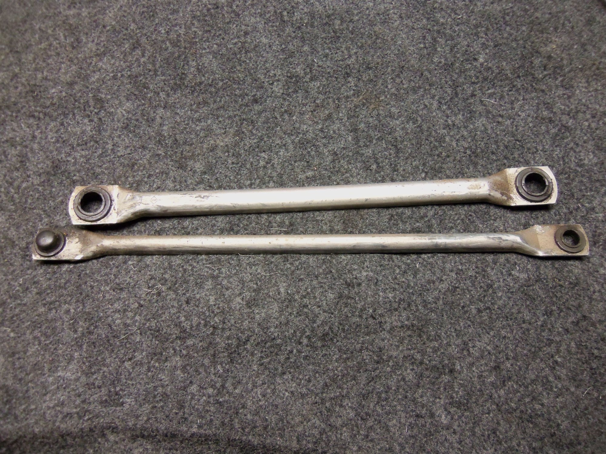
I reassembled the wiper pivots and arms with CV axle grease to lubricate the bushings and such. I did make a deviation from what I found. The plastic pivot bushing on the end of the passenger's side transmission arm was a closed top bushing. The bushing on the drive motor end of the passenger's side transmission arm was an open top bushing. This bushing was on top of the pivot ball on the crank arm. When I reassembled it, I swapped the passenger's side transmission arm end for end, putting the closed top bushing on the pivot ball on the end of the drive crank arm.
Closed top bushing at the pivot end of the passenger's side transmission arm.
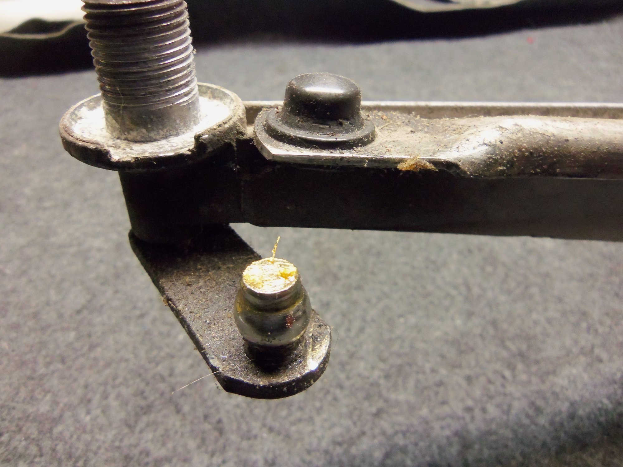
Open top bushing at the drive crank arm end of the passenger's side transmission arm. It is the one at the right, on top of the crank lever arm.
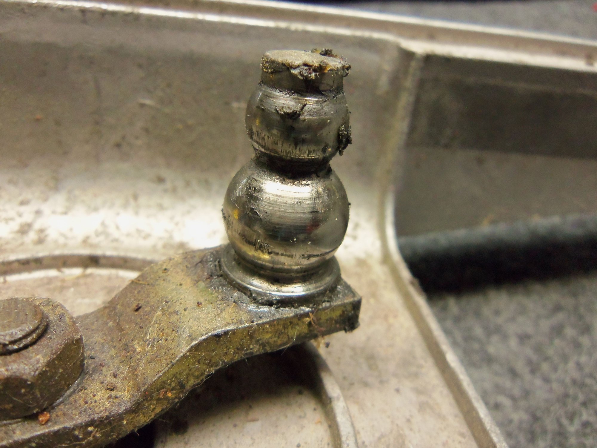
Large and small pivot ***** on the drive crank arm lever.
Comparing the transmission arms.
Reassembled with the closed top bushing on the drive crank arm end of the passenger's side transmission arm.
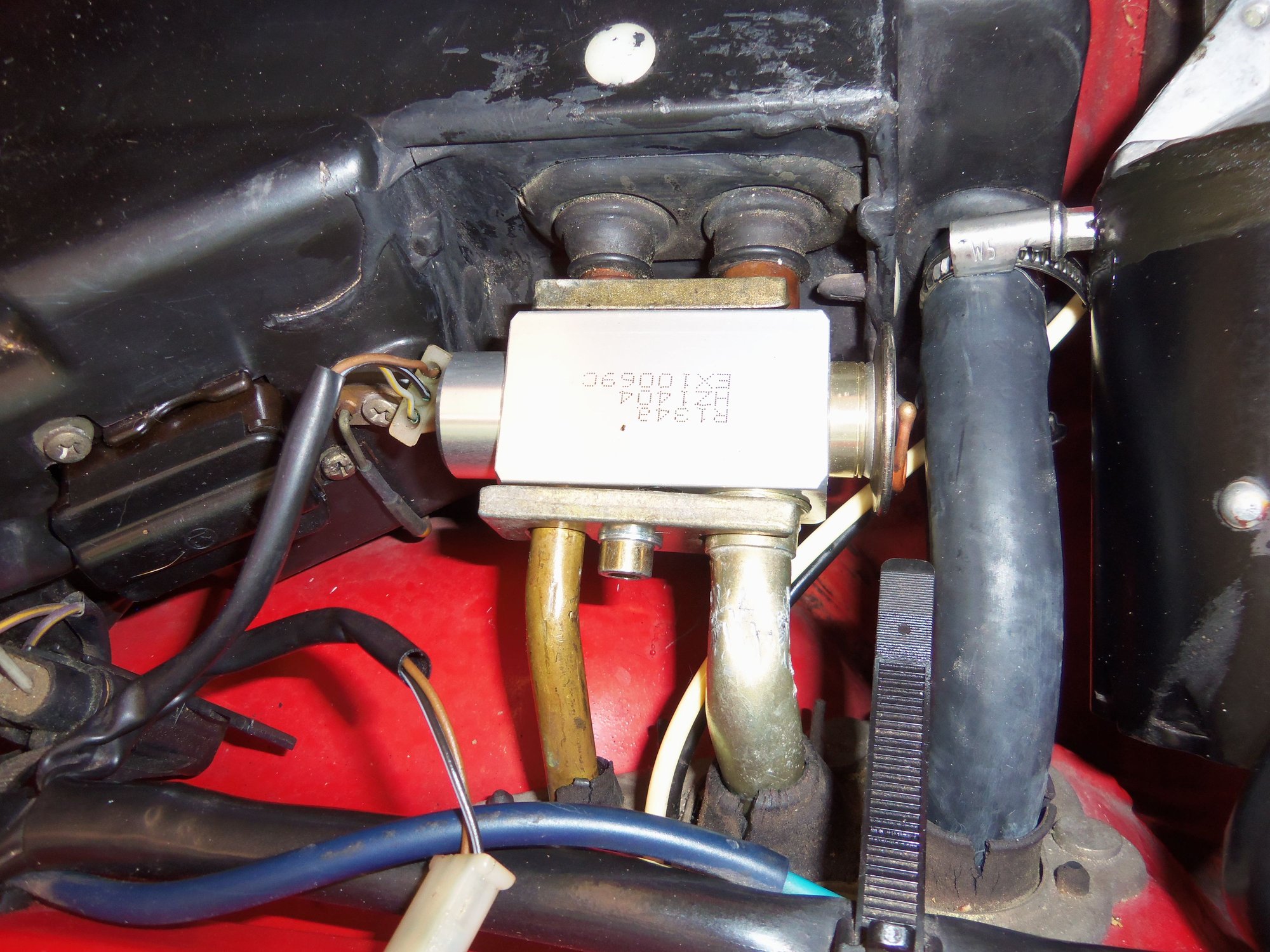
As for the AC plumbing under the cowl and along the passenger's side inner fender, I took some additional photos:
Better picture of the new expansion valve and the AC lines going to it. I am going to remove the keeper plate, verify it is flat, and double check that the large line on the right is properly seated in the expansion valve. If I remember correctly, that is how it looked when assembled to the old expansion valve.<br/><br/>For what it is worth, I did not leave the vise grip scars on the large metal AC line on the right. That was there before me...
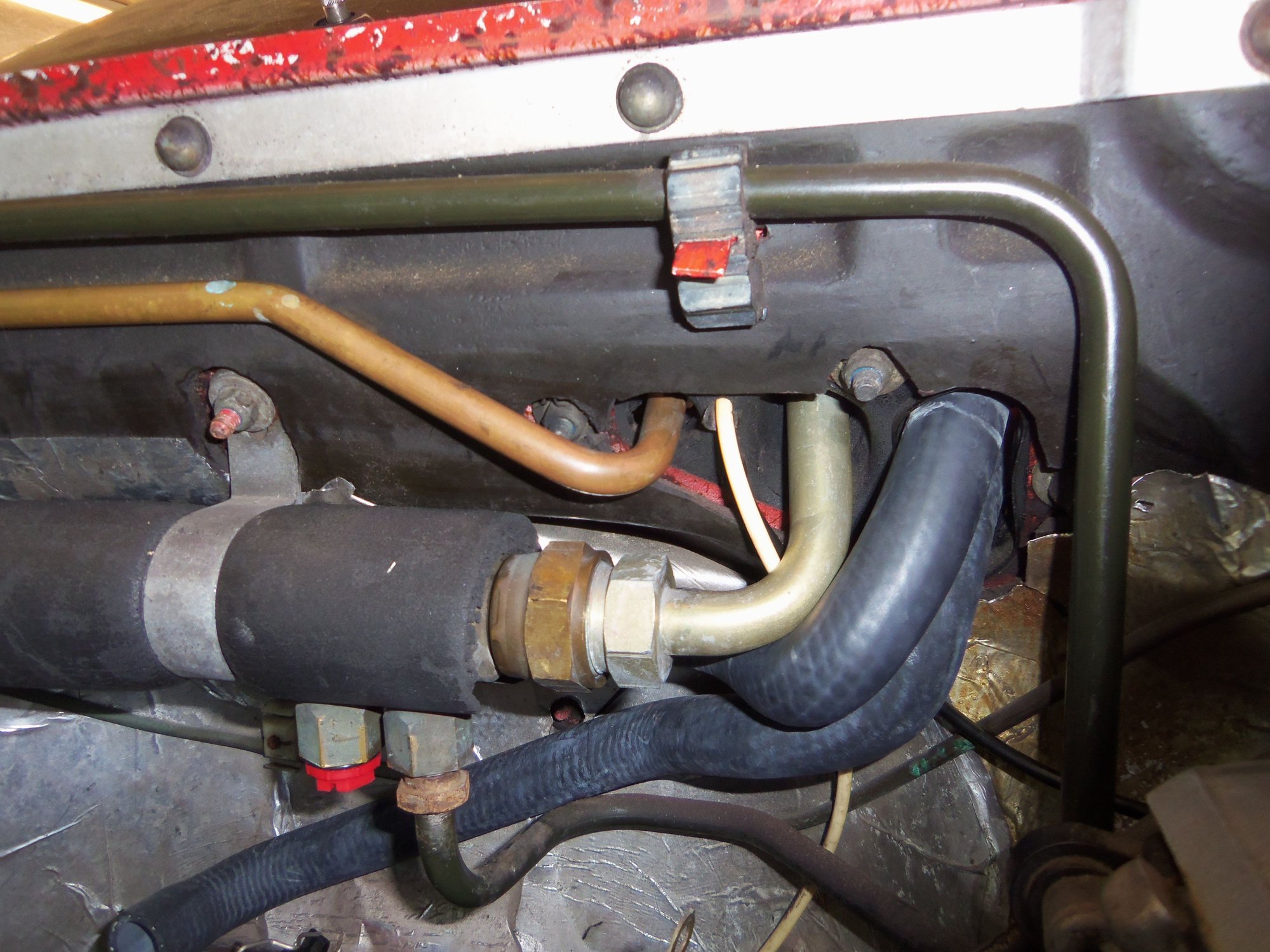
Shot of AC lines and heater hoses routed down and out through the cowl fire wall.
Shot of AC lines and heater hose running along the passenger's side of the cowl firewall.
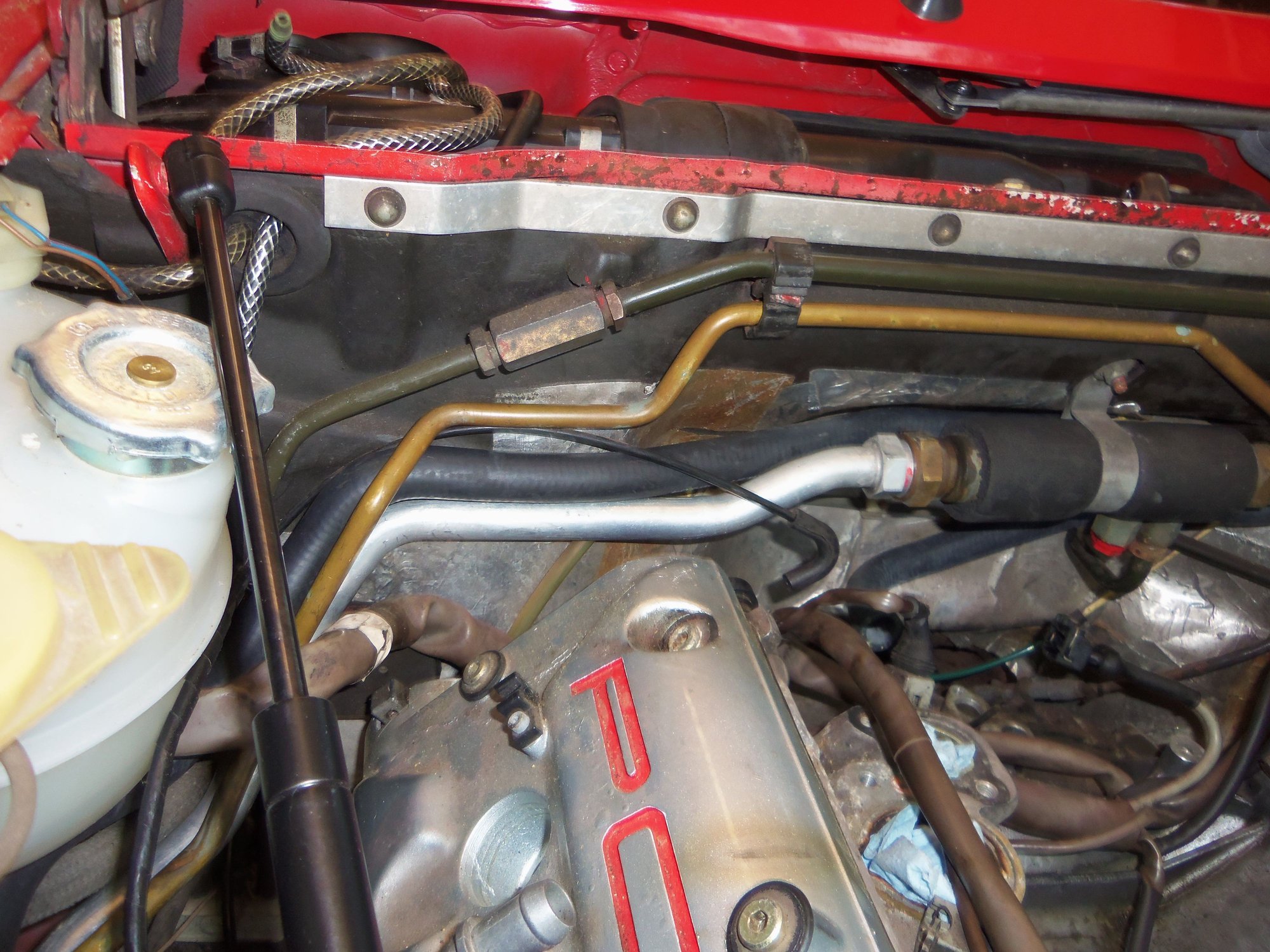
Shot of AC lines, heater hose, and powdercoated metal water tube near the coolant overflow reservoir.
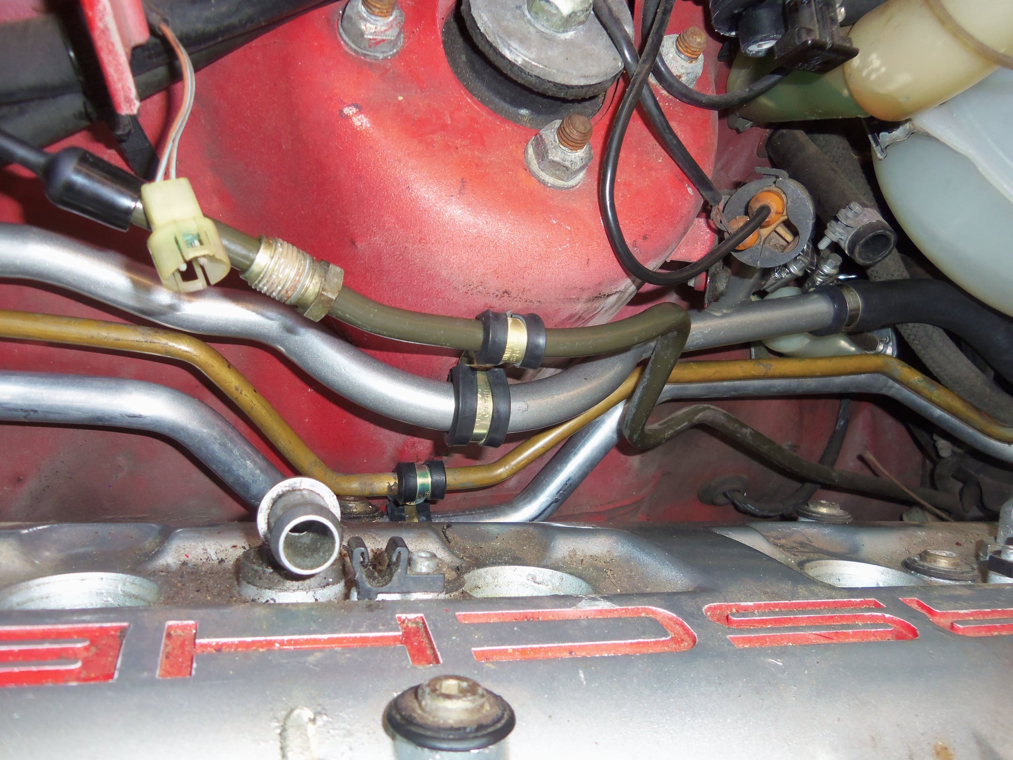
Shot of the fuel supply line, metal water tube, AC lines, and the new P-clamps holding them in place.
Shot of the ends of the metal water tube and AC lines. All are capped off for now.
Thanks for your contribution, Seth. Send me your address by PM.
Thanks, Jerry! PM replied to.
Originally Posted by Rob Edwards
This is a very good idea, you do _not_ want to install wiper arms until you are 110% sure the short lever on the motor shaft is clocked correctly and the arms are rotating as they're supposed to. We did not do that, and it wasn't pretty. Ask William how I know.
Start with strips of tape on top of the shafts as indicators, and watch them turn.
Will do, Rob!
Thinking my way through this, how will I know to adjust the crank lever arm? The transmission arms won't 'park' in the right place?
Or is it the actual back and forth rotation won't be correct at each wiper pivot?
I remember looking in the WSM, all it overs is aligning the wiper arms themselves to the edge of the windshield.
The first picture in your 1st post shows the lever arm pointing to about 2 o'clock, maybe 2:30. And you mentioned that you did make a refence mark, I missed that pic on my 1st read-through. So you should be fine, as long as the motor behaves the same way post-reassembly. But still worth verifying the park, intermittent, low, and high-speed operation without arms installed.
For dummies like me that _didn't_ clock the lever arm, it's just a matter of running the motor with the wiper arms not installed, you want them to be turning in synchrony and sweeping whatever angle they sweep. Dr. Bob will be along with an algorithm that defines the effect of rotating the lever arm for each 'knurl' that it might off.
The 16th photo in post #21 shows the match marks that I made on the crank lever arm and the gear output shaft.
What you have said makes sense. Even with the match marks, I will still observe the operation of the wiper transmission and pivot posts for several cycles.
Then put the wiper arms on.
Thanks for your advice, I very much appreciate it!
Excellent work Seth
One thing I noticed it that your cowl cover seems to be missing the cowl panel gasket, (928 559 251 02) that goes between the cowl panel and windscreen.
Also, the VW relay for intermittent wipers is a good alternative if the delay resistor wheel is cactus.
"One thing I noticed it that your cowl cover seems to be missing the cowl panel gasket, (928 559 251 02) that goes between the cowl panel and windscreen."
Hi GP - do you have a photo of that part? It is not shown on the diagram but listed as a part. Did not have that on my old cowl cover or the new I bought.
Thanks for the write up Seth. Great reference when we are working in that area.
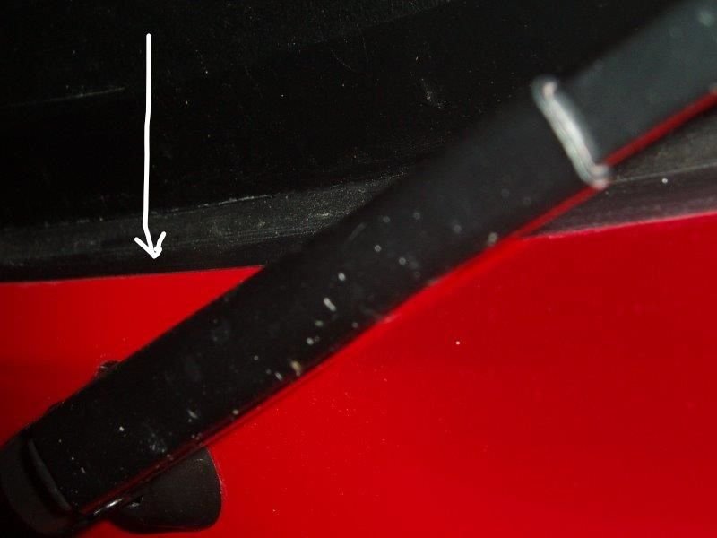
This is what I assume is the 'cowl panel gasket' listed in pet. It runs the full length of the cowl panel. It fits onto the cowl panel and after the panel is installed the 'gasket' presses against the windscreen.
Sorry, but she needs a wash.
Last edited by G.P.; 06-15-2017 at 08:43 AM.
Reason: Changed photo


 06-14-2017, 02:45 PM