When you click on links to various merchants on this site and make a purchase, this can result in this site earning a commission. Affiliate programs and affiliations include, but are not limited to, the eBay Partner Network.
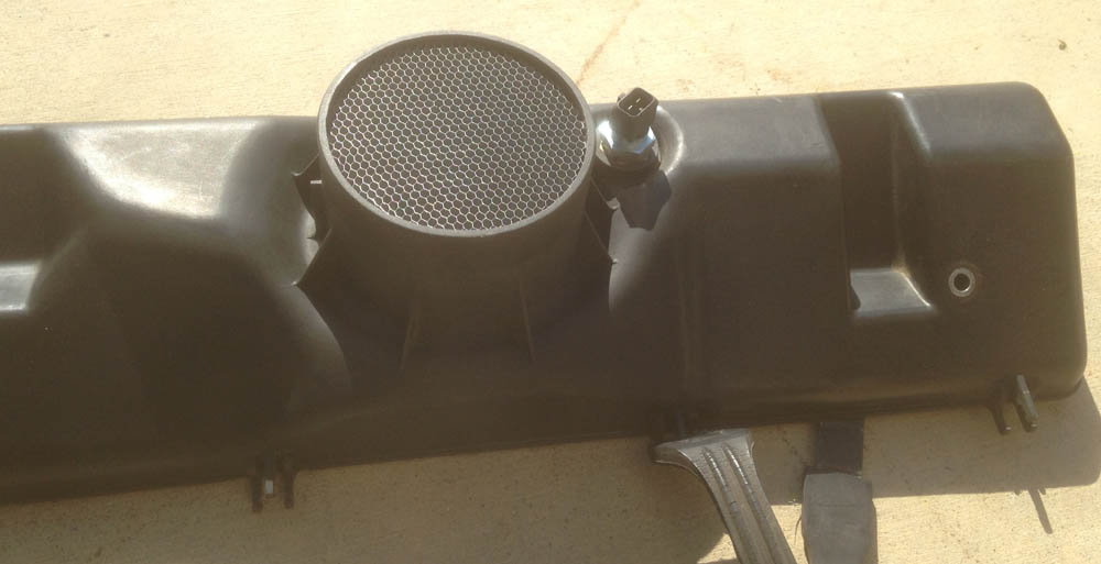
I just finished installing PorKen chipset version 4 and an '87 FPR. While in there I added a 1" thick honeycomb inside the air cleaner box exit port. A friend 928noobie (Matt) who is no newbie in reality, gave me the tip to reducing air turbulence of the air entering the MAF and airflow system. Anyway I figured it could do just that and the cost was under $20 why not try it.
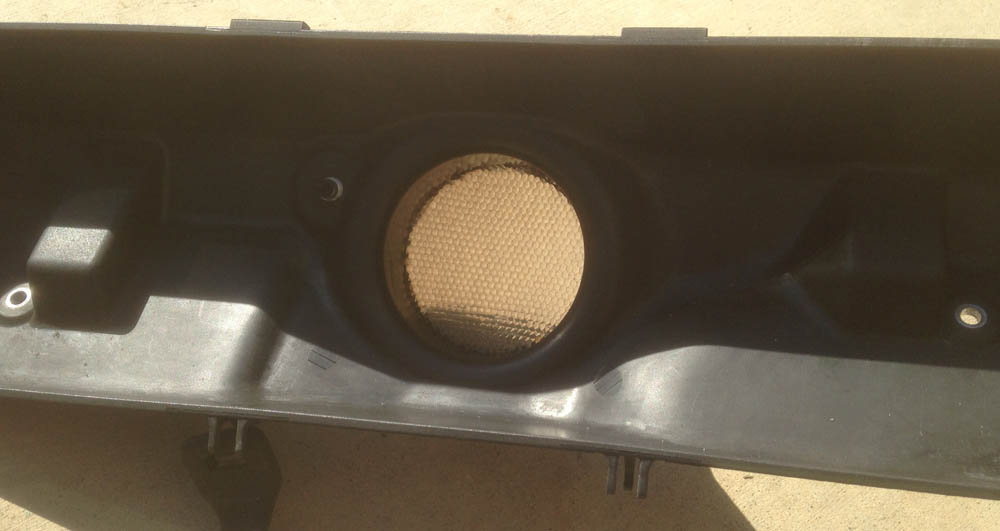
Here are a couple pics of it in place in the plastic housing.
I made two changes at once so I say the honeycomb made any change but the car is running very nice with noticeably more power and no obvious flat spots in acceleration.
Just thought I would share. If you have been installing new elements such as an MAF, O2 sensor, Temp sensors, etc. the PorKen chipset upgrade is an easy change to make and certainly worth the investment.
A bit on changing my MAF. While I could get a blinker test done before I bought the rebuilt MAF from Roger, It required a setting of about 750 ohms resistance. After the change it tuned at about 400 ohms very close to the normal 380 defined for static MAF CO tuning.
I am of the school of if it ain't broke don't fix it but in this case all those who recommended it were right. The $350 for it was worth the change.
Anyone have any suggestions on fine tuning after the chipset change?
This is on my '86.5 USA 5.0 32 valve.
We've been using those for several years now with supercharger installations where there is a 90 degree elbow just before the MAF, there are a few threads on it. With a 90 just before the MAF, air is not entering the meter uniformally and the straightener proved to even things out for consistent tuning.
With installations where an intercooler is sitting directly over the MAF, such a straightener proved to be no benefit. With the stock air filter sitting evenly over the MAF, the design of the lower airbox does the same, and along with the stock screen on the MAF Porsche did a great job designing things for good even air flow.
These air straighteners do not improve airflow, they even out the air flow so a more consistent amount hits the measuring wire. Many OEM applications from Jaguar, to Saab and GMC have something similar before the MAF.
Good feedback. Will do a search of topics. Got mine at http://www.saxonpc.com
I would not say it adds power but may take some bumps out of the acceleration. The air filter box is pretty good but it cant be delivering as smooth of supply over the diameter of the MAF for the simple reason of the converging air from the middle to its edges. Wish we had some dyno data.
What about tuning for the V4 chipset and the blinker test. Any comments?
Steve
On naturally aspirated models the honeycomb can and does stabilise idle a bit but it also adds a flow restriction that will cost a small increment of power. That you installed this with Ken's chipset in all probability masks the small [negative] increment but as long as you are happy with the total overall effect that is all that really matters.
I tried this on my S4 motor with Roger's EIS system that has an improved inlet flow path. The idle was a bit more stable but I felt the system was a tad strangulated so dumped the honeycomb.
As to what causes these issues there has been a lot of debate. I personally believe reversion pulses have quite a bit to do with it and the stock inlet system is compromised by a lack of volume for the lower plenum [no headroom].
In earlier years when I tried the K&N filter in the stock filter carrier, I noticed that the filter had a pronounced "ring of darkness" [due to captured crud] the same size as the MAF aperture- this told me that air flow was anything but even across the air filter matrix and two air streams going "head to head" as they fight each other to get into the motor does nothing for the plot.
I also believe turbulence has nothing to do with the issue. Folks throw this word around not really understanding what turbulence really is- it is a flow phenomena defined by the Reynolds number for that particular flow stream. Folks confuse this with localised flow disturbances caused by "path of least resistance". Reversion pulses exist- this is why the GT has a higher idle speed than the S4. Reversion pulses are not good for MAF stability which is why John Speake adopted a MAP sensor system to his ST2 kit enabling the use of lumpier cams that typically need a higher idle speed for stability- not too much of a problem on manual transmission models but not suitable for automatics.
Your model has no knock sensors so the timing is more conservative- as I understand Ken's chips take advantage of this margin leaving less on the table as it were. Your cams have a wider LSA [Lobe separation angle] compared to the GT so has less issues wth the reversion pulses [or so I understand].
Trust the above is an accurate assessment of what is going on. At the end of the day the inlet and the exhaust form an integrated system and there are no "free lunches". Porsche did their best to apply safety to an advanced [for its time] concept. When the S4 was introduced with knock control Porsche reduced those margins relying on the system to reign in any cylinders that are misbehaving. When it is working as designed the S4 and later can pull up to 9 degrees of timing dynamically on individual cylinders and if the system is not healthy [failed knock sensor or Hall trigger] it pulls 6 degrees of timing across the board- 3 degrees "pulled timing" makes a noticeable difference one can feel.
My experience with the comb is that it evens the pressure against the MAF wire and helps to smooth peaks and troughs. It serves as a signal stabilization aid and I was very pleased with the improvement in smoothness and stability...helped give more of that "connected" feel.
not sure how it would negatively impact power...I would think since it's improving signal consistency if anything the engine might be able to generate more power consistently since the ECU is now responding to some cleaner inputs?
not sure how it would negatively impact power...I would think since it's improving signal consistency if anything the engine might be able to generate more power consistenly since the ECU is now responding to some cleaner inputs?
There is little to no benefit from these screens at WOT, at least under the tested we did with supercharged cars. So when talking about power, such an addition to the intake tract is only causing a restriction.
Albeit a very slight one, any restriction can only negatively effect power output, not help it. We never noticed a drop in power testing them on the SC cars though.
We also did some testing on a couple of Corvette race cars. Comparing the data logs on the dyno, you couldn't tell the difference between the two, made no difference in the areas of the map these are tuned for. Since idle and cruise are of no concern with these engines, the straighteners were never used.
If the screen increases driveability everywhere else in the rev range, then the positives may outweigh the negatives. Especially as Fred said above, with the revised chips.
Thanks Fred for that explanation. I know something about air flow and pipe restriction from designing model air plane racers and water flow systems. Certainly there is a restriction in play with the honeycomb. Only a tiny lost of square inches of opening but the wall friction of all the small holes is the more dynamic restrictive effect. What I don't know is how much the remaining air system and exhaust side nulls any effect on the engines ability to breath. When I think about the airflow through the throttle body this small difference in the delivery of air is probably irrelevant to the engines ability to breath but most relative to changes in the way the MAF adjusts the mixture.
One effect I think I experienced when blinker testing was the CO adjustment was not as sensitive at idle. Fred's comments about the honeycomb's stabilizing effect on idle seems consistent with my experience. I plan to test again then pull the honeycomb and see if the CO blinker test is effected and again becomes sensitive. Currently the blinker flashes as it should, slowly with the ICV active and rapidly with it jumped. I have not done the static ohms test but will before I start the car again.
Will drive the same bit of road with WOT with and without the Honeycomb looking for changes. I will set the CO adjuster to about 380 Ohms and ignore the blinker for this test. I have to wait for the streets to dry as it is raining today.
In the end among my highest concerns is to not put my car out of a passable condition for smog testing. Owning this car in CA can be a limiting factor.
Cheers, Steve
Very nice work Jeremy, Seeing your video was great. Getting the various inputs and experiences in this area has been interesting to say the least. I guess the expected result is no gain in power but perhaps in smoothness of operation in normal driving. So far the $16 the honeycomb cost has been worth every penny in entertainment value alone.
When you study the results derived in ST2 I see the MAF output signal fluctuating randomly in the range of something like 120 to 140 MAF flow units. This has nothing to do with turbulence and has everything to do with flow disturbance most likely caused by reversion pulses. Whether or not these variations in signal out put are causing the ISV to react I am not sure as I was never looking for that. The honeycomb seems to help even out the flow disturbances - when I tested this the MAF signal had a narrower [i.e. more stable] signal range so I concluded it does do something positive.
When you study the results derived in ST2 I see the MAF output signal fluctuating randomly in the range of something like 120 to 140 MAF flow units. This has nothing to do with turbulence and has everything to do with flow disturbance most likely caused by reversion pulses. Whether or not these variations in signal out put are causing the ISV to react I am not sure as I was never looking for that. The honeycomb seems to help even out the flow disturbances - when I tested this the MAF signal had a narrower [i.e. more stable] signal range so I concluded it does do something positive.
Above jibes with my experience in driving as well..it feels a little smoother...what's interesting is I didn't notice there were very small surges happening until they disappeared...to me it helps give a more "connected" or "direct" feeling between the foot and the power..when I replaced the MAF recently I took the old screen (with the comb attached to it) and transferred it to the new MAF.
There is little to no benefit from these screens at WOT, at least under the tested we did with supercharged cars. So when talking about power, such an addition to the intake tract is only causing a restriction.
Albeit a very slight one, any restriction can only negatively effect power output, not help it. We never noticed a drop in power testing them on the SC cars though.
We also did some testing on a couple of Corvette race cars. Comparing the data logs on the dyno, you couldn't tell the difference between the two, made no difference in the areas of the map these are tuned for. Since idle and cruise are of no concern with these engines, the straighteners were never used.
If the screen increases driveability everywhere else in the rev range, then the positives may outweigh the negatives. Especially as Fred said above, with the revised chips.
Based on simulations, logic, and observations, I believe the stock S4 intake manifold only sees mass flow in the correct direction, even at idle. Bigger is not always better in the plenum department. The zip tube being at 90 degrees to the throttle and MAF (the Porsche way) should help. Furthermore, what matters for tuning is consistency less than "correct" measurement.
MAF and/or LH give erroroneous readings, but I believe those are not related to mass flow reversion at the MAF. Porken's chips smooth out the MAF sensor reading anyway, so those should not be a concern once the chip is installed. As mentioned above, the flow is highly likely to be turbulent (instead of laminar) at the sensor, but how it's distributed and how straight it is is not known. Tight wire mesh such as the stock screen has a surprisingly high restriction, but will in theory make the sensor reading more consistent. My understanding is that very thin wall coarse honeycomb has less restriction than a wire mesh, but it still straightens and evenly distributes the flow.
Big cams have issues with plenum manifolds, but in my opinion it's not so much MAF/MAP/TPS load measurement (when implemented and smoothed correctly) but other issues related to cylinder filling during overlap. Again, I believe that with appropriate smoothing one can get all load measurement methods to work. What can't be smoothed over is the instability of the actual cylinder filling with high overlap cams and a plenum manifold, especially if the plenum is large.
Getting clean, straight even airflow across the MAF does wonders for it.
Don't know the geometries of the 928 setup so can't postulate, but can share MAF experience from my 944...
I had a MAF conversion for a while and played with MAF sensor "clocking" to get it to run smoothly - the 944 has a ~45 reverse bend from the air box to the throttle body and putting the MAF on the short side radius made it screwy...switching to the long side radius (with the MAF in roughly the center of the pipe this was only a minor shift in its actual location) it smoothed out greatly...I then later added a giant aluminum "bell mouth" at the MAF inlet around which the filter clamped and it was like buttah..

 03-21-2017, 08:18 PM