
Effect of ride height on alignment and other queries
 12-10-2015, 03:04 AM
#16
Rennlist Member
Thread Starter
steering needs to be centered, best if rack is also centered, good if steering wheel is centered when rack is centered. The steering geometry includes "Akerman Effect", letting the inside wheel turn more than the outside wheel when going around a corner. Moving the steering from centered will offer toe-out relative to wheels straight ahead.
MK and I go back and forth on the available accuracy of his stick-against-the-tire method. I argue that the tire sidewall is hardly a solid place on which to base a measurement.
.
At the moment my current concern is to protect the front tires and a reasonable total toe-in setting will achieve that. My test drive yesterday proved something was out and later visual inspection confirmed this using my "single eyeball" method. I reduced the left toe-in adjustment and visually it appeared to be the same as the right hand side.
Then last night I did my laser check for total toe and the readings are taken from the rim- not the tire so the toe spread I reported is from a diameter of approx 18 inches as opposed to Mark's calcs based on 20 inch so I reckon I am close to a temporarily acceptable reading. At the moment i have both beams running down the side of the car parallel to each other but not accurately to the car thus I cannot measure toe on each side. Last night I took readings from the hub centre cap faces to the beams so I now know the difference between front and rear and can set up the beams so that both sides are parallel to the car and not just each other. This way I can then measure toe on both sides.
I am confident my rack is centred correctly relative to the steering wheel - I just need to get the car on to the Hunter rig I normally use. Before doing that I want to replace the dog bone bushes [or replace with my spare units] and I also want to repair the rear cam adjustment mechanism using Carl's inserts once they arrive. Just that I do not want to go to the Hunter machine twice- rather do it all in one visit hence the need for an acceptable temporary solution.
When I take the car to the Hunter machine I supervise the alignment personally and on the last visit they actually let me do the adjustments myself- never had a problem. Like you say it is all to easy to scrub a set of tyres and not even know anything was going wrong until it was "too late".
Rgds
Fred
 12-10-2015, 03:30 PM
#17
Rennlist Member
makes sens, as long as there is no other errors introduced with the set up. just for giggles...make a mark at the front and rear of the tire using one of those straight edges and see what the difference is (front to rear, both tires).... see if we can get the same value. i think you will.
no lasers needed... just a magic marker and a straightedge.
no lasers needed... just a magic marker and a straightedge.
Mark,
Dr Bob's laser levels are identical to mine- the black projector or whatever it is called that the beam emits from is polarised [correct term?] in that rotating it through 90 degees creates a beam that can be oriented either vertical or horizontal [or any angle in between]. I orient mine vertical so that when projected onto the wall I see a clear vertical line.
In my situation at the moment I project two parallel beams down the side of the car sitting each laser level on top of two axle stands thus I have a vertical beam passing along the side of the car close to the wheels and then I simply measure the distance from the beam to the front wheel rims forward [9 0'cloxk]and aft [3 O'clock] at the horizontal centreline. During the setup process I ensure that the separation of the two beams is the same in front of and behind the car. You can do this referencing the laser line image on the floor or you can do it projected onto a wall. The longer the laser line length the more accurate the setup will be.
The difference between the readings for both front wheels gives the total toe. To understand the toe setting for each wheel I will need to calibrate the beams to ensure they are parallel both sides. I now know the difference between the position of the front hub caps and rear hub caps so that should be relatively easy to set up- a bit fiddly but "doable".
Rgds
Fred
 12-10-2015, 10:28 PM
#18
Chronic Tool Dropper
Lifetime Rennlist
Member
Lifetime Rennlist
Member

Fred--
Find the middle of the car front and rear, put a piece of paper tape on there with a vertical line. Then measure N inches either side of the lines front and rear, put your lasers (or thread or string) there at 12-ish inches off the floor (center of tire height). Use a pocket scale to measure from laser/thread/string to rim edge. Super easy, and easily repeatable setup as your height gets to target and your toe is kept perfect.
My original gaol with the lasers was to get the measurements into a range where normal folks could get repeatable accurate settings without having to remember their high-school trigonometry. Getting readings from the edge of a 17" or even 20" rim means tiny graduations and interesting math. Letting the laser stretch the bar out to 43" from center means bigger graduations on the tape measure (3/8 - 1/2" delta) that mere mortals can easily duplicate.
12-11-2015, 04:13 AM
#19
Rennlist Member
Thread Starter
Fred--
Find the middle of the car front and rear, put a piece of paper tape on there with a vertical line. Then measure N inches either side of the lines front and rear, put your lasers (or thread or string) there at 12-ish inches off the floor (center of tire height). Use a pocket scale to measure from laser/thread/string to rim edge. Super easy, and easily repeatable setup as your height gets to target and your toe is kept perfect.
My original gaol with the lasers was to get the measurements into a range where normal folks could get repeatable accurate settings without having to remember their high-school trigonometry. Getting readings from the edge of a 17" or even 20" rim means tiny graduations and interesting math. Letting the laser stretch the bar out to 43" from center means bigger graduations on the tape measure (3/8 - 1/2" delta) that mere mortals can easily duplicate.
Find the middle of the car front and rear, put a piece of paper tape on there with a vertical line. Then measure N inches either side of the lines front and rear, put your lasers (or thread or string) there at 12-ish inches off the floor (center of tire height). Use a pocket scale to measure from laser/thread/string to rim edge. Super easy, and easily repeatable setup as your height gets to target and your toe is kept perfect.
My original gaol with the lasers was to get the measurements into a range where normal folks could get repeatable accurate settings without having to remember their high-school trigonometry. Getting readings from the edge of a 17" or even 20" rim means tiny graduations and interesting math. Letting the laser stretch the bar out to 43" from center means bigger graduations on the tape measure (3/8 - 1/2" delta) that mere mortals can easily duplicate.
Great minds think alike! The trick bit is trying to find the vehicle centre line. I use the face of my hub caps as my reference point knowing that there is a 3mm width difference between front and rear axles [I run a 24mm spacer on the rears]. At the moment I sit the lasers on two axle stands and juggle the position of the laser beam until it is the correct distance relative to the front and rear reference points. What I really need is a mount for the lasers where I can both swivel and travel. Once the beam is aligned to my satisfaction I simply measure the distance from the beam to the rim edge on the horizontal centreline of the wheel. I reckon I can measure this difference to within 1mm given I am looking for 2mm to 3mm each side [0.25 to 0.376 degrees] and that is enough to get a toe-in measure that will not trash the rubber and leave a margin of safety for the likely further suspension settlement.
Regards
Fred
12-11-2015, 12:10 PM
#20
Rennlist Member
Here is the setup that I use to set toe, based on efforts by Earl Gilstrom, Andrew Olson, Dr. Bob and others. It's basically the same as Dr. Bob's setup except the target for the front wheel is attached to the rear wheel, and vice-versa. This ensures that each wheel is correctly aligned relative to the car's centerline, i.e. no "crabbing".
In the pics below I am checking the right-front wheel of our GTS, shooting the target at the rear wheel.
Here's the laser on the front wheel. I used plywood for the bracket, the steel bar stock is for the laser to stick to. Bungee hooks are covered with shrink-tubing, I need a better arrangement for that.
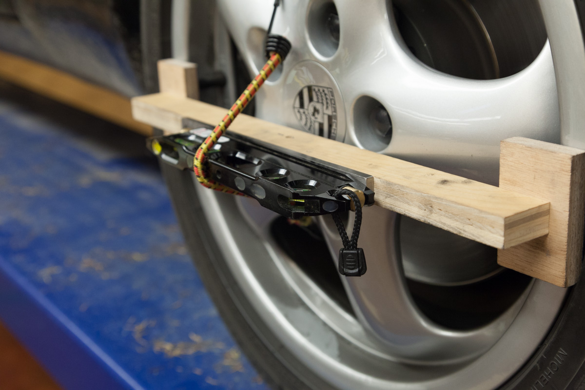
Here's the target on the rear wheel. The center line is where the target scale would go with zero offset front/rear, this is our GTS so the offset is large-- rear track is wider. For the S4 and GT it is only a few mm. The target offset would be reversed when shooting from rear wheel towards the front-- the backside looks the same except the offset is outwards, not inwards.
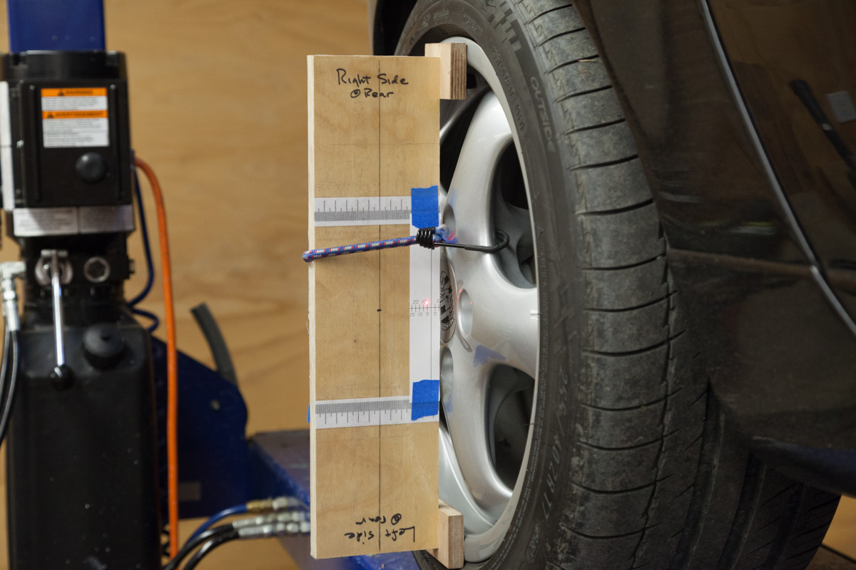
The "zero" line on the target is established by sitting both laser and target assemblies on any flat surface. Then measure the difference in "track" front and rear, i.e. difference in width between the outer rims, front and rear. I do this by dropping a plumb bob from the laser bracket at each wheel, marking the position on tape and then moving the car and measuring the tape marks. Half the difference is the target offset.
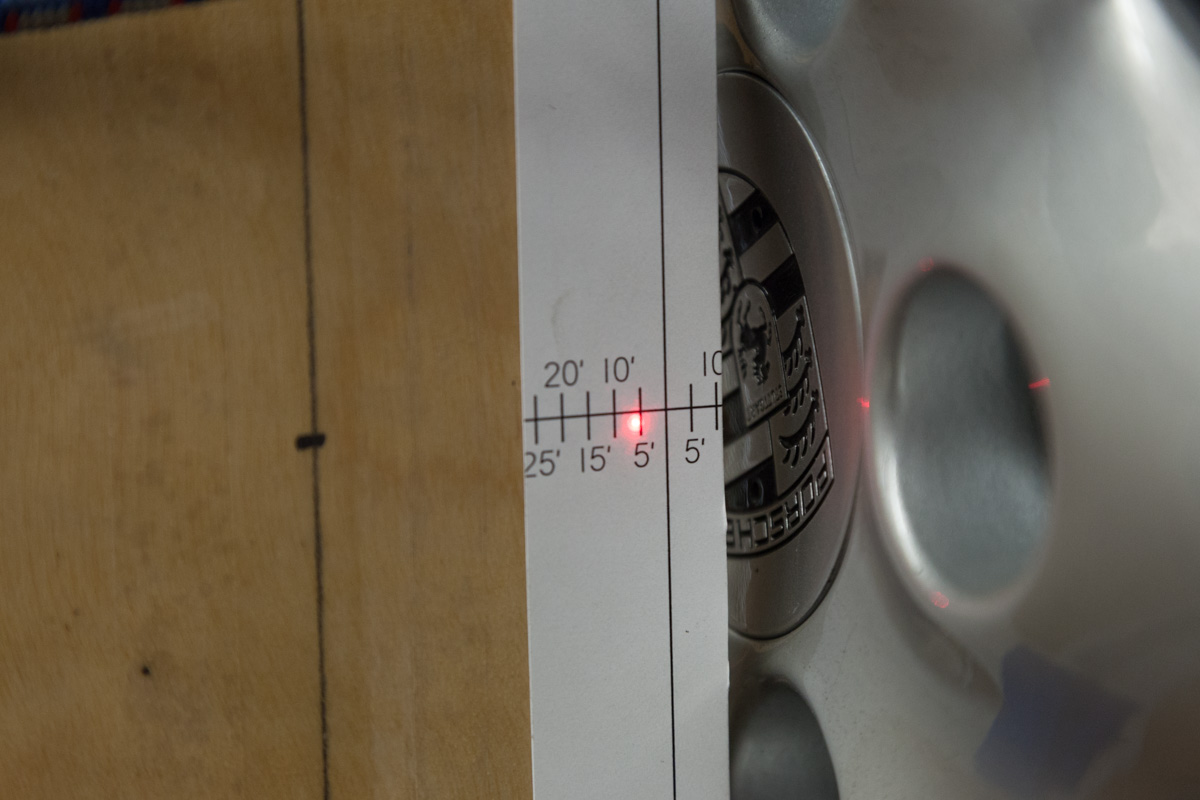
Here's a closeup of the target, showing about 6' toe-in for the right side. The scale is simple trig, wheelbase is 98.4" times the tan of 5' is 0.14" per 5' mark, 0.29" per 10' mark, 0.57" per 20' mark. That's a scale that makes it very easy to see exactly where you are at.
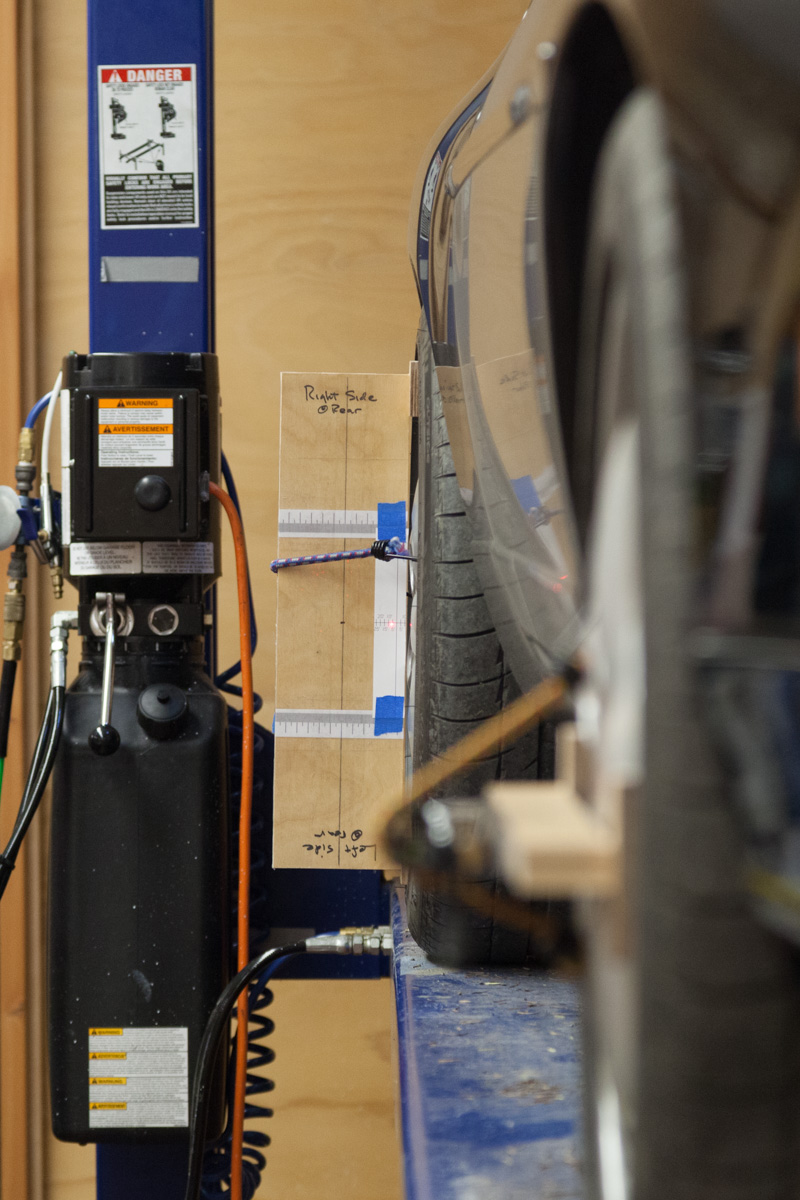
And here's a perspective of the whole thing. Doing this on a (4-post) lift really simplifies things, and this one (Bend-Pak) has adjustments on the locking rails for the four corners that allow leveling the ramps.
That's toe. For camber I flip the laser bracket vertical and either use the laser as a simple level, measuring how far the upper edge of the bracket gets pulled away from the rim for the level to indicate true vertical (drill bits make nice measurement gauges), or use a HF digital level that measures tilt in tenths of degrees (although somewhat imprecisely, being HF).
One thing that is important is to roll the car back and forth a foot or two after making any adjustments, otherwise you have the rubber tire arguing with the rubber bushings. Sitting the tires on something slippery also works (e.g. plastic bags), but I get a little nervous doing that with the car off the ground.
In the pics below I am checking the right-front wheel of our GTS, shooting the target at the rear wheel.
Here's the laser on the front wheel. I used plywood for the bracket, the steel bar stock is for the laser to stick to. Bungee hooks are covered with shrink-tubing, I need a better arrangement for that.
Here's the target on the rear wheel. The center line is where the target scale would go with zero offset front/rear, this is our GTS so the offset is large-- rear track is wider. For the S4 and GT it is only a few mm. The target offset would be reversed when shooting from rear wheel towards the front-- the backside looks the same except the offset is outwards, not inwards.
The "zero" line on the target is established by sitting both laser and target assemblies on any flat surface. Then measure the difference in "track" front and rear, i.e. difference in width between the outer rims, front and rear. I do this by dropping a plumb bob from the laser bracket at each wheel, marking the position on tape and then moving the car and measuring the tape marks. Half the difference is the target offset.
Here's a closeup of the target, showing about 6' toe-in for the right side. The scale is simple trig, wheelbase is 98.4" times the tan of 5' is 0.14" per 5' mark, 0.29" per 10' mark, 0.57" per 20' mark. That's a scale that makes it very easy to see exactly where you are at.
And here's a perspective of the whole thing. Doing this on a (4-post) lift really simplifies things, and this one (Bend-Pak) has adjustments on the locking rails for the four corners that allow leveling the ramps.
That's toe. For camber I flip the laser bracket vertical and either use the laser as a simple level, measuring how far the upper edge of the bracket gets pulled away from the rim for the level to indicate true vertical (drill bits make nice measurement gauges), or use a HF digital level that measures tilt in tenths of degrees (although somewhat imprecisely, being HF).
One thing that is important is to roll the car back and forth a foot or two after making any adjustments, otherwise you have the rubber tire arguing with the rubber bushings. Sitting the tires on something slippery also works (e.g. plastic bags), but I get a little nervous doing that with the car off the ground.
12-11-2015, 01:12 PM
#22
Rennlist Member
Thread Starter
Jim,
Excellent- I am trying to jury rig something along those lines as my approach for measuring total toe is quite difficult to setup accurately for each side.
Rgds
Fred
Excellent- I am trying to jury rig something along those lines as my approach for measuring total toe is quite difficult to setup accurately for each side.
Rgds
Fred
12-11-2015, 01:21 PM
#23
Rennlist Member
12-11-2015, 01:24 PM
#24
Rennlist Member
that set up is the next variation of my testing method. just take that plywood piece, but rotate the piece 90 degrees. drop two plumbobs one in front and one in back and mark the ground with a dot... do the other side. measure the distance between the two front dots and the two rear dots from each rim.
there.... that is your toe, in reality and very accurate ... the ONLY difference is if you dont like using the tire side wall, which is very true... you can measure the runnout of that as well. you dont use the budging area, so its as accurate as the rim itself.
there.... that is your toe, in reality and very accurate ... the ONLY difference is if you dont like using the tire side wall, which is very true... you can measure the runnout of that as well. you dont use the budging area, so its as accurate as the rim itself.
12-11-2015, 02:02 PM
#25
Chronic Tool Dropper
Lifetime Rennlist
Member
Lifetime Rennlist
Member
Jim--
I do the same thing, but use a pocket scale instead of the plywood standoff piece at the rear. The whole process is iterative, since changing camber front or rear moves the center cap relative to car centerline, as will changes in ride height. But we are definitely on the same page. I use the drill-bit spacing method with a separate bubble level to get camber numbers, with my laser fixture rotated to vertical. The second level is then just pressed (actually bungee'd or spring-clamped) to the fixture with the drill bit spacer at the top between them. Adjust until the second bubble is centered and I'm done.
Used plastic shopping bags make easy slip plates, when sprayed inside with a little PAM. I put a small 2x2 scrap behind each rear wheel to keep the car from sliding out of the garage when all four wheels are on the bags. The car moves almost too easily on them, particularly noticeable when tightening adjuster bolts for front caster and camber.
For front caster, I add the beam splitters that Fred refers to, and point the lasers down to the floor. Rotate the splitters to estimated front-to-rear, and tape a paper 30� angle 'template' so the beam lines up with the centered line. Then with the H-F angle gauge set to read camber, the steering is turned so the laser line matches 30� lines one way, grab the angle gauge reading, then spin the other way to 30� and get another reading. Caster is calculated from the difference between the two gauge readings. On the slippery bags, you can easily turn the steering right at each wheel.
And yes, Mark, it really is just like having our own alignment machine. Perhaps now you can appreciate why I look down on your stick-and-crayon method, when it's so easy to do it right every time with some simple setups.
12-11-2015, 02:07 PM
#26
Rennlist Member
that set up is the next variation of my testing method. just take that plywood piece, but rotate the piece 90 degrees. drop two plumbobs one in front and one in back and mark the ground with a dot... do the other side. measure the distance between the two front dots and the two rear dots from each rim.
there.... that is your toe, in reality and very accurate ... the ONLY difference is if you dont like using the tire side wall, which is very true... you can measure the runnout of that as well. you dont use the budging area, so its as accurate as the rim itself.
there.... that is your toe, in reality and very accurate ... the ONLY difference is if you dont like using the tire side wall, which is very true... you can measure the runnout of that as well. you dont use the budging area, so its as accurate as the rim itself.
Second, I am measuring each wheel separately relative to the car's centerline (as defined by the front and rear wheels). You are measuring the two sides relatively to each other but you have no idea where the wheels are pointed. For the front, you find out later whether the steering wheel is centered, but if the rear is off then you just crab down the road.
Which is all fine for a race car, but my experience is that road cars will benefit from more care and precision with alignment than is possible with either strings or the side-to-side measurements that you describe.
12-11-2015, 02:29 PM
#27
Rennlist Member
For front caster, I add the beam splitters that Fred refers to, and point the lasers down to the floor. Rotate the splitters to estimated front-to-rear, and tape a paper 30� angle 'template' so the beam lines up with the centered line. Then with the H-F angle gauge set to read camber, the steering is turned so the laser line matches 30� lines one way, grab the angle gauge reading, then spin the other way to 30� and get another reading. Caster is calculated from the difference between the two gauge readings. On the slippery bags, you can easily turn the steering right at each wheel.
Thanks, Jim
12-11-2015, 02:44 PM
#28
Chronic Tool Dropper
Lifetime Rennlist
Member
Lifetime Rennlist
Member
You can measure and calculate from any angle that's avalable from the steering really. It just seemed to me that the larger the angle (and therefore the difference between the two camber readings) the better chance I'd have of getting it right.
12-11-2015, 02:45 PM
#29
Rennlist Member
Two differences: I am measuring angle over a span of 98", while you are measuring over 17". As Dr. Bob pointed out, a longer measurement span means more precision so my method is 5.764 times better.
Second, I am measuring each wheel separately relative to the car's centerline (as defined by the front and rear wheels). You are measuring the two sides relatively to each other but you have no idea where the wheels are pointed. For the front, you find out later whether the steering wheel is centered, but if the rear is off then you just crab down the road.
Which is all fine for a race car, but my experience is that road cars will benefit from more care and precision with alignment than is possible with either strings or the side-to-side measurements that you describe.
however, mine,as i have NOT oversold, is only for checking or minor adjustments to toe. its not 17" its more like 25" and finding 1/4"is very easily to be accurately found and changed or measured to 1/8"..... there is much more slop in the system anyway, so that amount of accuracy is fine.
Yes,i will never be able to know the relationship of the rear vs fronts. thats where i get the hunter involved.
not an alignment machine good job... "check to see if im ok", good job
12-11-2015, 03:40 PM
#30
Rennlist Member
Thread Starter
Mark,
Happy to try anything but was struggling to understand your method. If I understand correctly what Jim has just posted your method measures total toe rather than the toe on each side. What I have done to date measures total toe but not each side which I have been eyeballing and used logic to correct.
Now if I can rig my lasers like Bob and Jim have I should be able to get a very accurate picture of what is happening toe wise. Camber is quite easy to read but caster is another matter altogether. I have basic understanding of the concept but how one measures it with the kit we have is beyond me altogether at the moment. I am going to have to study what Bob has written and see if I can get it to soak in.
Lifting the rear passenger side wheel has altered the rear end alignment at tad- camber seems a bit less - have no assessed the rear toe [yet].