When you click on links to various merchants on this site and make a purchase, this can result in this site earning a commission. Affiliate programs and affiliations include, but are not limited to, the eBay Partner Network.
S4 intake manifold: I made some changes ... dyno results ...
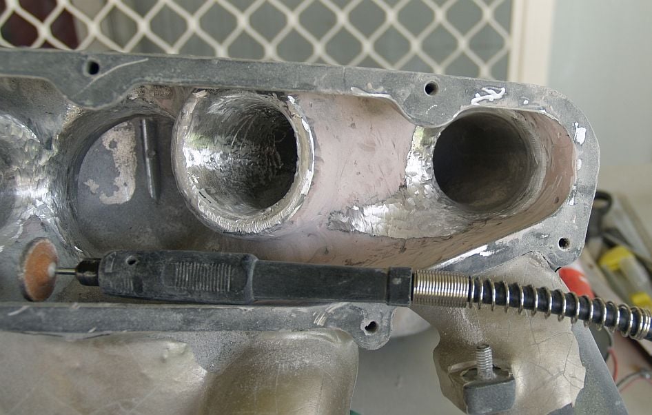
While my S4 manifold was out recently I made a few internal changes to reduce turbulence and inprove airflow to the bellmouths.
SOTP dyno said engine response was sharper from the bottom up and today I got some dyno results.
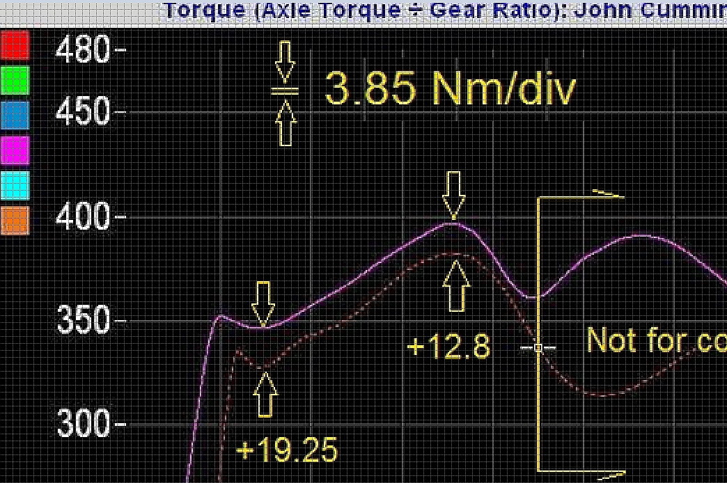
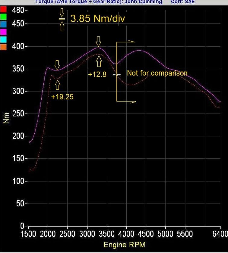
I've posted only the torque curves comparison.
Important point: at the car's last run on that dyno (John Gill. Rennlister), the flappy was inoperative, so a comparison with today's result is valid only up to 3800rpm (flappy opening point).
The chart verifys my SOTP conclusion and car is more fun to drive, engine now allowing quick throttle blips on downshifts.
Muahhh har har harrr harr harrrrrrrrr .... evil laugh while wringing hands .... Eeef I tole U I would haf to keeeel you ....
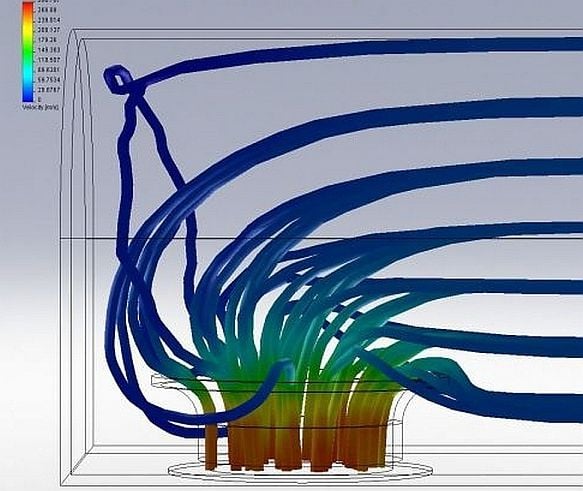
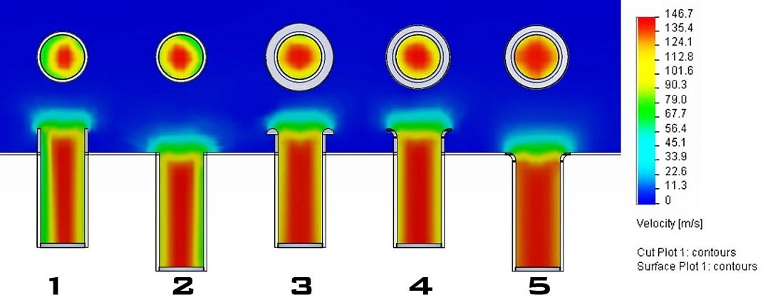
Oh alright then: they look quite over-the-top but when you look at CFD modelling of bellmouth intake flow they make sense. The models show that fast moving air is anything but well behaved and that what our eyes lead us to think is mostly far from the reality:
This is what is occurring around each bellmouth to varying extent:
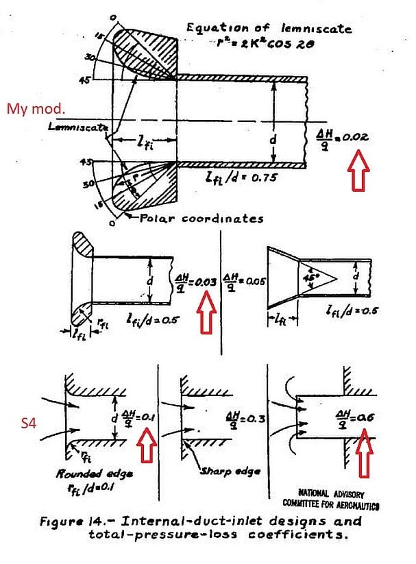
The 'shape' of the bellmouth is crucial:
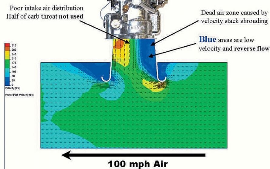
Airflow across a bellmouth doesn't help: applies to shrouded bellmouths in the manifold
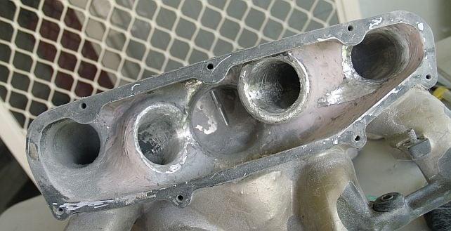
My manifold part way through:
Flaring the OE bellmouths:
Unfortunately in the rush to finish the job I forgot to get pics of the finished item. :-(
Here is anothe model showing bellmouth flow effiency vs the location of the bellmouth wrt a flat airbox floor:
I've made change in two other areas but this should do think about for the moment.
I also plan to insert a spacer under the LHS plenum cover. Close, but not ready at the moment.
That was the manifold with the dead flappy vacuum actuator (during that first dyno run).
There was also an Exxon Valdeez type oil leak at the base of the oil filler neck needing attention. Fortunately the wildlife casualties were limited a few driveway ants.
dead flappy, DOESNT effect full power at RPM past 5000 at all.. I know, because I did the dyno tests with and without flappy even installed, as well as flappy pegged open and closed.
so, is it safe to say , you gained HP from 5000rpm onward as well?
what was the registered max HP of both runs?
The benefits are pretty imaginary, if you are thinking that there will be differences in throttle blips..... that is wAYYY part throttle stuff. the only thing that you might see here is the WOT HP differecnes. (or torque differeces as shown by the graph) and who really floors the car below 2500rpm anyway.... I hope you don't!
the test is very valid for what is important... the RPM from 5000 to 6400. it looks like there are some decent gains there.
roughly, 10hp gained in the 5500rpm range?
what kind of dyno and software doesn't allow for the simple math of the HP to be shown??
Hey Mark, and with all due respect, did U actually read the detail of my post?
I specifically stated that the comparison between both runs was VALID ONLY UP TO 3800rpm I.E. WHERE THE FLAPPY OPENS !!!!!!!!!!.. because on the previous run the flappy was NOT working c/- a failed vacuum actuator and therefore the resulting chart was realistic only up to 3800rpm.
Flooring the engine under 2500 rpm? Where did I say anything about that?
Gently rolling on the throttle in say 2nd from 2000rpm and 20mph away from traffic lights is anything but abuse. And as the revs rise I roll the throttle a little more and so on.
Here's an observation: today - aircon on (100F summer here), my daughter in car, and the engine responds as well as it did with the 'old' manifold with no passenger and aircon off. And has done since I modded the manifold.
Regards.
Upfixen.
BTW - the changes I made didn't happen because I woke up one morning in a frisky mood. There IS a valid technical reason behind each change.
You made a number of changes there:
- Probably increased the runner flow coefficients
- Probably reduced turbulence at the back wall
- Shortened runners 6 & 7
- Reduced the plenum volume
- Increased the taper of the runners
Which ones of those do you think are responsible for most of the improvement?
If you ever get bored, open up the driver side plenum and take us photos of what you did there. In their stock form, the runners 5&8 are the worst above the mid range rpms so I'd expect a lot of gains from there.
I started out to understand body airflow aero stuff (Mythbusters golf ball car was a game changer), as well as turbulence generators and laminar flow and Reynolds numbers etc etc, and bit by bit I went from the macro to the micro, finally seeing the S4 manifold for what it really was: a victim of an inbred corporate engineering culture; and a panicked one at that. LOL LOL
Then I sort of stumbled across hobby applications of CF: what with the current range of urethanes, RTV silicones etc for proto modelling and saw how really easy it now was to bring a shape to life, so I decided to make my own intake manifold.
But ... but ... I couldn't bear the thought, as an engineer, of refitting that manifold with so many aero flaws, and so easily corrected, that I did what I did.
Cost me abt $50 in materials and quite a few man hours labour (but when is an engineer ever happier?) to translate the mental CFD images to real life contours.
From a theoretical perspective I had not a moment's doubt that I would see an improvement.
Most puzzling for me has been the next-to-non existent appreciation of the subject by almost all the "gun" performance engine builders.
I've posted only what I've changed in the upper plenums, but I've made two significant changes elsewhere which I'll be posting shortly.
I'm very impressed with PorKen's work re mapping the ignition advance per intake runner, or runner pairs. The results mimic my intuitive analysis of gas flow per runner.
IMHO the S4 manifold, when thoughtfully colour powder coated is a thing of beauty to behold, so if a way can be found to both improve it's performance while preserving it's artisan appearance then all for the better.
Wow, very interesting. But I wonder if you really have the case that air is flowing past a bell mouth at the same time it is flowing into it. I cannot quite see the total picture, but since the cylinders fire one at a time, I assume they intake one at a time. And, I assume that the intake runner does not serve as a significant capacitor so that no air flows into an intake runner when its piston is not on the intake phase.

 01-06-2015, 10:08 AM


 Eeef I tole U I would haf to keeeel you ....