When you click on links to various merchants on this site and make a purchase, this can result in this site earning a commission. Affiliate programs and affiliations include, but are not limited to, the eBay Partner Network.
Note it is the center cylinders that are the 'long' ones, 6&7, 2&3. The four corner cyls, 1458, are the noodly 'short' ones.
The pax/right plenum has the 6&7 horns on the outside. In the left plenum the 2&3 horns are on the inside. This might have something to do with the filling? 6&7 have effectively even longer tubes, including the plenum distance to the feed passage.
My bad, thanks for catching the error. I made some edits above.
Since the plenum cross-sectional area is so large compared to the runner cross-sectional area, it is my opinion that the location of the runner bellmouths within the plenum doesn't have a meaningful impact on the resonance tuning. That's just an opinion.
The location does matter in one sense, however. If the runners are at the plenum ends, air that is going to other runners doesn't flow over them. If the runners are at the plenum center, air going to other runners does flow over them. As we know, the static pressure that the runner sees goes down if the air flows over the runner opening at perpendicular angle. Therefore, it is conceivable that the flow to runners 6&7 cause lower pressure and worse filling of 1&4 and the flow to runners 5&8 cause lower pressure and worse filling of 2&3. Note that I am saying conceivable, not likely.
The above is just one of many hypotheses, and a difficult one at that to test on a flow bench. One would have to test the whole intake manifold with the throttle body bolted on, with the bench blowing from the throttle body. The flow would have to be measured with a velocity probe at the runner outlets (intake port ends).
If the 2&3 show worse exit velocity, one potential cure is to install spacers to the driver side plenum which reduces the velocity of the air flowing over the 2&3 bellmouths. Then, if desired, claw back some or all of the increased plenum volume by filling the plenum with epoxy behind the ends where it doesn't impact the 2&3 bellmouths. One should keep in mind that the worse exit velocity could be caused by many other things as well, however.
A lot of work there, again.
If you look at this thread here, https://rennlist.com/forums/928-foru...-spacer-2.html , there's some indications there that runner 2 works the best, not worst, throughout the rpm range: "He said #2 is the most efficient, moving the most air consistently throughout the RPM range." That makes me guess that there's something else going on in your setup than just 6&7 flowing well and 2&3 flowing poorly, as per those individual cylinder AFR measurements cylinder 2 overall fills the best. At this point, the cam timing being off a bit sounds a more plausible explanation to what you are seeing.
Results so far show that each plenum has a similar curve as before, but 4/7 and 5/2 prefer a bit less advance comparatively. Front to rear there are rpms where one group does better than the other here and there, though.
Right around 5850 rpm 5/2 does a deep dive compared to 3/8. This has always been a problem area for consistent max HP (5700-6100).
Once it is mostly knock free again I'll post a graph with all four groups overlaid. (Few more runs.)
I don't get it how 4 and 7 could move together with rpm, or how 5 and 2 could.
Looking at this from tuning perspective, in my opinion, it has to be that the 30cm runners work completely differently from the 20cm runners, depending on the rpm. There's really nothing as important to the shape of the torque curve as the intake manifold runner length. My thinking is that if any result shows that the four long runner cylinders don't move approximately together in terms of torque / cylinder filling and the four short runner cylinders also separately as a group, then there's something wrong either with the motor or the measurement.
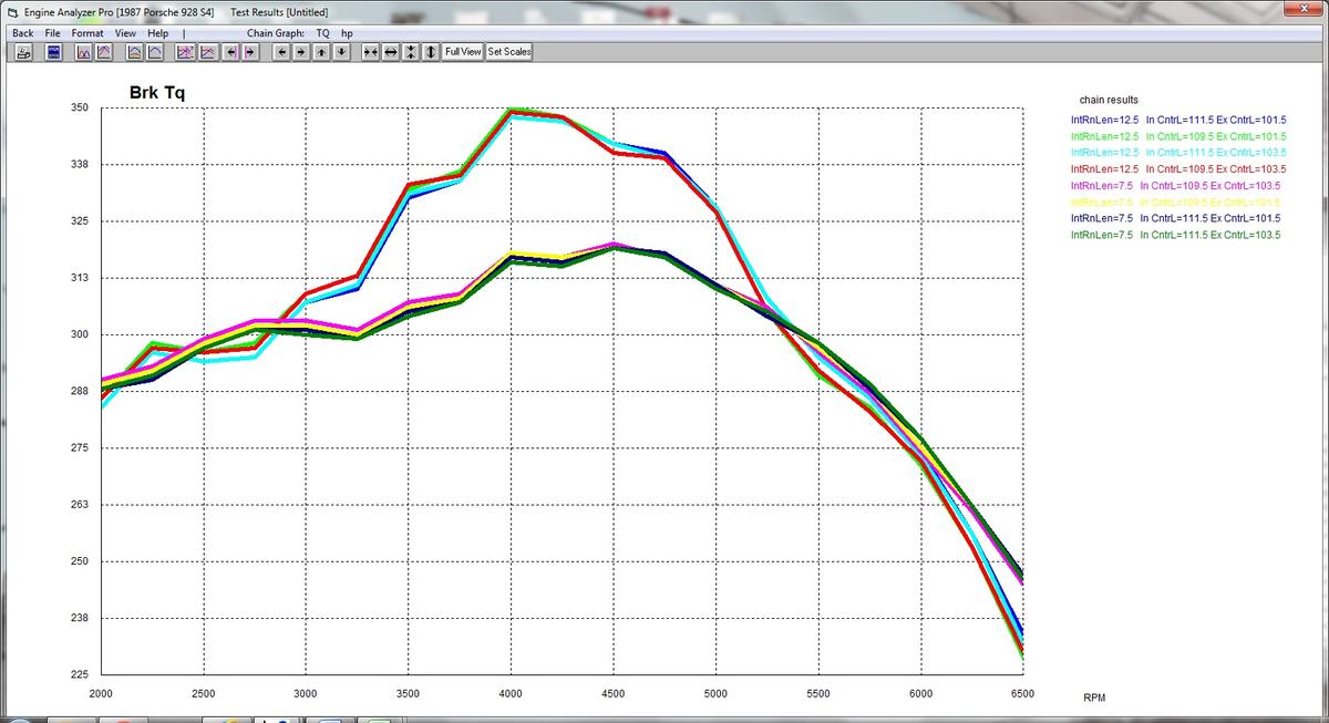
Here's an example S4 simulation from EAP 3.9 in which I vary the runner length from 7.5" to 12.5". I also vary cam timing by 2 degrees independently for both intake and exhaust to create a contrast. Things like a couple of degrees of cam timing are completely dwarfed by the difference between the long and short intake runners.
I don't get it how 4 and 7 could move together with rpm, or how 5 and 2 could.
That's how my code groups the cylinders for simplicity. (One map for each corner.) As I said earlier, it would probably be better to group the inner and outer cylinders, but that would be a bit more complicated to program.
It's most likely the 7 and 2 as you say. 4 and 5 are just along for the ride.
Tuomo, 20 & 30 cm tubes works same way, they are only working on different Helmholz resonance harmonics, but at same rpm level. The 30cm is working on 2th and 20cm on 3th,
the pulse strenght difference is arounf 3-4%, 2th being the strongest.
That's one of the tricks on S4 & up intake.
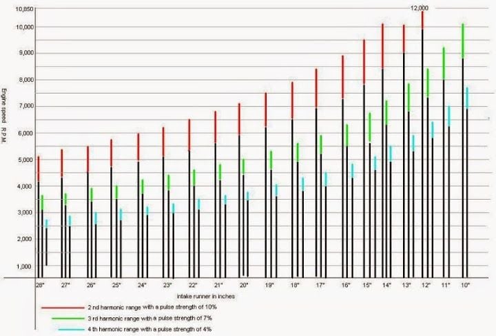
Found this from speedtalk:
As you will notice, any particular length will 'tune' at three different RPMs (still shorter ones will tune at four or more) Unfortunately,
midway between each tuning peak is a similar strength 'off-tune' valley, so unlike an exhaust system which can tune over a 2,000+ RPM range,
it is not possible to benefit over more than a 600-800 RPM range. Getting a wide powerband gain requires some kind of variable length system.
However, Louis Ott has mentioned that AFR difference is minimal between those two cylinder banks and therefore he's been using O2 only on one side.
Could this be related to different fuel pressure between the rails on each side? Could the dampers or pressure regulator cause something like this?
I've spent some time modeling these in Excel from first principles and confirming results in the EAP 3.9. Based on the results that I've gotten, I disagree with you. The short and long runners do not work the same way.
First point to make, which I am sure that you've taken into account, is that the intake tract length is the runner length plus 10cm in the head. So we're looking at a spread in total runner lengths from 11.5" to 16.5" in the extremes.
Second is that even if we take the Speedtalk.com graph at a face value, it's still the case that we have a major problem. The long and short runners match pretty well in the 5500-6500 rpm range based on the graph, even though as you say resonance orders are different. I can confirm that our experience is consistent with that, you can feed the engine sick levels of manifold pressure at that range with basically no knocks or other ill effects.
However, that's not the problem (or non-problem) I am interested in addressing. The problem is in the 3000-5500 rpm range where the long and short runners are hopelessly mismatched. The long runners hit a strong resonance point at 3500-5000rpm while the short runners got nothing worth speaking of. This is confirmed both by our knock limit estimates with turbos and Ken's "problem rpm range" in his graphs.
Since both banks have two long and two short runners, the AFR from both banks can be just right on average and lean in two cylinders and rich in two cylinders. I don't think the bank-to-bank AFR _alone_ can tell one too much about the difference between long and short runners. It would tell us something about cam timing if cam timing is wildly off.
Originally Posted by simos
Tuomo, 20 & 30 cm tubes works same way, they are only working on different Helmholz resonance harmonics, but at same rpm level. The 30cm is working on 2th and 20cm on 3th,
the pulse strenght difference is arounf 3-4%, 2th being the strongest.
That's one of the tricks on S4 & up intake.
Found this from speedtalk:
As you will notice, any particular length will 'tune' at three different RPMs (still shorter ones will tune at four or more) Unfortunately,
midway between each tuning peak is a similar strength 'off-tune' valley, so unlike an exhaust system which can tune over a 2,000+ RPM range,
it is not possible to benefit over more than a 600-800 RPM range. Getting a wide powerband gain requires some kind of variable length system.
However, Louis Ott has mentioned that AFR difference is minimal between those two cylinder banks and therefore he's been using O2 only on one side.
Could this be related to different fuel pressure between the rails on each side? Could the dampers or pressure regulator cause something like this?
The 3000 - 5500 range is where VE% is the highest as Intake/(Exhaust) velocities starts to work as well together with possible pulse tuning.
I did once some excercies with Pipemax to find S4 intake tube resonance points. The following values are calculated by using stock cams @ 6100rpm
Around 320hp, VE 95%
Calculations closely matches to standard S4 intake tube lenghts as you see below.
- Induction System Tuned Lengths - ( Cylinder Head Port + Manifold Runner )
1st Harmonic= 29,121 (usually this Length is never used)
2nd Harmonic= 16,528 (some Sprint Engines and Factory OEM's w/Injectors)
3rd Harmonic= 11,539 (ProStock or Comp SheetMetal Intake)
4th Harmonic= 9,082 (Single-plane Intakes , less Torque)
5th Harmonic= 7,369 (Torque is reduced, even though Tuned Length)
6th Harmonic= 6,199 (Torque is reduced, even though Tuned Length)
7th Harmonic= 5,350 (Torque is greatly reduced, even though Tuned Length)
8th Harmonic= 4,706 (Torque is greatly reduced, even though Tuned Length)
Note> 2nd and 3rd Harmonics typically create the most Peak Torque
4th Harmonic is used to package Induction System underneath Hood
Plenum Runner Minimum Recommended Entry Area = 1,673 to 1,882 Sq.Inch
Plenum Runner Average Recommended Entry Area = 1,924 Sq.Inch
Plenum Runner Maximum Recommended Entry Area = 1,965 to 2,325 Sq.Inch
- Induction System Tuned Lengths MM- ( Cylinder Head Port + Manifold Runner )
1st Harmonic= 739,668 (usually this Length is never used)
2nd Harmonic= 419,811 (some Sprint Engines and Factory OEM's w/Injectors)
3rd Harmonic= 293,084 (ProStock or Comp SheetMetal Intake)
4th Harmonic= 230,682 (Single-plane Intakes , less Torque)
5th Harmonic= 187,167 (Torque is reduced, even though Tuned Length)
6th Harmonic= 157,463 (Torque is reduced, even though Tuned Length)
7th Harmonic= 135,899 (Torque is greatly reduced, even though Tuned Length)
8th Harmonic= 119,528 (Torque is greatly reduced, even though Tuned Length)
Note> 2nd and 3rd Harmonics typically create the most Peak Torque
4th Harmonic is used to package Induction System underneath Hood
Plenum Runner Minimum Recommended Entry Area = 10,794 to 12,143 Sq.CM
Plenum Runner Average Recommended Entry Area = 12,410 Sq.CM
Plenum Runner Maximum Recommended Entry Area = 12,678 to 15,002 Sq.CM
Since tube lenghts are dependent on intake duration, here is calculation based on Stage II @ 6100rpm.
Little longer tubes needed or little more rpms to use stock intake lenghts. Other values used are 430hp, VE 105% Actually over 6500rpm needed if I remember right.
- Induction System Tuned Lengths MM- ( Cylinder Head Port + Manifold Runner )
1st Harmonic= 841,225 (usually this Length is never used)
2nd Harmonic= 477,452 (some Sprint Engines and Factory OEM's w/Injectors)
3rd Harmonic= 333,325 (ProStock or Comp SheetMetal Intake)
4th Harmonic= 262,355 (Single-plane Intakes , less Torque)
5th Harmonic= 212,865 (Torque is reduced, even though Tuned Length)
6th Harmonic= 179,083 (Torque is reduced, even though Tuned Length)
7th Harmonic= 154,558 (Torque is greatly reduced, even though Tuned Length)
8th Harmonic= 135,940 (Torque is greatly reduced, even though Tuned Length)
Note> 2nd and 3rd Harmonics typically create the most Peak Torque
4th Harmonic is used to package Induction System underneath Hood
Plenum Runner Minimum Recommended Entry Area = 12,476 to 14,036 Sq.CM
Plenum Runner Average Recommended Entry Area = 14,345 Sq.CM
Plenum Runner Maximum Recommended Entry Area = 14,653 to 17,340 Sq.CM
The 3000 - 5500 range is where VE% is the highest as Intake/(Exhaust) velocities starts to work as well together with possible pulse tuning. I did once some excercies with Pipemax to find S4 intake tube resonance points. The following values are calculated by using stock cams @ 6100rpm
Around 320hp, VE 95%. Calculations closely matches to standard S4 intake tube lenghts as you see below.
Yes, the pipes match between 5500-6500 rpm. Not challenging that. All I am saying that at 3000-5500 rpm the intake manifold is f'd up like my wife's checkbook.
Yes, the pipes match between 5500-6500 rpm. Not challenging that. All I am saying that at 3000-5500 rpm the intake manifold is f'd up like my wife's checkbook.
^^^^^^^^^^^^ Very funny!
Unless a manifold has variable runner length (993 style manifold) the runner lengths are always going to be a compromise.
I tend to think that Porsche Engineers were probably a whole bunch smarter than we give them credit for.....and it isn't just a coincidence that the runner lengths are conveniently a multiple of the intake pulses.
I believe (and have believed since the very first day that it was made) that the "Gates Racing Belt" needs some serious research in order to asertain its affect on the cam timing.
I can easily envision that the stock belt's stretch in regards to both static timing, heating of the engine, and high rpm cam timing was carefully researched and that substituting in a belt with completely different characteristics of stretch could not possibly have the same results.
I'm guessing that at higher rpms (as well as higher temperatures), the effective cam timing gets more and more retarded with the stock belt.
I find it very doubtful that a belt with significantly less stretch will provide the same results.
I've always thought of the stock cam belt as an "early version" of Variocam....and the Gates "Racing" Belt as stronger, but probably not appropriate for racing.
No gaps in power a-n-y-w-h-e-r-e and it never seems to run out of breath (to 6600 ).
Still learning a bit on the right side, but it's almost clean. Different temps and load.
Note 4/7 goes south over 6300 where the others don't.
Relative maximum full throttle ignition advance, front and rear of right and left plenums.
Ken,
You never cease to amaze me. I presume you have managed to create a software method to create sequence firing across 4 banks of two cylinders if I understand your posts correctly. Quite a difference of advance in the mid range bank to bank timing by the look of it and you could almost get away with 2 sets of 4 if you could tune out that top end end drop presumably not possible if resonance induced].
It would be very interesting to see a dyno chart of stock timing, linear optimised timing and this set up back to back as it were. This tells me that my difficulties are somewhat understandable/predictable consequences of the inherent design.
Even more interesting if you/John can work this coding into the ST2 programming somehow.
Unless a manifold has variable runner length (993 style manifold) the runner lengths are always going to be a compromise. I tend to think that Porsche Engineers were probably a whole bunch smarter than we give them credit for.....and it isn't just a coincidence that the runner lengths are conveniently a multiple of the intake pulses.
I believe (and have believed since the very first day that it was made) that the "Gates Racing Belt" needs some serious research in order to asertain its affect on the cam timing. I can easily envision that the stock belt's stretch in regards to both static timing, heating of the engine, and high rpm cam timing was carefully researched and that substituting in a belt with completely different characteristics of stretch could not possibly have the same results. I'm guessing that at higher rpms (as well as higher temperatures), the effective cam timing gets more and more retarded with the stock belt. I find it very doubtful that a belt with significantly less stretch will provide the same results. I've always thought of the stock cam belt as an "early version" of Variocam....and the Gates "Racing" Belt as stronger, but probably not appropriate for racing.
The imbalances of my wife's checkbook and of the mid-range resonance of the S4 intake manifold are both established facts at this point.
I think we now understand exactly what the designers wanted with the S4 intake manifold and why they did what they did. It all makes sense for what they were trying to do. They did rely heavily on the knock retard function and on the catalytic converters, but that allowed them to get a pretty flat torque curve without variable valve timing.
On cam timing: Thinking about magnitudes, I just don't see the belt stretch being a factor in cam timing to the point that it could make any difference, for either version of the Gates belt. In particular, the load on the belt between cam gears is relatively low, so I don't think the belts make any difference on the relative cam timing between banks. I can't prove this, it's just my sense of the magnitudes.
The engine heating up has a meaningful impact on the relative cam timing. As the block heats up, it expands. The expansion pulls the cam gears further apart and changes the cam timing. I did the math some years ago and I was able to match Porsche's cam timing difference spec with the temperature change between cold and running engine and the Reynolds 390 thermal expansion coefficient. I don't know if I could redo the computation, probably would have to take two measurements (distance between the cam gear centers between the banks, the radius of the cam gear), google the thermal expansion coefficient for Reynolds 390 alloy, and scratch my head for a little. In any case, when I did that computation some years ago, I was able to convince myself (but not necessarily others) that the Porsche spec for the cam timing difference simply matches the thermal expansion of the block and there probably weren't any other factors that they thought were important.
I presume you have managed to create a software method to create sequence firing across 4 banks of two cylinders if I understand your posts correctly. Quite a difference of advance in the mid range bank to bank timing by the look of it and you could almost get away with 2 sets of 4 if you could tune out that top end end drop presumably not possible if resonance induced.
Was this with or without plenum spacers?
Individual timing for four groups of two cylinders, yes. Knocks are recorded in 'permanent' memory in real time so the next time that (individual) engine is at that rpm, a little bit less advance is used. Eventually, all four groups will be a degree or two under their knock threshold, which should be ideal(-ish). A total of 512 cells...vs the original 16 static ones. �Qui�n es m�s macho?
I could go to per cylinder maps if I use half the rpm divisions - the limitation is in the permanent memory, there's plenty of EPROM space in the EZK for static, base maps...hmmm, I could make eight x 64 cell base maps and have eight x 32 cell learned maps...V2.0...
Timing advance tries to optimize the burn rate of the fuel/air mix. If there is more of the mix or better swirl (et cetera, et cetera) there is less need for advance as the mix will burn at a faster rate. The valleys above are hopefully where the best conditions for combustion occur. The peaks aren't terrible though, if you can put in enough advance to burn as much as possible before the exhaust valve opens. (As a side benefit, it is quieter, too.)
No spacer(s) yet. It would be nice if a spacer will let the left side pack more mix in through the mid-range. The ~24� difference in timing at ~4000 above is a little embarrassing for the S4 manifold?
Gone are the days where I hoped it would take another 2� advance at the top end to squeak out another 10 hp. There is a ~10� difference on those maps at 5850...I think it may do well on the dyno.
[I]I could go to per cylinder maps if I use half the rpm divisions - the limitation is in the permanent memory, there's plenty of EPROM space in the EZK for static, base maps...
I'm enjoying the back and forth immensely even though you guys are way WAY over my head here, but is it not possible to replace the original EPROM
with a higher capacity or even a faster chip? BTW, I'm not a hardware or software engineer so it may be a dumb question to you guys.
I'm enjoying the back and forth immensely even though you guys are way WAY over my head here, but is it not possible to replace the original EPROM with a higher capacity or even a faster chip?.
The EPROM/chip is not the problem. There's thousands of bytes available on there, especially on the EZK, which doesn't have a lot of code, compared to the LH. (It is essentially a high speed egg-timer.)
For my use, I want the EZK to adapt over time, so I need semi-permanent RAM, but there is only 256 bytes of (battery maintained) StaticRAM on the board. Of that, half of the SRAM is cluttered with diagnostic variables.
I'm not sure if the (8032=8051) processor could access the extra bytes if a larger capacity, 512, 1024 SRAM chip was soldered in...

 12-21-2014, 01:33 PM


 ).
).

