When you click on links to various merchants on this site and make a purchase, this can result in this site earning a commission. Affiliate programs and affiliations include, but are not limited to, the eBay Partner Network.
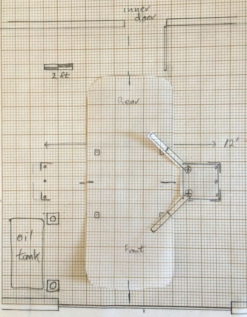
I've ordered a MaxJax, driven by fear of the motor mount rabbit hole. But I've got other vehicles ranging from my wife's SmartCar to a F150. For now, I'll put it in the workshop in the back of my studio; perhaps I'll build another garage next year. It has 10-foot ceilings, but I wish I'd made it longer, or put the inside door elsewhere. Anyway, here is my sophisticated engineering analysis of where to drill the holes:
The twist is that there are radiant heating tubes in the concrete, running vertically along the major grid lines, 12" OC (I took photos during construction; they are tied to 6" steel mesh). I'll only be using the three outer bolts; the margin of error is too small to drill for the inner two bolts. Danmar's analysis is for just these three, and shows a 400% safety factor for a 3000 lb load (one post). I might use shallow bolts for the inner locations, to keep the posts from rocking. As a former metallurgist, I'm not comfortable with the statistical nature of brittle failure, but I'll take a pill or something. I don't know how guys in earthquake zones work under cars.
The spacing is 145.6 inches, measured from the outer edges of the plates. That puts the holes half way between the tubes - in theory. I've read the extensive thread from 2009, where DrBob settled on 135 inches. I could do that, although 133.6 inches would be safer. I'll have bolts left over, so I could do both.
Seem reasonable? I'll need a rolling chair. I have a helmet. Best of all, I have four months of darkness and cold in a garage with radiant heat (unless I do something stupid).
This is what I did... been very happy with the setup whereby LED lights move around with the rolling chair... lifting up the Chevy pick-up, 928 and MB sedan.
So we've moved since the original placement, and in the new workspace I went a tad wider with the outer placement. Goal is to be able to open the doors as wide as possble with the car on the lift, yet have the arms near midrange length so car placement between the columns is not as critical. The inner holes placement is exactly one set of bolt spacings inward so I can some holes. Your F-150 will lift from the frame. well isnide the door sills, and may need the columns closer together so the arms will reach. To lift K's 4Runner for instance, I place one column on the closer set of holes.
To add to the excitement, the new workshop has porcelain tile flooring, so drilling and setting was a little different this time. I elected to have a local concrete saw-and-drill contractor do the work. The tile and mortar are drilled 1", and the concrete underneath has 7/8" holes for the WedJit anchors. I set the anchors deeper so there's no risk of drawing up on the tile, so have to use longer bolts. The 1" holes in the tile allow me to use almost-flat plastic chassis plugs (electrical item) to block the holes when the column isn't mounted. There's a full-sized PDF of the drill pattern available if you can PM your e-mail address. Note that the hole spacing is --almost-- 6" centers, so if you can locate the first holes successfully in your 6" grid, the others should be fine.
I'm at 132" on my maxjax, which works just fine for a 928, my Honda Odyssey, and my wife's CLK550. at 145" I think you're going to be near (beyond?) the limit of the arms' extension for a Smart car.
Good points. Seems like 133.6 and 145.6 will be useful spacings.
I got the plate drawing from Dannmar earlier. After accounting for the width of the holes, width of the radiant heating tubes, and how well I know where they are (+/- 2 inches? not sure), it becomes a nail-biter to drill all five holes. Fixing a gusher would require a jack-hammer and a plumber, and would leave behind an unsound concrete repair, unless ... nope, not feeling lucky about this.
So much depends on where the lift pads contact each car you plan to lift. And how much walk-around room you need outside the columns when the the lift is in use. The 928 has pads at the ends of the rocker sills, so fairly wide and well-centered to support the car with CG centered between the columns. Our late Honda Pilot has lift points just inside the running boards at either end of the sills, but weight is biased forward a few inches of the mid-point between the lift points. So the front arm needs to be about four inches shorter than the rear when lifting correctly. K's 4Runner lifts from frame rails almost a foot inside the running boards/rocker sills, and is nose-heavy. The columns need to be closer together, and I end up with rear arms almost fully extended, front arms ust a coupl inches shorter to pick up crossmember tie points. Moral of the story is that you want to plan the column locations with your target audience in mind.
At least as important will be how much room you'll need front and rear of any lifted vehicles. If the garage door will be open while a car is on the lift, look at where the door goes. If you need walkaround space at the garage door end of the car, plan for that early. There are times when I might be working on the south end of the northbound car, so make sure everything you look at/plan considers having each subject car face the other way. When working with the architect on my new garage, I kept moving the door out for that clearance. He would then expand the house interior to use the 'new space'. I finally 'splained that he could move that interior wall, but it could be no closer than 28 feet from the finished inside face of the garage door. I added some plan view examples of cars in the garage spaces, with required walk-through space. Finally showed him that there needed to be room for three full-sized SUV's, with walk through at both ends, workbench space, plus room for engine removal at the inner end. He still argued. My checkbook, my rules; so we have the space.
What you need is some super-duper Doppler ultrasound probe like the vascular surgeons use to check blood flow. Turn on the pump for the radiant heating, and map out where there's flow by Doppler.
Good points. Seems like 133.6 and 145.6 will be useful spacings.
I got the plate drawing from Dannmar earlier. After accounting for the width of the holes, width of the radiant heating tubes, and how well I know where they are (+/- 2 inches? not sure), it becomes a nail-biter to drill all five holes. Fixing a gusher would require a jack-hammer and a plumber, and would leave behind an unsound concrete repair, unless ... nope, not feeling lucky about this.
I feel your fear.
That said, you said you had pix of the installation - any chance you have excellent reference points for precise measurements, assuming the tubes are laid in straight lines? Even if it requires, say, exposing some framing to find a starting point.
Gusher? The hot fluid in those tubes isn't going to be under a lot of pressure, is it? If not, an in situ repair might be possible. Or, depending on flow pattern, perhaps a single cut tube could be blocked. If, for instance, they're fed from a manifold rather than a single, looping tube. Have you talked to the plumber/contractor who installed your hypocaust?
I like the doppler ultrasound idea, but perhaps your best bet will be to get a scissors lift or the like.
You should see the elaborate photographic and dimensional documentation I have for those tubes - I erected the partition walls myself (this is a ten-room, 40x60-foot building), and personally shot the plate nails down into the concrete. The nearby wall should be precisely centered between two tubes. But Euclidian geometry is suspended when I do carpentry; it could be off by an inch or two, or three. I should study my documentation - maybe I should be more confident.
Vein mapping - that brings back unpleasant memories. It might be easier to detect the mesh - no, there are two layers; the tubes were tied to the bottom layer. The upper layer is not aligned with it. Some exploratory surgery might be a reasonable procedure, in the proverbial inconspicuous location.
There are two loops in the workroom; losing one would not be catastrophic. Fixing a punctured tube would mean an excavation large enough to get a PEX tool into, with enough tube exposed to maneuver an insert into position - PEX is stubborn stuff. I wouldn't attach a lift anywhere near the repaired area.
I'm not worried about using only the outer bolts. The derate from 6000 lbs is probably quite small, and certainly good for 3500 lbs. Not sure about the F150, though.
I once determined the location of embedded electrical heating wires by dampening the surface then turn on the heat and watch the moisture evaporate. Drill where it dries last.
I once determined the location of embedded electrical heating wires by dampening the surface then turn on the heat and watch the moisture evaporate. Drill where it dries last.
Very clever! I was about to suggest infrared photography (relatively cheap, I believe) but this is the coolest idea so far.
Another idea I would not dismiss is, if all else fails, do consider a scissors lift. I am completely happy with my Bendpak MD-6XP.
And finally, you point out something I have brought up a number of times here and over on GJ- very carefully consider your lift points vs. the lift's ability to accommodate them. Manufacturer/distributor drawings saved me from making a very bad choice when I bought my lift.
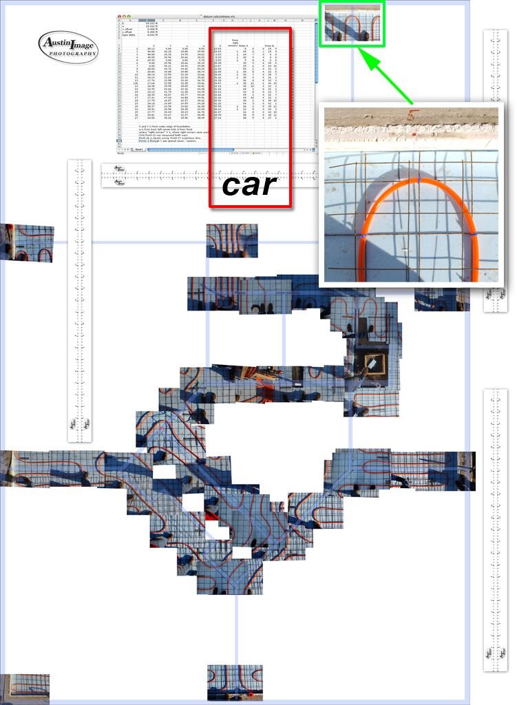
It's so hard to remember what I did 10 years ago, and to find the computer files after so many disk failures and new computers, but success!
This is my big composite of my slab. You can see how the tubes were arranged to avoid the partitions, sometimes routed through doorways. (A 5-inch slab avoids this trouble.) The important bit is Point 5 (inset), where I would/should have centered the wall. But I can reference the foundation also, and also the point at the other end of the wall. The table in the composite has their locations (based on triangulation blah blah blah). I see they differ by an inch, left to right ....
It will still be a nail biter. Thanks for all the interesting ideas.

 12-02-2014, 12:46 PM