When you click on links to various merchants on this site and make a purchase, this can result in this site earning a commission. Affiliate programs and affiliations include, but are not limited to, the eBay Partner Network.
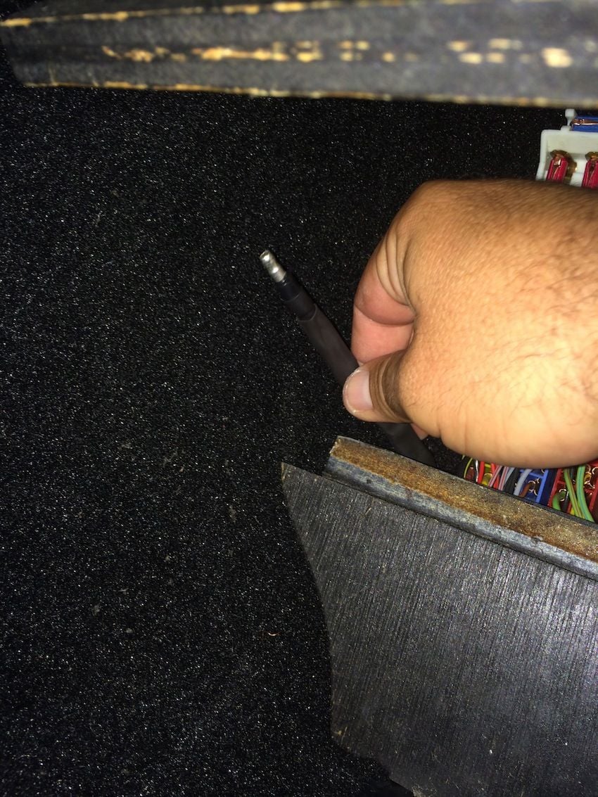
Well, I was removing the O2 sensor to replace it with a new one. The white plug near the CE panel (attached to green wire) was so brittle that it cracked when I unplugged it.
So my question is, can I solder in a new (or used) plug or do I have to replace the full length of the wire in the harness. The wire itself looks to be in good shape.
Another though was to JB weld the crack in the plug but I think soldering in another small length of wire with a good plug on the end is probably cleaner and more solid.
I picked up a new rubber insulated bullet connector at the electronics shop. Brought it home and started the white connector replacement.
When I picked apart the green wire connector ( male end of connector attached to harness) I found that it is "braided" ( one insulated wire wrapped around another insulated core wire), like co-axial. The outter wire doesn't seem to be connected to anything within the white connector. I expected it to be soldered to the metal part of the connector, but it isn't. At least not anymore. It just terminates within the plastic connector. The inner core wire is soldered to the metal bullet.
On the other end, I opened the female side of the connector ( black wire from O2 sensor) and found that this is just a single core wire, not braided.
So now my question is, do I solder core wire to core wire and leave the outter green wire insulated but disconnected? Or do both green wires (inner and outter) get connected to the black wire from the female side?
Any input is appreciated. Surprised no one has chimed in, from the people I've spoken with so far, this seems to be pretty common, although none of my thread searches have revealed any connector repair
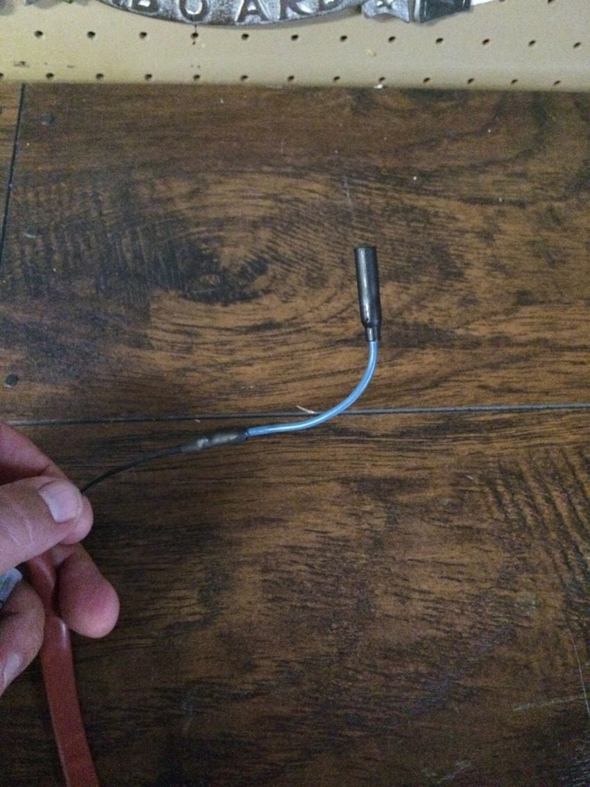
Well, in the end, for lack of better advise, I soldered in an insulated bullet connector as seen in pics. I tried to keep as much of the insulative-outer green wire intact and insulated between each layer with shrink. So as it turned out, the core wire solder joint was shrinked, then the outer wire shrinked, then the whole thing shrinked again just for good measure.
Car seems to run fine. Hardest part was getting the rubber body seal in the darn hole, but a little dab of clean motor oil along the grommet did the trick.
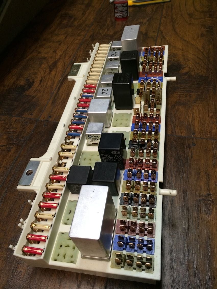
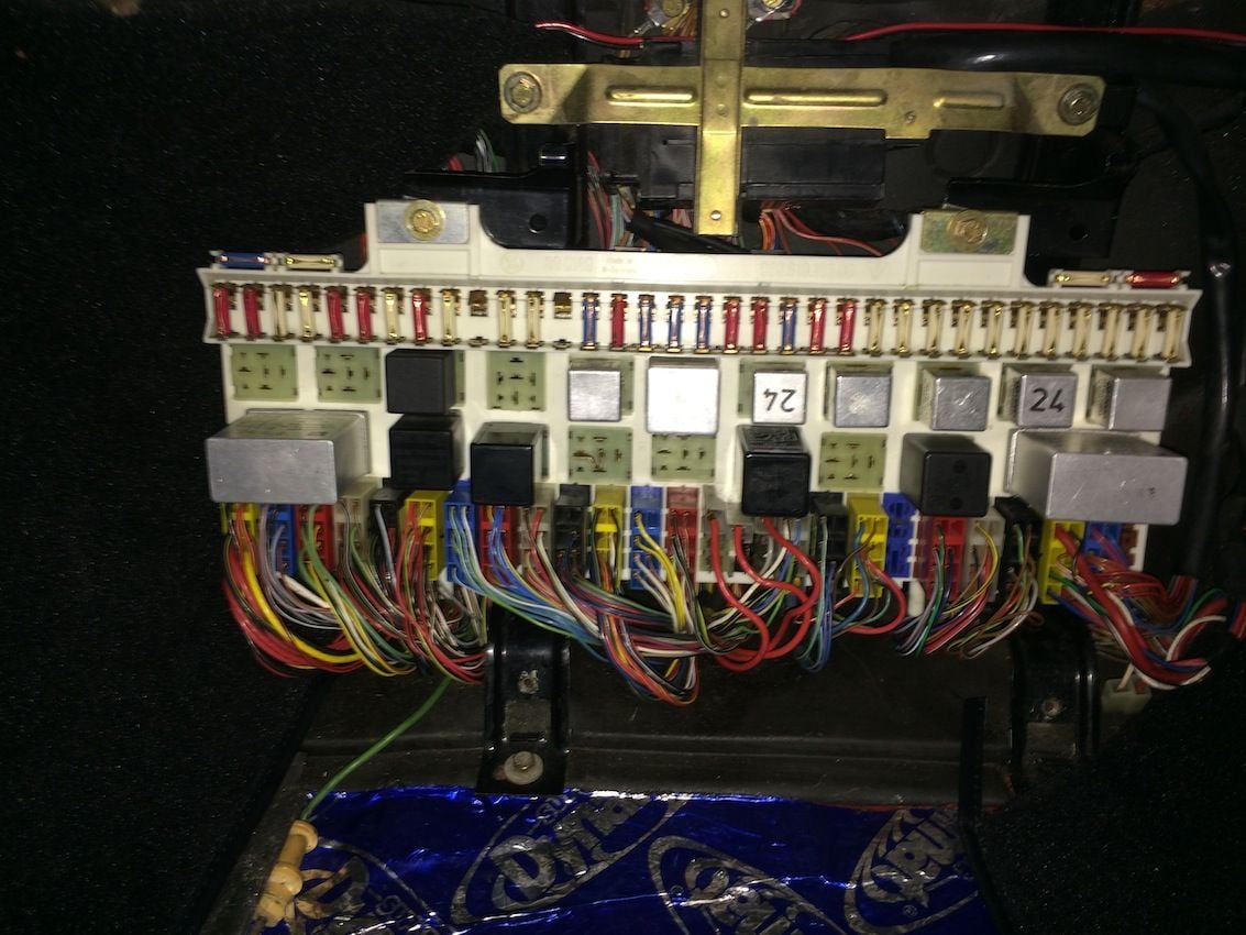
In an attempt to hichjack my own thread for the sake of adding more pictures; this O2 sensor was the last thing to do in my CE Panel area refresh. All tabs were removed, polished, replaced and deoxy'ed. All new fuses, all relay contacts polished and deoxy'ed. Also cleaned the grounds above CE and buttoned it all up with the wood cover and fresh new carpet. Sweet. Another case closed.
The CE panel looks great, and thanks for the description of your repair to the O2 sensor lead. My white connector is sound, but if I ever need to repair it this will be a big help.
Wish I would have noticed this sooner, you are never supposed to soldier the signal wire of an O2 sensor. Crimp only. It has to do with how the O2 sensor samples the fresh air inside the insulation. Here is a good thread on it and why you really shouldn't solder anything vs crimping: https://rennlist.com/forums/944-turb...sor-wires.html
Lol! Well I guess I'll know where to start if I have issues. Plenty of slack in the line, won't be hard to cut out the solder joint and recrimp. Thanks HP
I've read several thrrads and articles on this oxygen molecules in the wire theory, even on Bosch's site but I have a hard time beleving this theory. The wire is shielded to keep epectrical intereferance to a minimum but if the oxygen molecules are beeing sampled, why is the cable shielded? And how fast do these molecules travel up the cable? The cable is pretty air tight.
Any updates on how your solution is holding up, Ladybug83? Mine fell apart on me today, and because of how difficult it was for me to find any threads on the subject (yours being one of the better ones), I created a new thread with more keywords in the subject and linked back to this thread as well.
Here is the thread I started with questions about how we can address (and whether we need to address) this problem, since I believe it is or will be prevalent: https://rennlist.com/forums/928-foru...l#post12765282
So far everything seems to be good with this repair. Car runs great. Passed smog with flying colors. Haven't seen any issues that might be o2 sensor related. Thanks for making a more searchable thread. Looks like you've done a lot of homework. I wasn't able to find much at all when I did my search so kudos to you and good luck with your repair. Sounds like crimping is the way to go on this one, but my solder fix seems to be ok so far.
Wish I would have noticed this sooner, you are never supposed to soldier the signal wire of an O2 sensor. Crimp only.
It has to do with how the O2 sensor samples the fresh air inside the insulation.
Originally Posted by Imo000
I've read several thrrads and articles on this oxygen molecules in the wire theory, even on Bosch's site but I have a hard time beleving this theory. The wire is shielded to keep epectrical intereferance to a minimum but if the oxygen molecules are beeing sampled, why is the cable shielded? And how fast do these molecules travel up the cable? The cable is pretty air tight.
From what Ladybug83 found, there are two different types of wires on either side of the brittle connector. On the O2 sensor side, the signal wire is not shielded, however, on the computer side, the green wire has shielding, and seems the only one shielded. However, Ladybug83 said the O2 side wire was a solid conductor, and I read where the sampling occurs through the strands of a stranded conductor, so I still find it confusing as well. (Edit: clarified by Josh/Ladybug83 in the next post that the wire is actually stranded, so the confusion has been cleared up!)
Originally Posted by Ladybug83
So far everything seems to be good with this repair. Car runs great. Passed smog with flying colors. Haven't seen any issues that might be o2 sensor related. Thanks for making a more searchable thread. Looks like you've done a lot of homework. I wasn't able to find much at all when I did my search so kudos to you and good luck with your repair. Sounds like crimping is the way to go on this one, but my solder fix seems to be ok so far.
Good to know - thank you!
Last edited by hernanca; 11-24-2015 at 03:48 PM.
Reason: Clarification.
From what Ladybug83 found, there are two different types of wires on either side of the brittle connector. On the O2 sensor side, the signal wire is not shielded, and then the green wire on the computer side is the only one found to be shielded. However, Ladybug83 said the O2 side wire was a solid conductor, and I read where the sampling occurs through the strands of a stranded conductor, so I still find it confusing as well.
Good to know - thank you!
Carlos, let me clarify. Because Im new to cars, electrical systems, etc, I used the wrong terminology when I was describing the wires. When I said "braided", I meant shielded. When I said "solid core", I meant un-shielded.
The black signal wire coming from the O2 sensor is a stranded wire, but not shielded.
Also, a question for the experts in light of Carlos' diagrams. When I took apart the green wire white connector, I found that the core wire terminated to the metal bullet, but the shielding wire terminated to nothing within the white connector. If this shielding wire is connected to common grounds, wouldn't this leave an open ground?
Josh
Josh,
Thank you for the clarification! Do you recall whether the shielded wire also had a stranded core? I want to clean up my description in the other thread.
Re: your question. I don't know the answer, of course, but I did a quick search on shielding and grounding and found some mention of the dangers of "ground loops" when both sides are grounded, but it was over my head. As a layman and also new to electronics, I would say the setup is OK because it is insulated - it is not a wire dangling which could make contact with something. Interestingly, the shielding can work in both directions - it can also be used for protecting external components from something being generated inside the shielding!
Last edited by hernanca; 11-24-2015 at 03:50 PM.
Reason: Clarification.

 07-21-2014, 12:51 PM