
My 928 Projects Master Thread
 02-09-2014, 07:41 AM
#31
Addict
Rennlist Member
Rennlist Member
Thread Starter
If a 4.0:0 differential ratio was used, that ratio delivers,similar ratios in some gears to the 928 GT gearbox. First is a little taller around 10% taller, and the following speeds are possible with max revs,
1st=112 kph
2nd=164kph
3rd=219 kph same ratio or very close as the 928 in 3rd.
4th=263 kph
5th=320kph
6th=385 kph this is the same as 5th in the GT
It appears to be a great box to set bench mark times in, no gear change to 100 kph or 62 mph and one gear change to 160 kph or the old ton.
I went through the workshop manual to have a look how they set the depth of the pinion and while the exact same method probably can't be used on the Tremec the fact that the transmission has the split in the case where the 928 attaches may provide the flexibility to move the pinion back and forth relative to the crown wheel by means of spacing shims. The trick will be getting the pinion placed in the correct position so it can be shimmed, lots of careful measuring ahead.
 03-07-2014, 08:36 AM
#32
Addict
Rennlist Member
Rennlist Member
Thread Starter
So the flow sample valves were ordered today, I also spoke to the head porter and we discussed valves sizes. We agreed not to do too much development, I advised I have sectioned the head and that most work needs to be done on the exhaust side from where we are presently in terms of head flow.
I like to bench mark how we compare to other current state of the art or close to state of the art engines. I firstly look at valve to bore area. The recent (I don't know what the current 991 series uses) GT3 Cups cars use a 102.7 mm bore with 42 mm intakes and 36.4 mm exhaust valves. This chamber is very similar to the 928 chamber and has the same included angle. The Cup Car has intake valve area of 33.45% and exhaust valve are of 25.1%
If I use the planned 108 mm bore with 44 mm intake valves (If they fit) I will have a intake valve area of 33.2% and I also ordered 37 mm exhaust valves and this equates to 23.5%. I believe 44 mm may be the maximum, so no more area can be gained and the exhaust is down quite a lot. I did order 38 mm (6 mm stems) for the exhaust but they were later advised to be out of stock. If 38 mm are used we have 24.76% which would be good enough I think. However we will use the 37 mm valves for development.
I also have the flow figures a 996 GT3 Cup head @28" of water;
..........Intake...............Exhaust
0.050"...55.4..................43.4
0.100"..103.4.................97.7
0.200"..205.6................190.0
0.300"..289.2................238.8
0.400"..329.3................266.0
0.500"..344.0................282.2
0.550"..346.8................288.3
So in comparison to my head, these numbers are not as good on the intake but quite a lot better on the exhaust side. So I hope on the exhaust side there is enough material to get these higher numbers. I actually need to exceed these exhaust flow numbers.
The other aspect of the valvetrain is the camshafts, it is interesting that Porsche has used both hydraulic and solid lifters in their cup car engines. Again I don't know but may find out this GP weekend what the previous series of 997 Cup cars used. As I have mentioned I will use hydraulic tappets for ease of maintenance and hopefully they will be a bit easier on the valvetrain parts.
The machinist who is making the vast majority of parts will also make the cam billets. A lot of thought needs to go into these particular parts, I am no expert here, designing a multi piece camshaft will be a task. I think that the intake cam must have a adjustable sprocket. This is of course a required to set the optimum LSA.
If the exhaust cam is made adjustable or at least have a replaceable sprocket the risk is that there may be some "slack" and the 2nd part of the cam may be slightly out of sync with the front part of the cam. It would also make the gun drilling more expensive I would guess. The gun drilling for the short shafts or two shafts making up one cam was quoted at $120 which I though was pretty good.
I have found a cam grinder which I can trust, he has ground many cams for various old F1 engines and we also get the cams balanced given the high RPM capability of the engine.
The throttle bodies are ready to ship, that is exciting, a friend of mine found this post on these throttles used on a BMW 6 cylinder.
http://www.m5board.com/vbulletin/e34...evolution.html
That engine makes 127 HP per litre. It has intake valve area 34.58% and exhaust valve area of 23.41%, so more intake area and about the same exhaust valve area if the 37 mm exhaust valve is chosen. Personally from what AT Power has told me from what other customers have achieved with 52 mm throttles (500 HP from an early GT3 engine) I think 52 mm would have been enough for that engine but we don't know where in the intake tract they are positioned, but why have the expense of AT Power if you position them away from the port? Still a good result and their car really flies!
03-08-2014, 04:28 AM
#33
Addict
Rennlist Member
Rennlist Member
Thread Starter
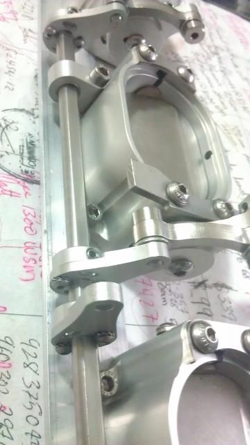
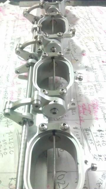
Some pics of the linkages and actuators for the 7.0 litre stroker
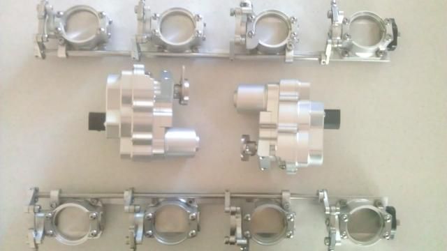
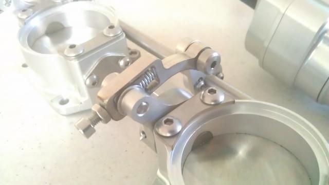
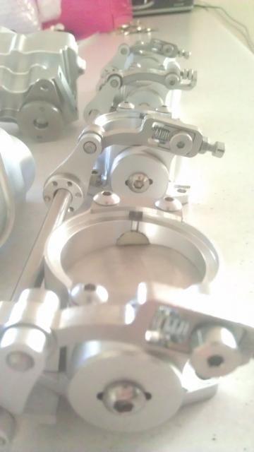
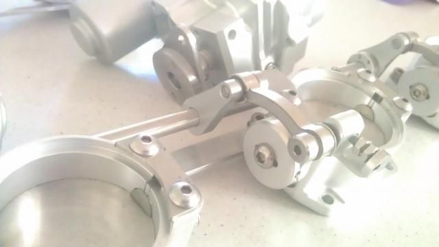
As usual the pics could be better but the parts are beautifully made, I am using photobucket but it seems very low quality, is there a better free site for hi def?
As usual the pics could be better but the parts are beautifully made, I am using photobucket but it seems very low quality, is there a better free site for hi def?
03-08-2014, 07:03 AM
#34
Race Car
03-19-2014, 09:15 AM
#35
Addict
Rennlist Member
Rennlist Member
Thread Starter
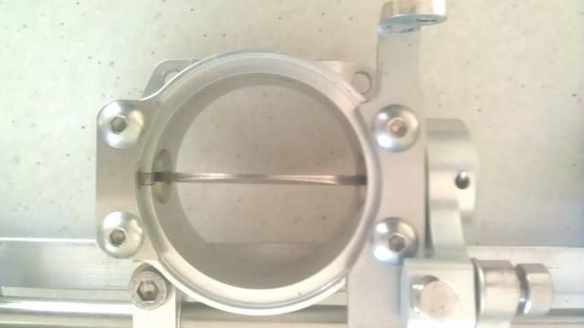
O.K now we have the 55 mm throttle bodies,
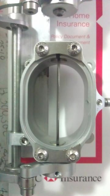
it will be a pretty tight fit with the trumpets where they crossover. I haven't decided on tapered or non tapered trumpets, maybe the packaging will dictate that anyway. The trumpets will have motor bike 10 spray hole injectors fitted into the trumpets but angled as closely as I can at the back of the valves. Those injectors are good for 400 hp alone and will only kick at high revs and will not operate at all at low rpms. This will be left to the lower injectors which will also be sequential. Most likely 4 spray hole unless there is something better that isn't too expensive. However I will run the fuel pressure the same as the S4 which is higher than I have with the S. In F1 they found the more they turned up the pressure, the more power they made. Prior to the current dfi engines the fuel pressure was capped at a massive 200 bar.

You will notice the air bleeds to internally balance the throttles. These throttles will also run the electronic throttle actuators. I was giving some thought to running a EGR system for off throttle coasting, that is less engine braking and are said to provide slightly better economy and better emissions.
However I was wondering about the programming which I know little about. However the throttle blade angle can be varied when the accelerator is in the 0% position. So you can do a fuel cut depending on the rpm and then provide a certain amount of throttle angle which then may alter the amount of engine braking. You may not want to have a lot of engine braking at very high speeds as this may unsettle the car.
On the pistons, no luck with Capricorn, they wont do one set. So it might be back to CP. I did obtain my wrist pins, they are Italian pins made by Veca, after much research I decided I could run a pin as short as 1.80" with my 0.787" Pankl rods, Veca make a lot of smaller items for various F1 engines so they are familiar with specific loadings associated in high power and high RPM engines. The pins weigh 90 grams and are 0.210" thick. This should make for a very stiff assembly. The total bob weight is designed to come out under 1500 grams.
Many of you would know that I first raised the issue of mass forces cracking the blocks in stroker motors. It is my belief that heavy parts swinging a lot further from the centreline of the factory crankshaft adds loadings that the block cannot cope with. This is one the reasons for my reduced stroke cranks and certainly the reason I have reduced the rod bearing diameter and thus associated mass forces. I am going to go one further with this engine and reduce the mains and groove my own bearings.
I will hopefully shortly find out how much that is all going to cost. I am also giving very serious consideration to making the bedplate and sump in a billet. That is all in one piece. This should stiffen the block and greatly reduce any chance of cracking the block given I will use replaceable 108 mm alloy wet liners. It will also save some machining operations and will it will be more expensive it is how most race teams do it such as the team running the Porsche Cayenne engine.
The exhaust components are also on order and will soon be on their way, I have decided to only have one step in the primary, this is really to avoid too much complication and cost. The cost of these parts is just hyper, every little piece of tube is around $150, each step ring is $100 so it adds up too quickly to be worthwhile.
The system will now be 2 1/8" off the head, and this will be in slightly thicker pipe, at 0.9 mm (as it has to support the front of the system) and then stepping to 2 1/4" before going into the first set of collectors in the tri-y system. These collectors have 2 1/2" outlets and these then go into the secondary collectors which have 3 1/2" outlets. This is the size of the main system and the end of the inconel. It will then change to 321 stainless 3 1/2" pipe with custom mufflers. I am going to have a hard time to quieten down this beast and I will use the area where the 928S had its first muffler to build basically a bigger but light weight version of this muffler with internal H pipe. I am not going to use gutted GT mufflers as these will not be sufficient, I will construct something like the factory mufflers in size and cross my fingers that will be enough.
it will be a pretty tight fit with the trumpets where they crossover. I haven't decided on tapered or non tapered trumpets, maybe the packaging will dictate that anyway. The trumpets will have motor bike 10 spray hole injectors fitted into the trumpets but angled as closely as I can at the back of the valves. Those injectors are good for 400 hp alone and will only kick at high revs and will not operate at all at low rpms. This will be left to the lower injectors which will also be sequential. Most likely 4 spray hole unless there is something better that isn't too expensive. However I will run the fuel pressure the same as the S4 which is higher than I have with the S. In F1 they found the more they turned up the pressure, the more power they made. Prior to the current dfi engines the fuel pressure was capped at a massive 200 bar.
You will notice the air bleeds to internally balance the throttles. These throttles will also run the electronic throttle actuators. I was giving some thought to running a EGR system for off throttle coasting, that is less engine braking and are said to provide slightly better economy and better emissions.
However I was wondering about the programming which I know little about. However the throttle blade angle can be varied when the accelerator is in the 0% position. So you can do a fuel cut depending on the rpm and then provide a certain amount of throttle angle which then may alter the amount of engine braking. You may not want to have a lot of engine braking at very high speeds as this may unsettle the car.
On the pistons, no luck with Capricorn, they wont do one set. So it might be back to CP. I did obtain my wrist pins, they are Italian pins made by Veca, after much research I decided I could run a pin as short as 1.80" with my 0.787" Pankl rods, Veca make a lot of smaller items for various F1 engines so they are familiar with specific loadings associated in high power and high RPM engines. The pins weigh 90 grams and are 0.210" thick. This should make for a very stiff assembly. The total bob weight is designed to come out under 1500 grams.
Many of you would know that I first raised the issue of mass forces cracking the blocks in stroker motors. It is my belief that heavy parts swinging a lot further from the centreline of the factory crankshaft adds loadings that the block cannot cope with. This is one the reasons for my reduced stroke cranks and certainly the reason I have reduced the rod bearing diameter and thus associated mass forces. I am going to go one further with this engine and reduce the mains and groove my own bearings.
I will hopefully shortly find out how much that is all going to cost.
I am also giving very serious consideration to making the bedplate and sump in a billet. That is all in one piece. This should stiffen the block and greatly reduce any chance of cracking the block given I will use replaceable 108 mm alloy wet liners. It will also save some machining operations and will it will be more expensive it is how most race teams do it such as the team running the Porsche Cayenne engine.The exhaust components are also on order and will soon be on their way, I have decided to only have one step in the primary, this is really to avoid too much complication and cost. The cost of these parts is just hyper, every little piece of tube is around $150, each step ring is $100 so it adds up too quickly to be worthwhile.
The system will now be 2 1/8" off the head, and this will be in slightly thicker pipe, at 0.9 mm (as it has to support the front of the system) and then stepping to 2 1/4" before going into the first set of collectors in the tri-y system. These collectors have 2 1/2" outlets and these then go into the secondary collectors which have 3 1/2" outlets. This is the size of the main system and the end of the inconel. It will then change to 321 stainless 3 1/2" pipe with custom mufflers. I am going to have a hard time to quieten down this beast and I will use the area where the 928S had its first muffler to build basically a bigger but light weight version of this muffler with internal H pipe. I am not going to use gutted GT mufflers as these will not be sufficient, I will construct something like the factory mufflers in size and cross my fingers that will be enough.
 03-19-2014, 11:50 AM
#37
 03-19-2014, 10:47 PM
#38
Addict
Rennlist Member
Rennlist Member
Thread Starter
I still need to get the exhaust flanges cut on the CNC, I am not going just water jet cut flanges for this system. Regarding the design, I have certainly been helped by the first inconel system which is not yet totally complete as yet due to time constraints but it is looking good.
03-19-2014, 11:05 PM
#39
I didn't know they were pricey. What do you mean hire? You mean rent?
I am looking at just changing some cheap MSDS headers a bit and adding a step. I started to look for "step rings" from your post and found that link I posted.
I am looking at just changing some cheap MSDS headers a bit and adding a step. I started to look for "step rings" from your post and found that link I posted.
03-20-2014, 09:40 PM
#42
03-20-2014, 10:08 PM
#44
Addict
Rennlist Member
Rennlist Member
Thread Starter
As I said it is expensive and that is why you would hire instead of buying, their system only goes to 2" and my pipes are bigger and while it would be a help, you have to draw the line somewhere. Next step for my project is the custom flanges.
03-21-2014, 03:44 AM
#45
Addict
Rennlist Member
Rennlist Member
Thread Starter
To get this done, I don't work, I did employ a full time house keeper and nanny for 7 months last year just to be able to get these tasks done and because I am learning on the job things take a lot of time. I am thinking about employing a panel beater part time to help with the body. I have come too far to look back now.
I am also thinking about wrapping the body. More on that later. When I go to Queensland I am going to try to get a price on a carbon roof panel. These are the guys that make the V8 Supercar parts, don't expect Chinese prices but the quality is different too. My engineer tells me cages are not legal here so I may need to try and hide some of the strengthening. He says it is about triangulating the stresses more than reinforcing.
I will start a different thread for the gearbox because I want as many people to see it as possible. The update there is that I had the engineers that made the V8 Supercar box come over and they were quick with some solutions and were keen to do this project.
The problem is that the 7 speed box with the correct ratios is not available till early next year, there is a 6 speed box with the same ratios but obviously missing 7th gear or the economy gear, both are very strong, the six speed is rated at 650 ft pounds and the 7 speed at 635 ft pounds of torque. The engineers suggested that I make the diff a stand alone piece and we may make the bearing carrier longer to help better support the driveshaft.
As I have mentioned before, the first ring and pinion is $10K AUD or $9K USD and the mainshaft is about $2K AUD. This drops down dramatically with the subsequent pieces, about $3K for the ring and pinion and $1500 for the mainshaft out of the gearbox. The adaptor plate will be about $2K also for the first one.
All this work is to have the use of the porsche diff and the fitment remains factory. Of course the new C7 Vette also uses a active diff but it looks really big and really I want a different rear end ratio although you do lose strength when you make the ratio higher. Anyway the prices for these conversion parts should be around $7K on an ongoing basis using 5 sets to amortise the investment if that is possible but the project doesn't depend on that. If someone was interested let me know and I will also share for a reasonable cost the software for the custom PSD programming.
I am also looking to add the Variocam feature, I need to make this part from billet most likely an alloy and I have worked out how to make this work. That is push the chain in the correct direction which is the opposite direction to the other tensioner. This feature is not for power, it is not for some fancy feature, it is not for switching backwards and forwards during driving. The Porsche Cup cars do not have variocam nor do most race cars, however they never go on the road.
The ECU which has 6 cabin switchable maps will have a street and race setting. I anticipate the street setting will always run the engine in wide LSA mode. This will take the tiger out of the cam and hopefully make the car drivable at low speeds. We are talking about a big cam here, the engineer I spoke to said that my radius or what they call convex tappets will add to drivability. The throttle bodies will also add to drivability but when you seek peak power at 8,500 rpm the cam is pretty big.
However in race mode the cam will basically only operate in tight LSA mode, the tensioner needs oil pressure to change the cam position so I would think that once the engine is over about 2,000 rpm it could be switched over. Tell me what you think!