
My 928 Projects Master Thread

 01-18-2014, 06:24 PM
#17
Addict
Rennlist Member
Rennlist Member
Thread Starter
Certainly a challenge although the technology is proven but just not in a 928 engine, I can't afford to blow a couple engines up to sort out issues so that is where the real challenge of the engineering exists. So I have the best people I can find helping me, an example is the fellow helping with the intake, he worked for 20 years in V8 Supercar and did 3 years solid research making development intakes and throttle bodies.
Hopefully this will pay dividends and avoid dramas as I only really have the funds and time to do this once. I do funny enough feel I am wasting my time but I almost died a few months ago from septic shock and as I laid on the table, many things went through my head, the kids and and no will! and all these parts were going to go in the bin. So thought if I survive I better get things in order. The 2V project was simplified now using 928 S2 heads and the 4V project..... well I thought, go hard or go home!
I will see what time I have today but I may post the flow numbers I have to achieve to get to my target power numbers. The intake is important but the key appears to be the required exhaust flow, from memory and I will clarify but I think I need close to 300 cfm on the exhaust. We will be sectioning a head soon and I may trial port an exhaust port, we will also use that head to determine the exhaust valve size. I am starting off with 36 mm exhaust valves and will experiment with up to 38 mm to see what happens with the flow. The outlet size of the port will be 49 mm. I would be interested to hear from anybody who has played with these ports as I haven't touched them before.
01-19-2014, 07:13 AM
#19
Rennlist Member
Join Date: Feb 2011
Location: Mostly in my workshop located in Sweden.
Posts: 2,230
Received 463 Likes
on
248 Posts
Just in order to clarify things, Greg is building two stroker engines. One 16V having much torque and not very high revving for the automatic car, think it is his wifes car. I am not sure but it will be about 6,5 litre. The other engine 7 litre 32V for the manual car will be built for maximum output and I am really excited to see the result. Both engines will have ITB�s and custom built headers by Greg himself.
�ke
�ke
�ke
�ke
01-19-2014, 10:22 AM
#21
Addict
Rennlist Member
Rennlist Member
Thread Starter
Just in order to clarify things, Greg is building two stroker engines. One 16V having much torque and not very high revving for the automatic car, think it is his wifes car. I am not sure but it will be about 6,5 litre. The other engine 7 litre 32V for the manual car will be built for maximum output and I am really excited to see the result. Both engines will have ITB�s and custom built headers by Greg himself.
�ke
�ke
�ke
�ke
01-19-2014, 11:55 AM
#22
Rennlist Member
Join Date: Feb 2011
Location: Mostly in my workshop located in Sweden.
Posts: 2,230
Received 463 Likes
on
248 Posts
�ke
 01-22-2014, 07:30 PM
#25
Rennlist Member
I really dont like those ratos, except for 1st which makes sense for 1st gear and the carbon clutch.
you dont have a 4.6 (3rd) or a 3.2 (4th) ratio , like the 928S4, which gives redline in a very usable range of 118mph and 155mph.
If you could change them to get the ratios closer together after 80mph, it would help it gain more effective hp when you need it most on the track.
you dont have a 4.6 (3rd) or a 3.2 (4th) ratio , like the 928S4, which gives redline in a very usable range of 118mph and 155mph.
If you could change them to get the ratios closer together after 80mph, it would help it gain more effective hp when you need it most on the track.
01-23-2014, 06:59 AM
#26
Addict
Rennlist Member
Rennlist Member
Thread Starter
I really dont like those ratos, except for 1st which makes sense for 1st gear and the carbon clutch.
you dont have a 4.6 (3rd) or a 3.2 (4th) ratio , like the 928S4, which gives redline in a very usable range of 118mph and 155mph.
If you could change them to get the ratios closer together after 80mph, it would help it gain more effective hp when you need it most on the track.
you dont have a 4.6 (3rd) or a 3.2 (4th) ratio , like the 928S4, which gives redline in a very usable range of 118mph and 155mph.
If you could change them to get the ratios closer together after 80mph, it would help it gain more effective hp when you need it most on the track.
So just for the record here are the ratios that are available in the C7 Corvette the option of the Sports pack (Z51) puts a oil pump into the transmission which is pretty important. It makes the 6th gear relevant for high speed runs, 7th gear is an economy gear which I don't mind.
................................... C7......Z51
First gear................... 2.66 .. 2.97
Second gear............. .1.78 .. 2.07
Third gear............... ..1.30 .. 1.43
Fourth gear............... 1.00 .. 1.00
Fifth gear.................. 0.74 .. 0.71
Sixth gear................. 0.50 .. 0.57
Seventh gear..............0.42 .. 0.48
Reverse..................... 2.90 .. 2.90
So you can see the Z51 ratios are wider, I want to keep then close as I think this may assist shift quality as we are still talking a synchromesh transmission. The issue you may have not considered was the power curve and rpm capability of the engine. Peak power will hopefully be in the 8,000 to 8,500 rpm range with a redline of 9,000.
I was told to ring Liberty gears to see if they can do something regarding the ratios. I will have to do that next week. I am also considering different manufacturers for the ring and pinion as I think $10K AUD is very expensive.
The Corvette box is an attractive option if we can get it right regarding the ratios, the strength and operation I am told are superb, we can get a carbon driveshaft cheaply, we can rev match this gearbox through the ECU. It is the right size and the shifter linkage is similar.
I spoke to the Tilton technical adviser and he agreed with a lower first gear and gave advice on how to get the smoothest engagement. It comes down to a recommended 44 mm throwout bearing with the suggested 19 mm master cylinder. I don't know what the 928 master cylinder diameter is but I suspect I will find out soon enough.
I also spoke to Moldex today re the crankshaft and they were ready to listen and sounded quite accommodating, I will pursue this avenue further.
01-25-2014, 06:08 PM
#27
Addict
Rennlist Member
Rennlist Member
Thread Starter
The below except appeared in an article from the following URL
http://www.aera.org/ep/downloads/ep8/EPQ409_26-27.pdf
The information came from Bill McNight
Recognize the obvious
Upper rod bearings and lower main shells get most of the load so your inspection always focuses on them first! A simple thought, not always possible especially on older performance engines, is: no groove on the lower main shell. All that groove does is effectively reduce the load bearing capability of an already heavily loaded part. Most of our NASCAR customers make their own upper main shells from un-grooved lower shells. Without giving away any secrets, they look carefully at both the width of the groove as well as its overall length.Always remember, regardless of the type of performance engines you build or the type of service the engine sees, as you increase the demand for making power, you will exceed the capabilities of the standard bearing and eventually, even the capabilities of the standard racing bearing.
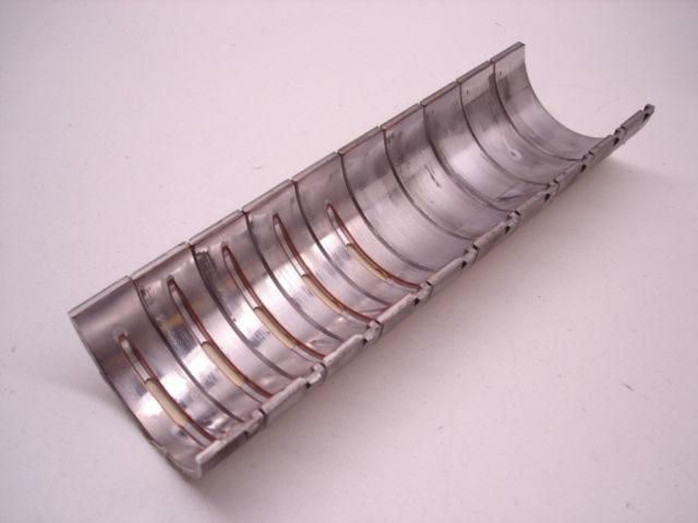
Mahle Clevite also have documented in their advice to engine builders, basically the grooving we have which is at best 220 degrees. Having mains grooved with 220 degrees of grooving is far from optimal. The Mahle info is below;
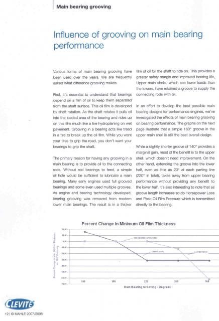
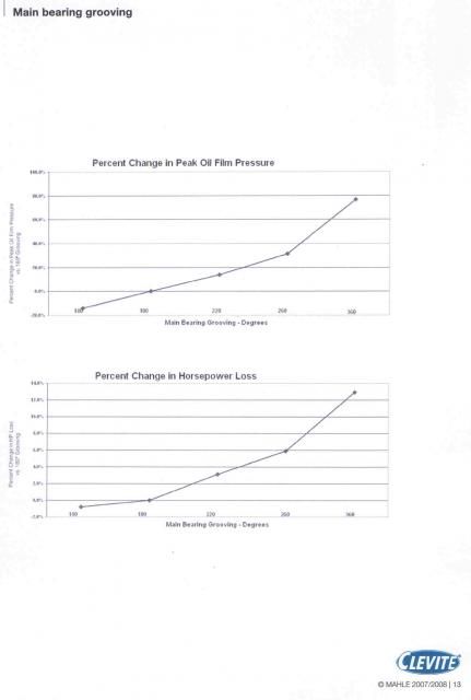
The Mahle document was in PDF format and I scanned it but I am sorry about its clarity once I uploaded it. You can search that document and it is worth the read. You can see what they are doing in Nascar regarding main bearings, those bearings are from the current RO7 Chev engine which uses 2" main bearings. So if you don't get that right with such small mains you will get trouble very quickly.
If I get time I will upload the pics of the main bearing that have come out of a factory assembled 928 engine, you will see more wear on them than on these Nascar bearings. Clearly the Nascar engine gets a lot of maintenance but the wear patterns are more relevant and you can see the shaft climbing the walls of the 928 main bearings, I put that down to the loss of support due to the oil film being sheered from excessive pressure being developed because the grooving has taken away the ability of the bearing and oil to support the shaft.
The text below is from a post I wrote a few years ago now, it is relevant to what we are discussing here, it goes into more of the technicalities of the subject.
Bearing friction is measured and valued by the equation of "Bearing Operating Condition" (BOC) BOC = Viscosity x RPM x K/Load The K is the factor that converts RPM and diameter into journal speed. (Which is why there is a gain from smaller journals) To me this formula is a bit counter intuitive, the reason I say this is is, with a greater load the friction is lowered to a point but it is always lower than boundary.
So with the use of smaller mains the load is proportionally increased, this helps the bottom number in the division by making it a larger number, the top number is made smaller by the fact as mentioned earlier the K factor. So it is win win in regards to friction. While friction is reduced due to lower viscosity oils, I wouldn't go there, some Nascar Teams still use 20W-50 and that is where I will stay unless there is a need for a 60 weight oil which some race cars use.
While doing my research for this topic I dug up this info from the SAE.
http://www.sae.org/events/pfs/presen...2005spikes.pdf
On page 46 there is the conclusion to a wear study that was conducted and the basis of the study was ZDDP and its effects. Now this might explain something that is important to all of us.
That is why some oils have caused high wear or maybe put another way allowed high wear. So oils that are not high in ZDDP may be doing more damage than oils with none! This may explain problems seen with Mobil 1. Various grades of Mobil 1 have different formulations.Another Rennlister JET951 may like to expand on this is his area given that he rebuilds these engines. Also if I understood it correctly there is increased friction when there is mixed lubrication when ZDDP is used. Maybe this is a by product of the mechanism of action? That is the protection offered slightly increases the friction.
There is some other issues that may be of interest, I will try to explain the terminology as best I can so that it makes sense, I have condensed the article so that if you have a question please ask it.
Back to the types of lubrication, boundary lube. is when there is a few molecules of oil between the sliding surfaces and the peaks of each surface touch each other. This is the highest friction and occurs on cold start up, a hydrodynamic wedge forms as the journal rotates and the oil is trapped. There is little pressures on the edges as the pressure escapes and peak pressure is in the centre of the bearing.
This is why grooved bearings cannot carry anywhere near the same load, (If a pic is desired i can draw it but the article and photos are copyright protected) if the bearing was wide enough pressure would peak and be level in the centre. I think that Porsche when they made this change, were just worried about the damage to the rod bearings that was happening in the marketplace and tried this as a fix not because it was better.
The film thickness may only be around 0.0001" but the pressure may be as high as 6,000 psi. Hydrodynamic pressure has nothing to do with engine oil pressure, the only relationship will be is there enough oil to cool the bearings and keep the hydrodynamic wedge going. Also the opening out of the oil galleries on the rod journals is bad for the same reasons. The opening needs to be kept small with only a small radius to relieve any stress.
The third mode is mixed, that is part hydrodynamic and part boundary. It is the transition between the two types of lubrication. There is a another type of lube that is not applicable to fluid film bearings and that is squeeze film. It is the type of lubrication that is seen in wrist or piston pins.
A bit of terminology, bearing eccentricity, I normally associated this with rod bearings, however it is also associated with the lubrication modes. Bearing eccentricity is the journal displacement from the centreline of the housing. That is off to one side, the journal does start to climb the wall of the journal as the journal or shaft starts turning.
An example may be, the mains or rods may have a 0.003" clearance. Or a radial clearance of 0.0015" and is operating with a oil film thickness of 0.0001". The sum would be (0.0015 - 0.0001)/0.0015= 0.9333" The actual shaft/journal diameter was not supplied in the article so that was not that helpful.
Looking at the Stribeck graph it shows that the friction starts off very high and as the journal starts to turn the hydrodynamic pressure starts to build and take over from the boundary lube. If rpm stays fixed and either viscosity decreases or unit load increases it will eventually reach its low point of friction of a BOC of 35. That value put into perspective is half the friction of a deep groove ball bearing.
If the loading continues to go up and or the viscosity decreases the BOC will move into the mixed lube mode where there is minor metal to metal contact. If this happens you have too low a viscosity oil or your bearings are too narrow.
I believe one of the reasons the crank that I have that looks like a mirror is polished in that way, is that they are are trying to keep those peaks and valleys to an absolute minimum to reduce this mixed lubrication.
From the low point of BOC 35 it only goes one way, if higher revs or higher viscosity or lower unit load, the friction rises exponentially or to approx ten times the low point. This is why much attention is paid to getting this right. Designers need to maintain the 35 to 50 BOC range.
Now when we reduce the mains and rod journals we also reduce the overlap, Current Nascar engines with approx. 870 HP have journal overlap of 7 mm and if I was to choose a main bearing diameter of 2 1/2" with a 3.55" stroke we would have a bit over 10 mm of overlap. This allowing for appropriate design and material should be adequate in terms of strength while not adding too much weight. The issue becomes one of cost, this engine project is expensive, more expensive than it would if more than one engine was produced as much cost is in the CAD and development. Not that this would ever be cheap.
http://www.aera.org/ep/downloads/ep8/EPQ409_26-27.pdf
The information came from Bill McNight
Recognize the obvious
Upper rod bearings and lower main shells get most of the load so your inspection always focuses on them first! A simple thought, not always possible especially on older performance engines, is: no groove on the lower main shell. All that groove does is effectively reduce the load bearing capability of an already heavily loaded part. Most of our NASCAR customers make their own upper main shells from un-grooved lower shells. Without giving away any secrets, they look carefully at both the width of the groove as well as its overall length.Always remember, regardless of the type of performance engines you build or the type of service the engine sees, as you increase the demand for making power, you will exceed the capabilities of the standard bearing and eventually, even the capabilities of the standard racing bearing.
Mahle Clevite also have documented in their advice to engine builders, basically the grooving we have which is at best 220 degrees. Having mains grooved with 220 degrees of grooving is far from optimal. The Mahle info is below;
The Mahle document was in PDF format and I scanned it but I am sorry about its clarity once I uploaded it. You can search that document and it is worth the read. You can see what they are doing in Nascar regarding main bearings, those bearings are from the current RO7 Chev engine which uses 2" main bearings. So if you don't get that right with such small mains you will get trouble very quickly.
If I get time I will upload the pics of the main bearing that have come out of a factory assembled 928 engine, you will see more wear on them than on these Nascar bearings. Clearly the Nascar engine gets a lot of maintenance but the wear patterns are more relevant and you can see the shaft climbing the walls of the 928 main bearings, I put that down to the loss of support due to the oil film being sheered from excessive pressure being developed because the grooving has taken away the ability of the bearing and oil to support the shaft.
The text below is from a post I wrote a few years ago now, it is relevant to what we are discussing here, it goes into more of the technicalities of the subject.
Bearing friction is measured and valued by the equation of "Bearing Operating Condition" (BOC) BOC = Viscosity x RPM x K/Load The K is the factor that converts RPM and diameter into journal speed. (Which is why there is a gain from smaller journals) To me this formula is a bit counter intuitive, the reason I say this is is, with a greater load the friction is lowered to a point but it is always lower than boundary.
So with the use of smaller mains the load is proportionally increased, this helps the bottom number in the division by making it a larger number, the top number is made smaller by the fact as mentioned earlier the K factor. So it is win win in regards to friction. While friction is reduced due to lower viscosity oils, I wouldn't go there, some Nascar Teams still use 20W-50 and that is where I will stay unless there is a need for a 60 weight oil which some race cars use.
While doing my research for this topic I dug up this info from the SAE.
http://www.sae.org/events/pfs/presen...2005spikes.pdf
On page 46 there is the conclusion to a wear study that was conducted and the basis of the study was ZDDP and its effects. Now this might explain something that is important to all of us.
That is why some oils have caused high wear or maybe put another way allowed high wear. So oils that are not high in ZDDP may be doing more damage than oils with none! This may explain problems seen with Mobil 1. Various grades of Mobil 1 have different formulations.Another Rennlister JET951 may like to expand on this is his area given that he rebuilds these engines. Also if I understood it correctly there is increased friction when there is mixed lubrication when ZDDP is used. Maybe this is a by product of the mechanism of action? That is the protection offered slightly increases the friction.
There is some other issues that may be of interest, I will try to explain the terminology as best I can so that it makes sense, I have condensed the article so that if you have a question please ask it.
Back to the types of lubrication, boundary lube. is when there is a few molecules of oil between the sliding surfaces and the peaks of each surface touch each other. This is the highest friction and occurs on cold start up, a hydrodynamic wedge forms as the journal rotates and the oil is trapped. There is little pressures on the edges as the pressure escapes and peak pressure is in the centre of the bearing.
This is why grooved bearings cannot carry anywhere near the same load, (If a pic is desired i can draw it but the article and photos are copyright protected) if the bearing was wide enough pressure would peak and be level in the centre. I think that Porsche when they made this change, were just worried about the damage to the rod bearings that was happening in the marketplace and tried this as a fix not because it was better.
The film thickness may only be around 0.0001" but the pressure may be as high as 6,000 psi. Hydrodynamic pressure has nothing to do with engine oil pressure, the only relationship will be is there enough oil to cool the bearings and keep the hydrodynamic wedge going. Also the opening out of the oil galleries on the rod journals is bad for the same reasons. The opening needs to be kept small with only a small radius to relieve any stress.
The third mode is mixed, that is part hydrodynamic and part boundary. It is the transition between the two types of lubrication. There is a another type of lube that is not applicable to fluid film bearings and that is squeeze film. It is the type of lubrication that is seen in wrist or piston pins.
A bit of terminology, bearing eccentricity, I normally associated this with rod bearings, however it is also associated with the lubrication modes. Bearing eccentricity is the journal displacement from the centreline of the housing. That is off to one side, the journal does start to climb the wall of the journal as the journal or shaft starts turning.
An example may be, the mains or rods may have a 0.003" clearance. Or a radial clearance of 0.0015" and is operating with a oil film thickness of 0.0001". The sum would be (0.0015 - 0.0001)/0.0015= 0.9333" The actual shaft/journal diameter was not supplied in the article so that was not that helpful.
Looking at the Stribeck graph it shows that the friction starts off very high and as the journal starts to turn the hydrodynamic pressure starts to build and take over from the boundary lube. If rpm stays fixed and either viscosity decreases or unit load increases it will eventually reach its low point of friction of a BOC of 35. That value put into perspective is half the friction of a deep groove ball bearing.
If the loading continues to go up and or the viscosity decreases the BOC will move into the mixed lube mode where there is minor metal to metal contact. If this happens you have too low a viscosity oil or your bearings are too narrow.
I believe one of the reasons the crank that I have that looks like a mirror is polished in that way, is that they are are trying to keep those peaks and valleys to an absolute minimum to reduce this mixed lubrication.
From the low point of BOC 35 it only goes one way, if higher revs or higher viscosity or lower unit load, the friction rises exponentially or to approx ten times the low point. This is why much attention is paid to getting this right. Designers need to maintain the 35 to 50 BOC range.
Now when we reduce the mains and rod journals we also reduce the overlap, Current Nascar engines with approx. 870 HP have journal overlap of 7 mm and if I was to choose a main bearing diameter of 2 1/2" with a 3.55" stroke we would have a bit over 10 mm of overlap. This allowing for appropriate design and material should be adequate in terms of strength while not adding too much weight. The issue becomes one of cost, this engine project is expensive, more expensive than it would if more than one engine was produced as much cost is in the CAD and development. Not that this would ever be cheap.
02-04-2014, 07:18 PM
#28
Addict
Rennlist Member
Rennlist Member
Thread Starter
So..... with regard to the 7 speed conversion, I have bought a late model auto transaxle to send the differential to the gear maker. I will take this down to Melbourne in March when we go to the Grand Prix however I will be sending more details to the gear maker for rough estimates and to see whether he thinks such a short ratio is indeed possible in the 928 diff housing.
With regard to costings, they are a bit eye watering, just rough prices mind you and my best guesstimates.
Transmission new TR6070 superfinished cyroed carbon syncro rings etc. $6,000 to $7,000 depending on ratios.
Used Torque Tube and bell Housing with shifter $1,000
Shifter 7speed **** and boot $500
Carbon drive shaft $2,000
Custom 928 Flywheel $1,500-$2K
Custom throw out bearing $500
Adaption of Corvette tube to 928 Bell housing $500 to $1,000
Adaption of TR6070 to 928 Differential $2500
Custom mainshaft/output shaft 300M $2500
Custom Ring & Pinion superfinished $10,000
For me shipping and customs $2000
I already have the Carbon Clutch $5,000
Total $36,000 when you use the high estimates and add my clutch. Admittedly I will sell my GT driveline and what point is there in blowing that up, it also wont handle the high RPM changes as it doesn't have triple cone syncros like the TR6070.
If anybody wanted to also do this some of the costs would come down due to duplication I suppose $5K cheaper and also the shipping and customs could be deducted if you were in the States. I may also have some of these costs wrong, we will find out more as it progresses.
If I was to use the Corvette differential, the crown wheel and mainshaft could be deducted but you would have to add in a new Corvette differential, I am not too sure how well that will fit due to its increased size as it is considerably reinforced. I suppose it would cost around $4K itself and then you would have to decide on a LSD or the active differential. I think the 928 is easier to do if you wanted to go down the active differential route.
02-07-2014, 08:12 PM
#29
Addict
Rennlist Member
Rennlist Member
Thread Starter
O.K spoke to the manufacturer of the custom ring and pinion, he says the problem may well be the pinion gets too small. The issue is as the pinion gets smaller the shaft splines where the nut is situated gets closer to the start of the pinion teeth. As such there is not enough strength. There is 10 mm or 3/8" from the splines to the pinion teeth. The crown wheel may be able to be made slightly bigger and maybe I have to consider a ratio smaller than 4.0:1 maybe 3.77 or something in that range. You could make the shaft thinner but again you are reducing strength when you actually need more or at least a better material for that shaft. We wont know more until mid March when we go to Melbourne with the differential and we are going to meet the engineer at the Aust GP with the 928 differential.
02-08-2014, 12:08 AM
#30
Addict
Rennlist Member
Rennlist Member
Thread Starter
The ratios have just been released for the Z06, they are very close ratios,
They are;
1st:. 2.29
2nd: 1.61
3rd: 1.21
4th: 1.00
5th: 0.82
6th: 0.68
7th. 0.45
Given these are pretty terrific ratios I will be very disapointed if we can't achieve a 4.0:0 to 1 diff ratio. First gear will be a bit taller than stock in the GT but I always found myself stuck between choosing 1st or second to take off in
I am familiar with how they set the depth of the pinion in the auto box, that is pretty easy to understand, but I have never looked for the manual, perhaps we could get the driveshaft made with the pinion gear integral and this will eliminate the problem where the pinion gets too small and causes the issue I outlined in the previous post