When you click on links to various merchants on this site and make a purchase, this can result in this site earning a commission. Affiliate programs and affiliations include, but are not limited to, the eBay Partner Network.
Anyway- some of the adjustable fan controllers can be had with a threaded sending unit.
How about an adapter to screw into the OEM sending unit at the bottom of the radiator, and that adapts to NPT thread to accept the most common aftermarket sending unit configuration? Would a sufficiently resilient plastic of some sort be cost prohibitive?
I also had a air intake start to crack, we discussed three of four frenzys ago. Maybe I can catch up with you at the next one.
I bought a Hayden digital fan controller from OReilly's a few years back to control my dual Mercury Contour fan mod I installed in my 79. Has a temp bulb that screws into the old AUX fan controller hole in the radiator so no pushing a probe into my radiator fins. I mounted it in the spot where the intensive washer reservoir use to be. For less that $100 it has worked flawlessly. Controls fans independent and together with variable speed as well as having soft start power draw. I did a AUX electric fan delete and even with AC on in a Texas summer it drives the Contour fans perfectly.
Jim,
Your post implies that Hayden do a temp sender unit that fits the std M22x1.5 thread in our radiator tanks, correct? I see they mention a 3/8 NPT sender, but not one in our thread? Normally our fittings are on/off switches, they dont send a temp signal AFAIK.
Re the 'low profile shroud', I have a 2x11" SPAL assembly mounted on a home made frame, and its so shallow that I can do a belt job without removing the fan assembly.
jp 83 Euro S AT 57k
I ordered a M22 to 1/8 adapter online so I could pull the OEM AUX fan on/off temp switch out of the radiator and insert the M22 adapter and 3/8 temp probe from the Hayden into the radiator opening.
I bought a Hayden digital fan controller from OReilly's a few years back to control my dual Mercury Contour fan mod I installed in my 79. Has a temp bulb that screws into the old AUX fan controller hole in the radiator so no pushing a probe into my radiator fins. I mounted it in the spot where the intensive washer reservoir use to be. For less that $100 it has worked flawlessly. Controls fans independent and together with variable speed as well as having soft start power draw. I did a AUX electric fan delete and even with AC on in a Texas summer it drives the Contour fans perfectly.
Jim, I have been thinking about doing this for a looong time, never got around to it. Finally, I am going to tackle it during this winter, along with a few other delayed/neglected jobs.
I am planning to do exactly what you've done on your '79 You would make the project a lot easier if I could piggy-back on your experience and details. Would you be so kind and share with me, in your spare time, some of the key points, pics of wiring details, etc., if you have taken any pics, notes, along the way.
You mentioned the radiator temp. probe adapter. Where exactly did you buy it from ? "on line" is a big place, I could spend days searching for the source.
Also, Hayden's part spec.s for the 3655 controller say "one fan per controller" Did you use two controllers or just one ? If just one, can it handle both fans and how do you make them run independently or together ?
You can respond here or PM me with details you can share. Thanks in advance,
Some inconsistencies on Hayden. Web site says optional 355 sensor is 3/8 NPT, but Summit says its 1/8 NPT? Cant find the part where it says 'one fan per controller', but the Hayden instructions always refer to 'fanS'? With only one pair of connections for fan output, how can the controller run fans together or separately?
jp 83 Euro S AT 57k
Let me take some pic's of the fan controller install/ wiring and I will post some stuff here in the next day or so. I have both fans wired to run together. You really can't/ don't want to run them separately as following the path of least resistance law a single fan will pull engine bay air in from the none running side before it would pull obstructed air through the radiator. I have it wired to start both fans on high when AC is on. The instructions were pretty easy to follow and the soft start has never blown the inline 30AMP fuse for me.
As for the temp probe it is an accessory from Hayden. Its a 2 wire 1/8th NPT threaded temp probe.
I have been poking around for a week or two, looking at different controllers, fan shroud assy.s,, probe adapters, etc.
I have more or less decided on going with the Hayden 3655 controller and run the fans simultaneously. I figure it should work fine since the Contour aftermarket shroud & fan assy. from Dorman draws only 12 AMPs, 5.8 per side, according to their tech support guy. BTW, they were the only outfit that knew the AMP draw of this fan assy., nobody else had a clue. I believe the original Contour fans drew a few more amps but would be still within the 24 AMP max. for this controller. I could no longer find any used/original Contour fan assy.s around here so I decided to go with the aftermarket option. They are not that expensive, they are new and exact replicas of the original.
Did you utilize the existing pwr. feed wires from the A/C pusher fan on our cars or did you run brand new wires to power the Hayden controller ?
I ran a 12V 12 G supply wire from the starter post up to the the controller to ensure the best voltage supply. The deleted AUX cooling fan supply plug is not used as I feared it could not support the full 30 AMP protection of the Hayden in line fuse.
I was fortunate to find the Contour fans with wiring pig tails at a junk yard and then used weather tech connectors to connect the OEM wiring to the wires running to the Hayden controller.
I tapped into the windshield wiper wiring for ignition signal as that wire was accessible under the wiper shroud in the engine bay running forward along the passenger side wire bundle to the front where I removed the intensive wash reservoir and placed the Hayden (out of the heat of the engine bay).
Let me take some pic's of the fan controller install/ wiring and I will post some stuff here in the next day or so. I have both fans wired to run together. You really can't/ don't want to run them separately as following the path of least resistance law a single fan will pull engine bay air in from the none running side before it would pull obstructed air through the radiator. I have it wired to start both fans on high when AC is on. The instructions were pretty easy to follow and the soft start has never blown the inline 30AMP fuse for me.
.
That is a very good point, didn't think much about it, but I think you are right. Independent operation of dual fans may work in the "pusher" application but not in the "puller" application. As you say, you'd be mostly recycling engine bay air rather than pulling fresh air through the rad. Interesting that while there is a lot of online-info on dual fan operation and controllers, I haven't read anybody pointing out this distinction. Too many penguins out there, me included ;-)
First photo is of the Hayden installed. I had deleted the intensive wash system and used that spot to mount the controller.
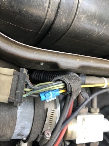
Purple wire is main power running to inline 30 AMP fuse (part of the wiring harness provide with controller) and then to the 12 GA red power wire I ran from starter post.Black and blue run to the fans. Black is ground and I ran it to the front engine bay ground point on the passenger side. Gray wires are to the temp probe. yellow is the ignition signal wire runs to the wiper wires in the cowl. Green comes of the AC compressor.
Contour fan wiring routes to the top and then connects to power and ground wires (Blue and Black) that connect to the controller. I ran the wires around the right side of the radiator and around to the controller.
You can see how nicely the fan fits into the radiator frame and how much space you have without the viscous fan.
This is where I tapped into the black and yellow wiper ignition controlled wire by the wiper motor.
The yellow wire runs over to the blower fan and through the existing pass through up to the controller along the 14 pin wiring bundle.
Thanks for the pics and info, they'll come handy later on, once I start working on this makeover. My "intensive washer reservoir" is long gone so I'll mount the controller in the same location. Looks like a good spot for it and it will be outside the engine bay hot air.
When you say - "the 12 GA red power wire I ran from starter post" you mean the jumper/booster post near the 14pin conn. onpassenger side ?
The aftermarket fan/shroud assy.s are not wired up so I'll have a bit more work to do there but that is not a big deal.
Dr Bob had mentioned in a different post that if you were going to power off the 14 pin connector he recommended upgrading the battery and alternator supply wires.
I decided to run a dedicated wire from starter supply post to the controller to not put additional load on 40 year old wiring.
One thread said the later cars get their fan power directly from the battery so seemed a reasonable approach.

 09-18-2019, 07:10 PM

 ptional