
New Product: 928 Bump Steer Kits
 05-14-2013, 08:47 PM
#31
Addict
Lifetime Rennlist
Member
Lifetime Rennlist
Member
Toe out under compression is actually a good thing helps turn in as you brake hard into a slow corner....Oh right Mark you never saw a slow corner 
Now bring in Ackerman effect as set up on a street car to really confuse things !
Now bring in Ackerman effect as set up on a street car to really confuse things !
 05-14-2013, 09:11 PM
#32
 05-14-2013, 11:16 PM
#33
Man of many SIGs
Rennlist Member
Rennlist Member

 05-14-2013, 11:25 PM
#35
 05-15-2013, 12:27 AM
#36
Nordschleife Master
You are correct.
This seems to be a common misperception that tie rods and control arms must be level.
They infact must NOT be level in a well designed unequal length system like the 928.
This should only be a misperception to those who have no mechanical leanings at all though, I can't believe we see this from people who are selling suspension parts, and this isn't the only case.
The idea of spacing out a single shear tie rod end is horrible, it's among the most basic things to not do when designing suspensions.
While the bump steer kit isn't a horrible idea. The math it takes to actually determine the spacing, is substantial.
As the suspension compresses on a unequal length dual a-arm suspension the rate of camber increases, this is not a linear rate either. So first you must determine this ramp.
Then you need to determine exactly how much compression you will achieve in the corner with the rest of the setup you have, and again calculate what the camber rate is at that time.
You then have to determine how the angling of the tie rods will affect the toe in relation to the camber of the hub. Before you can adjust the spacing and therefore the arc of the tie rod to keep your correct suspension geometry.........
No offense to most people on this list, but I seriously doubt that most of the board could figure this out.
Now lets look at the last statement of Mike's posting.
Now if you go back and look at the picture that was posted (Rob Edwards), of the bumpsteer kit mounted on the white zombie, you can clearly see that instead of a setup like Carl's the person who made this likely put a tapered sleeve into the factory tapered hole, and then put a bolt with rolled threads through the entire assembly. They also did one other thing that is a very wise idea. Put a nice thick heavy washer on the bottom so that if the heim joint wears to the point of failure, it likely will not be able to fall off 100% and will enable the driver enough control to be able to get off the track safely.
Personally, I would take the setup on the white zombie over the other as far as safety is concerned.
I cannot comment on the bump steer kit's requirement as I have never lowered a 928 to worry about this. Though I would imagine that a slight change to the tie rod angles would not be a bad idea. But again there is lots of work to determine as to how much and what is needed!
05-15-2013, 12:34 AM
#37
One thing about Carls pictures that I noticed he took the angles from a tire at full lock, in a full lock camber turn (if there were ever to be something like that) the inner tow would be massive, such as his first pictures.
Just a thought.
Just a thought.
05-15-2013, 01:29 AM
#38
The Parts Whisperer
Rennlist
Site Sponsor
Rennlist
Site Sponsor
Lets look at this in a little more detail.
While the bump steer kit isn't a horrible idea. The math it takes to actually determine the spacing, is substantial.
As the suspension compresses on a unequal length dual a-arm suspension the rate of camber increases, this is not a linear rate either. So first you must determine this ramp.
Then you need to determine exactly how much compression you will achieve in the corner with the rest of the setup you have, and again calculate what the camber rate is at that time.
You then have to determine how the angling of the tie rods will affect the toe in relation to the camber of the hub. Before you can adjust the spacing and therefore the arc of the tie rod to keep your correct suspension geometry.........
No offense to most people on this list, but I seriously doubt that most of the board could figure this out.
Now lets look at the last statement of Mike's posting.
If you look at the pictures posted by Carl in the first post, you can clearly see that the heim joint in the picture, that the threads have been rolled in and are not cut with a tap/die/CNC tool. Then you look at the part that Carl has made, and you can clearly see that it has had cut threads, not rolled. Each sharp edge created when you "cut" threads leads to a stress riser. Rolled threads do not have nearly as many and in ALL cases leads to a much stronger part.
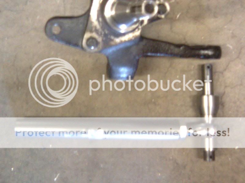
Now if you go back and look at the picture that was posted (Rob Edwards), of the bumpsteer kit mounted on the white zombie, you can clearly see that instead of a setup like Carl's the person who made this likely put a tapered sleeve into the factory tapered hole, and then put a bolt with rolled threads through the entire assembly. They also did one other thing that is a very wise idea. Put a nice thick heavy washer on the bottom so that if the heim joint wears to the point of failure, it likely will not be able to fall off 100% and will enable the driver enough control to be able to get off the track safely.
Personally, I would take the setup on the white zombie over the other as far as safety is concerned.
I cannot comment on the bump steer kit's requirement as I have never lowered a 928 to worry about this. Though I would imagine that a slight change to the tie rod angles would not be a bad idea. But again there is lots of work to determine as to how much and what is needed!
While the bump steer kit isn't a horrible idea. The math it takes to actually determine the spacing, is substantial.
As the suspension compresses on a unequal length dual a-arm suspension the rate of camber increases, this is not a linear rate either. So first you must determine this ramp.
Then you need to determine exactly how much compression you will achieve in the corner with the rest of the setup you have, and again calculate what the camber rate is at that time.
You then have to determine how the angling of the tie rods will affect the toe in relation to the camber of the hub. Before you can adjust the spacing and therefore the arc of the tie rod to keep your correct suspension geometry.........
No offense to most people on this list, but I seriously doubt that most of the board could figure this out.
Now lets look at the last statement of Mike's posting.
If you look at the pictures posted by Carl in the first post, you can clearly see that the heim joint in the picture, that the threads have been rolled in and are not cut with a tap/die/CNC tool. Then you look at the part that Carl has made, and you can clearly see that it has had cut threads, not rolled. Each sharp edge created when you "cut" threads leads to a stress riser. Rolled threads do not have nearly as many and in ALL cases leads to a much stronger part.
Now if you go back and look at the picture that was posted (Rob Edwards), of the bumpsteer kit mounted on the white zombie, you can clearly see that instead of a setup like Carl's the person who made this likely put a tapered sleeve into the factory tapered hole, and then put a bolt with rolled threads through the entire assembly. They also did one other thing that is a very wise idea. Put a nice thick heavy washer on the bottom so that if the heim joint wears to the point of failure, it likely will not be able to fall off 100% and will enable the driver enough control to be able to get off the track safely.
Personally, I would take the setup on the white zombie over the other as far as safety is concerned.
I cannot comment on the bump steer kit's requirement as I have never lowered a 928 to worry about this. Though I would imagine that a slight change to the tie rod angles would not be a bad idea. But again there is lots of work to determine as to how much and what is needed!
Yes the kit I used does have a tapered sleeve.
As for how we decided how much spacing to use we removed the spring and measured the toe change through the wheel movement and we knew how much travel we had as we put a tie wrap on the shock shaft prior to testing.
 05-15-2013, 01:50 AM
#39
Former Sponsor

This was done to my car more than a decade ago and it did help tire wear. I was getting lots of toe out under compression and this helped. I never touched it from day one so I guess that means you might want to take a closer look at things.
I see you sig says expert parts washer so I'm Assuming this is a pic from back when it was mine right
I see you sig says expert parts washer so I'm Assuming this is a pic from back when it was mine right
I got the spherical bearing came from a Craftsman riding lawn mower.
And the bolt and nut came from Home Depot....no silly markings on the head of the bolt to cause any stress risers.
Plenty sturdy.
05-15-2013, 02:03 AM
#40
Nordschleife Master
 05-15-2013, 09:02 AM
#41
I'll see if I can find the tech drawing for the bump-steer bolt that I used. You have to drill and ream your spindle knuckle. It is alot stronger and rids the chance of a bolt taper preventing the stud base from bottoming out on the spindle base, which would allow shank flex.
LOL, the Homie Depot stuff is built like your water pumps, by the same folks too that don't know the meaning of ASTM.
4130 chromoly steel (95,000 lb/in stress)....

LOL, the Homie Depot stuff is built like your water pumps, by the same folks too that don't know the meaning of ASTM.
4130 chromoly steel (95,000 lb/in stress)....
Last edited by xschop; 05-15-2013 at 09:27 AM.
05-15-2013, 09:55 AM
#42
Three Wheelin'
The point of the outter tie rod is dicated by it's intersection with the instant 'swingarm' and inner tie rod.
On a rear steer (steering rack behind spindle) car like the 928, spacing the outter tie rod downward induces toe in.
Porsche did not design the tie rod to be level and moving it somehow puts it "back into it's range" or whatever was said. The tie rod isn't supposed to be level and it can't be by nature of arm travel.
If Mark A did this I realise that it renders whatever I said moot but I stand by everything I said. This topic is not understood by most and unless you actually measure toe throughout the suspension travel and know what you want to see the wheels do, nobody should be doing this blindly, especially with parts of unknown quality.
The proper method to adjust bump steer is to raise or lower the steering rack.
05-15-2013, 10:34 AM
#43
Developer
Thread Starter
This seems to be a common misperception that tie rods and control arms must be level.
They infact must NOT be level in a well designed unequal length system like the 928.
They infact must NOT be level in a well designed unequal length system like the 928.
tie rod angularity even at rest, the Porsche 928 does not.
Feel free to check this fact out, if you have a 928 at stock ride height in your garage, turn your steering wheel hard right or hard left so you can get your head behind it, and have a look for your self. Do not jack up the car. When the curb height is set to factory specs, it so happens that the tie rod arm will be level or very near level on the Porsche 928.
The pictures I posted on page 5 of this thread also confirm this.
Last edited by Carl Fausett; 05-16-2013 at 10:58 AM.
05-15-2013, 10:43 AM
#44
Developer
Thread Starter
This topic is not understood by most and unless you actually measure toe throughout the suspension travel and know what you want to see the wheels do, nobody should be doing this blindly, especially with parts of unknown quality.
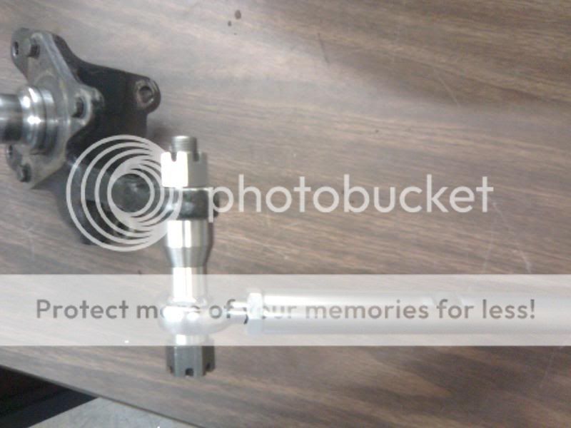
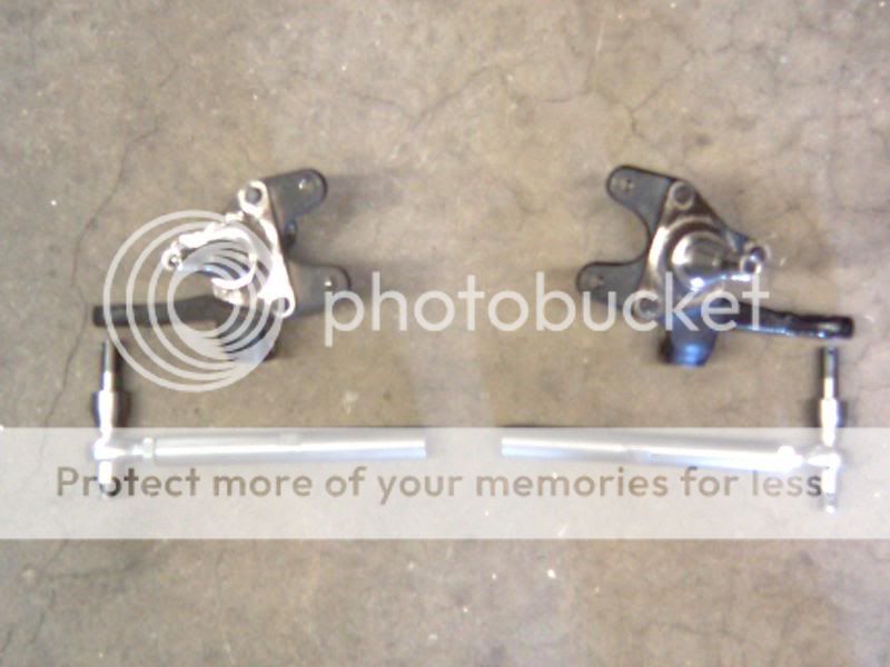
The parts were not made by my own little hands on my own little lathe, either. We commissioned the custom part to be made by a national race parts firm that makes suspension parts for a living. The nuts are DIN spec to match Porsche specification, and yellow-chromate treated to match OEM. The spherical rod ends are from Aurora Bearing. All top quality.
I will only apologize that I did not post the test data with the part. Honestly, as I am not the inventor of the bump steer kit - I am only making a well-accepted part in use for years and years on thousands of Porsches commercially available for the 928, where it was not available before. I honestly thought it was so common and well-accepted that it would be insulting to explain it.
05-15-2013, 10:59 AM
#45
I've seen enough snapped bump-steer bolts to avoid any of the taper-type studs especially the cheap 1/2" crap that is made in the big C. If my 928 gets a lowering, it will get the same treatment here.
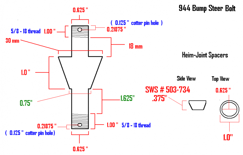
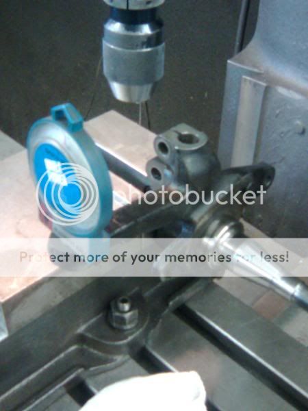
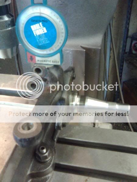
I Drilled the spindle attachment CONCENTRIC 1st with a 39/64 drill bit......
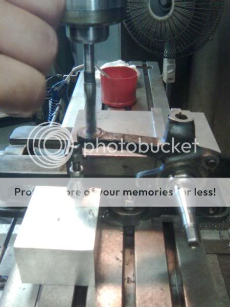
Then I Reamed that drill hole with a new 0.625" (5/8") Reamer for an exact tight slip fit of the 5/8" drop-down bolt
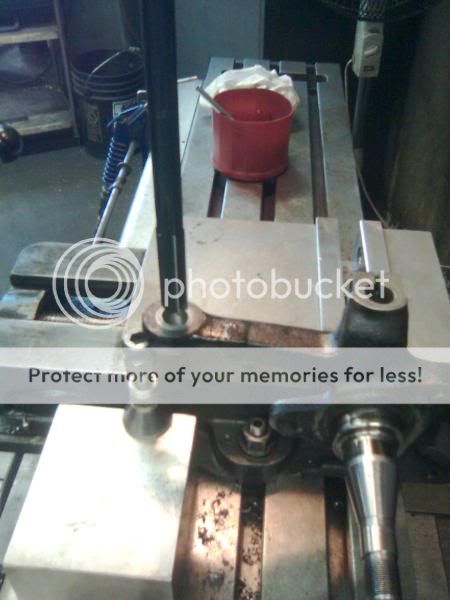
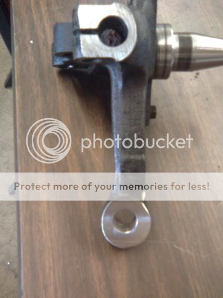
Everything bolts up beautifully and most importantly TIGHT....

I Drilled the spindle attachment CONCENTRIC 1st with a 39/64 drill bit......
Then I Reamed that drill hole with a new 0.625" (5/8") Reamer for an exact tight slip fit of the 5/8" drop-down bolt
Everything bolts up beautifully and most importantly TIGHT....