
S4 intake manifold facts and ideas
 05-12-2013, 08:52 AM
#16
Nordschleife Master
Thread Starter
 05-12-2013, 11:21 AM
#18
Nordschleife Master
Thread Starter
Every time I think about that runner #5 and the stock intake, I get this light bulb go on in my head and I think "we should extrude hone it!" $600 is about to jump out of my wallet. As a countermeasure, I've bookmarked the following page, reproduce in it's entirety here:
http://members.rennlist.com/pirtle/zeng_intake_mod.txt
http://members.rennlist.com/pirtle/zeng_intake_mod.txt
-----Original Message-----
From: 928intl.com [mailto:Mark@928intl.com]
Sent: Friday, March 22, 2002 12:26 PM
To: 928
Subject: [928] interesting dyno results
I recently had my intake manifold extrude honed and my throttle body
enlarged from 75mm to 80mm. The dyno test yesterday show no change on my 6.4 liter motor. My last test 6 months ago showed 414 at the rear wheel and yesterday was actually 410. I was very disappointed to say the least. Next I removed the top of my air cleaner assembly and picked up 15 hp. Next we removed the air cleaner and picked up another 10hp. Now I'm at 436 at the rear wheels but I need to find a better way to provide air to the motor. I wish I had tried removing the air cleaner before because now I'm not sure if the extrude hone did anything.
Mark Anderson
928 International
www.928intl.com
From: Marc Thomas [mmthomas@ix.netcom.com]
Sent: Monday, March 25, 2002 12:04 PM
To: 928
Subject: [928] 928 S4 Intakes
Some years ago we extrude honed, flowed and dyno'd an S4 intake on a stock'er and and the same on early US runners. Note the results on our website! We sell extrude honed intakes for early cars, but not for the S4.....
I did the same test on a stroker a year ago or so, and the result was still no gain, but no loss either. I did not flow the intake pre and post extrudehone as we did previously as it was a "loaner". I did note other interesting features about the extrudehone process that may or may not contribute to the lack of gain on the S4 intake.
As a few of us who have studied the intake carefully have noted and as Kim mentioned, the factory did a damn good job on the intake and it will be very difficult, maybe not impossible, to build a better dual plenum manifold that provides as much overall area under the curve. The design is an engineering tour de force superbly suited for the 928 and its broad torque range.
Excellence is always in the details!
Marc
DEVEK
05-12-2013, 11:34 AM
#19
Nordschleife Master
Thread Starter
All joking aside, it's interesting that the torque peaks have shifted slightly. The dual plenum peak is now at about 3250rpm and the single plenum peak is at about 4450 rpm. That's a ratio of about 1.37, which is larger than the stock ratio of 4100/3150 or about 1.30. It's almost as if the bigger cams and better exhaust are giving us a glimpse that maybe there's some life left in the stock S4 manifold above 5500 rpm.
05-12-2013, 12:05 PM
#21
Nordschleife Master
Thread Starter
That's probably the case.
However, if it's the case, then there must be a massive imbalance between steady state flow between runners. The runners #2 and #3 are pretty much as straight as one could hope, and whatever turns there are are about as long radius as those in manifolds that make really big power in other engines. If cylinders #2 and #3 don't flow enough to make big power, it's not the bends.
This was the original motivation for my question whether anyone has runner specific flow data.
05-12-2013, 06:44 PM
#23
Nordschleife Master
Thread Starter
Other people have identified it as the problem runner: https://rennlist.com/forums/928-foru...ne-spacer.html
I can see why, as I think there are three obvious problems:
1. The 20 cm runner #5 is too short for the 928 rpm range. I think the 30 cm runners are better, but that's just my opinion.
2. The cylinder #5 inlet trumpet is blocked by plenum wall, plenum ceiling, and plenum cover. I have a plan how to modify the main casting and install a spacer permanently to alleviate that problme.
3. The runner #5 also has a sharp, almost 180 degree bend that has a centerline bend radius approximately equal to the runner diameter. See the below picture. The only think I can think of that one could do is to try to somehow widen the runner at the bend, but it's difficult to access.
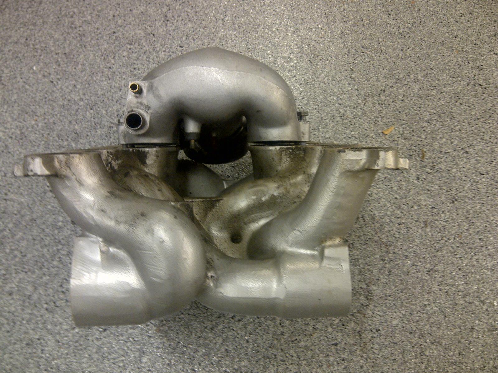
05-12-2013, 08:18 PM
#24
Nordschleife Master
Thread Starter
Here are some predictions about how the flappy closed torque peak rpm changes when various intake manifold parameters are changed. Assumptions include me setting up the spreadsheet correctly.
Predicted impact of changes in the Helmholtz resonator configuration
Intake configuration Resonant frequency rad/s % change in torque peak rpm
Base case 781 0.0%
Intake primary runner length +10% 756 -3.2%
Intake primary runner cross-sectional area +10% 773 -1.0%
Secondary pipe length+10% 756 -3.2%
Secondary pipe cross-sectional area +10% 803 2.8%
Plenum volume +10% 773 -1.0%
Bore diameter +10% 759 -2.8%
Stroke +10% 770 -1.4%
Not huge impacts from anything that is easy to change.
05-12-2013, 09:39 PM
#25
Nordschleife Master
Ok first pic is stage II cams stock exhaust auto, We saw 330rwhp
Second pic is Stage II cams w/ tri-flow, GT, MSDS headers and dual 2.5" exhaust. So far 352 RWHP
We are going to be re-tuning the GT again because I could not get the fueling between 12.2-13.1 I could adjust the cells by even as much as 40 and it would stay at 12.2, then jump to 13.1..... So those numbers are NOT finalized. I was able to get a much better AFR curve on the auto due to the stock exhaust and the LH able to control the injectors giving a much better AFR.
On pic 2 we had trouble as well with the RPM pickup on the dyno. So it was off. The dyno was actually run up to 6200RPM.
05-13-2013, 03:58 AM
#26
Former Sponsor

I'd certainly share my flow bench data....if it was meaningful. My flow bench simply will not "pull" enough air to get really meaningful data out of an intake manifold....at least not enough air to find the inadequacies of this manifold. I have to extrapolate data to get numbers at 10 inches....and
extrapolation just doesn't work well for meaningful data at high flow rates.
I was going to go over and borrow a friends larger flow bench and do some testing.....when I "hit the wall" on Sean Smith's engine, during two solid months of testing.....
Allow me to try to explain....all "power numbers" are plus or minus 4-5 hp......and all "changes' were re-Sharktuned before testing, after original Sharktuning was performed. Sharkplotter did not exist, at this time, and neither did John Speake's "easy to change" chips....all were individually burned eproms.
6.5 liter stroker engine. 968 Intake valves. Ported heads. 928 GTS camshafts at stock specifications Stock exhaust manifolds. Stock intake manifold. High flow cats with x-pipe and high flow mufflers. 19lb injectors. Higher fuel pressure to add additional fuel. 360hp.
Same as above with 30 pound injector and Sharktuning. 360hp.
Same as above with 100 octane race fuel and significantly increased timing. 360hp.
Same as above with GT specification exhaust cams and different exhaust valve springs. 360hp.
Same as above with GT specification intake cams and different intake valve springs. 360hp.
Same as above at a completely different dyno facility. 360hp.
Same as above with a completely different torque convertor design. 360hp.
Same as above with cams advanced 4 degrees. 360hp.
Same as above with cams retarded 4 degrees. 360hp.
Same as above with intake cams advanced 4 degrees and exhaust cams at std. 360hp.
Same as above with intake cams retarded 4 degrees and exhaust cams at std. 360hp.
Same as above with exhaust cams advanced 4 degrees and intake cams at std. 360hp.
Same as above with exhaust cams retarded 4 degrees and intake cams at std. 360hp
Same as above with "intake spacers". 360hp.
Same as above with highly ported intake manifold (no spacers). 360hp.
Same as above with intake spacers and modifications to "blend in" intake spacers. 360hp.
Same as above with 80mm throttle plate. 360hp.
Same as above with highly modified lower plenum (20 hours of welding and porting). 360hp.
Same as above with highly modified intake "bells". 360hp.
Same as above with stock GT exhaust.....just to see if anything might possibly make a change. 340hp.
$2500 worth of dyno testing and two solid months of R&D and changing parts......
Found out that this stuff isn't quite as easy as one might think, reading Rennlist.
Sanity, my wife, and my bank all required a stop to testing.
And with regards to this thread....I do not personally believe that the intake manifold was a significant "restriction" in the above engine.
By God, this stuff is so much fun!!!!
Last edited by GregBBRD; 05-13-2013 at 04:25 AM.
05-13-2013, 04:24 AM
#27
Instructor
Join Date: Oct 2005
Location: Finland
Posts: 137
Likes: 0
Received 0 Likes
on
0 Posts
The S-curve is the worst what comes to flow restriction. You need at least some 20 cm between curves to make flow back to laminar, before next turning.
http://www.waset.org/journals/waset/v69/v69-77.pdf
https://www.ricardo.com/Documents/Do..._vectis_06.pdf
Air does have a mass and therefore it doesn't want to turn quickly, If the diameter of flow path is correct, 98% off flow depends on shape of the flow path, rest 2% is shiny finish. Do not spend time on honing. Also, air want's to flow straight between to points.
The intake track from valve face to opening is very close to 100mm(3,94"). This is what you need to add to get correct intake tube lenght.
Check what Jim Morton did for Dennis Kaos intake post #116: https://rennlist.com/forums/928-foru...the-gap-8.html
If you look the throttlebody, you will immediately see that the driver side turning from TB to oval upstream tube is too tight. Same thing is with turning from oval tube to cylinder #5. The air needs to turn more than 90 degrees there.
Looking back of the bellomouth of #5, you'll see the extra casting which will prevent the air to flow from behind the bellmout to front of it. You can also reduce the diameter of needed bellmouths to help the air flowing from behind. Pay attention to bellmouth radiuses and make them optimal as well as the shape of bellmouth edges. Try to separate the bellmouth edges from sidewalls and so on.. http://blog.intengineering.com/archives/693
You will quickly see that it's not just the S-curve of #5 or #8 which will restrict the flow. The sideplate of plenum is too close to #5, but there is also so much extra casting in bellmouth that you can slightly shortening it. Lot's of PITA grinding, various types of Dremel tools and some flowbench testing needed..
I don't like to speak about amount of the flow, it's rather the flow restriction of plenum which is the problem. Even the #5 is able to flow as much as needed for close 600hp. Why even the stoker engine cannot still produce that amount of hp? When the intake valve opens and piston starts to suck air, the air tends to stretch as it has a mass and don't like to start moving qickly. More you have restrictions in intake path, less is your amount of VE. This is whay late intake valve closing and good inertia effect works so fine.This applies also for FI engines even with the pressurized plenum.
Cheers..
05-13-2013, 08:59 AM
#28
Nordschleife Master
Thread Starter
The S-curve is the worst what comes to flow restriction. You need at least some 20 cm between curves to make flow back to laminar, before next turning.
http://www.waset.org/journals/waset/v69/v69-77.pdf
https://www.ricardo.com/Documents/Do..._vectis_06.pdf
http://www.waset.org/journals/waset/v69/v69-77.pdf
https://www.ricardo.com/Documents/Do..._vectis_06.pdf
The papers find that curved runners are at some rpms better than straight runners. Importantly, they take the intake runner lengths and diameters as constants. The optimal runner parameters may however be different depending on whether the runners are curved or not, much like the optimal intake port diameter is depending on the whether the port is straight or has a sharp turn. I believe that if everything is being optimized jointly, at any given rpm point that you are optimizing a close to perfectly straight runner will have the best results. In these experiments the bends may simply be causing resonance effects that could be produced more efficiently with straight runners but with different geometries.
Check what Jim Morton did for Dennis Kaos intake post #116: https://rennlist.com/forums/928-foru...the-gap-8.html
Looking back of the bellomouth of #5, you'll see the extra casting which will prevent the air to flow from behind the bellmout to front of it. You can also reduce the diameter of needed bellmouths to help the air flowing from behind. Pay attention to bellmouth radiuses and make them optimal as well as the shape of bellmouth edges. Try to separate the bellmouth edges from sidewalls and so on..
You will quickly see that it's not just the S-curve of #5 or #8 which will restrict the flow. The sideplate of plenum is too close to #5, but there is also so much extra casting in bellmouth that you can slightly shortening it. Lot's of PITA grinding, various types of Dremel tools and some flowbench testing needed..
Here's what I am much less certain about. Am I better off reducing the outside diameter of the bellmouth to give it more space to draw in air, or use that same real estate to make the inside of the bellmouth larger and therefore allowing a more gradual taper into the runner? The piece you linked to shows results according to which it's much more critical to get the inside of the runner trumpet right than to raise the trumpet from the floor, although I am sure there's an optimal tradeoff there somewhere too.
I don't like to speak about amount of the flow, it's rather the flow restriction of plenum which is the problem. Even the #5 is able to flow as much as needed for close 600hp. Why even the stoker engine cannot still produce that amount of hp? When the intake valve opens and piston starts to suck air, the air tends to stretch as it has a mass and don't like to start moving qickly. More you have restrictions in intake path, less is your amount of VE. This is whay late intake valve closing and good inertia effect works so fine.This applies also for FI engines even with the pressurized plenum.
One more thing to note: Runner #5 has an expansion in the cross-sectional around that sharp near-180-degree turn. I think it's there to slow down air and to allow air to make the turn more easily. I am wondering if that expansion screws with the pulse tuning, it's going to reflect at least a small inverted sign pulse and then the turn wall itself is going to send a sign preserved pulse. No idea about the answer.
05-13-2013, 09:55 AM
#29
Nordschleife Master
As another data point, while flow testing the heads to my 6.1 liter engine project, we flow tested the S4/GT/GTS intake. Here is a rough summary of the results.
With the end plates on as OEM, using either the straightest runner or the most bent, the flow at 25" was around 220-225 CFM. Moving the plates out 1/4 of an inch gained about 5 CFM. Moving the plates out approximely 3/4 of an inch took the manifold up to the high 240's with the best runner at 250 CFM... again at 25inches. Only about 5-ish CFM more was gained with the plate completely gone.
The mainifold runners gained slightly with mild porting, but not as much as hoped for. Using a simulated 3/4 inch spacer for the end plates, re-shaped horns to the runners and mild porting got the best runner to 280CFM and the worst to 265CFM, showing about a 10 percent flow spread for the manifold.
With all the test porting and flow work done on the OEM manifold, I am now looking to making some sort of new setup before proceding further on my 6.1 engine. I say this as my heads flow 340 CFM at .425" of lift. Restricting such nice heads with the OEM manifold would be a huge waste !
Given the results with the OEM manifold, I cannot see moving forward building an engine that gets restricted by the OEM intake to a point where it's a whole lot of money to simply end up frustrated with the result...
In the mean time, I think I can wake up my 5.4 GTS engine with some cams and tuning and have a nice "hot rod" road car until the intake can be designed and fabbed for the 6.1 liter engine build. I suspect the intake project will be a this coming winter time effort.
$0.02
05-13-2013, 09:57 AM
#30
Nordschleife Master
Thread Starter
I'd certainly share my flow bench data....if it was meaningful. My flow bench simply will not "pull" enough air to get really meaningful data out of an intake manifold....at least not enough air to find the inadequacies of this manifold. I have to extrapolate data to get numbers at 10 inches....and extrapolation just doesn't work well for meaningful data at high flow rates.
6.5 liter stroker engine. 968 Intake valves. Ported heads. 928 GTS camshafts at stock specifications Stock exhaust manifolds. Stock intake manifold. High flow cats with x-pipe and high flow mufflers. 19lb injectors. Higher fuel pressure to add additional fuel. 360hp.
...
Same as above with GT specification exhaust cams and different exhaust valve springs. 360hp.
Same as above with GT specification intake cams and different intake valve springs. 360hp.
...
Same as above with intake cams advanced 4 degrees and exhaust cams at std. 360hp.
Same as above with intake cams retarded 4 degrees and exhaust cams at std. 360hp.
Same as above with exhaust cams advanced 4 degrees and intake cams at std. 360hp.
Same as above with exhaust cams retarded 4 degrees and intake cams at std. 360hp
...
...
Same as above with GT specification exhaust cams and different exhaust valve springs. 360hp.
Same as above with GT specification intake cams and different intake valve springs. 360hp.
...
Same as above with intake cams advanced 4 degrees and exhaust cams at std. 360hp.
Same as above with intake cams retarded 4 degrees and exhaust cams at std. 360hp.
Same as above with exhaust cams advanced 4 degrees and intake cams at std. 360hp.
Same as above with exhaust cams retarded 4 degrees and intake cams at std. 360hp
...
I don't have a wife problem, or to the extent I have it's a different kind of wife problem. She doesn't mind me spending money on the 928 project. however, while I was programming the Helmholtz spreadsheet on Saturday, she order 12 dining room chairs at $850/chair...