When you click on links to various merchants on this site and make a purchase, this can result in this site earning a commission. Affiliate programs and affiliations include, but are not limited to, the eBay Partner Network.
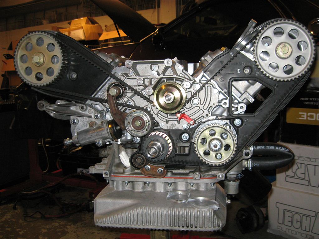
HELP! Need help with an 88’ 928 S4. I am rebuilding the engine and having trouble figuring out how to time the engine. I read online how to set the crank at 45 degrees, I installed both sets of cams in the heads with the arrows facing up, but now how do I get them set at top dead center without damaging the valves . After messing with this for quite some time I got the cam gear mark on the left aligned with the mark on the cam cover housing and the crank at top dead center, but can’t quite get the right cam timing marks lined up with the cover. I’ve tried moving the cam gear one tooth forward, one tooth back but it still does not line up perfectly. I’ve adjusted the belt tension correctly and turned the engine over several times and rechecked alignments, but still cannot get it to match up. Question…What am I doing wrong? I want to make sure I get this right. Any suggestions or guidance would be great. Also I am looking for specs for a M28/42 and how to perform cam timing for this motor. I have found all kinds of manuals online but it is not for this one. Any help would be much appreciated.
The whole reason to set the crank at 45 BTDC is this position allows the cams to be rotated independent of the crank and not have the valves touch the pistons. The factory way to time the cams is to measure valve lift at 20 ATDC using a dial indicator on the #1 and #6 lifter. There is a much easier tool available HERE that doesn't require removal of the cam cover or a dial indicator.
Also unless you know that the cam gears are correctly indexed (adjusted) on the cams then the marks on the cam gears are only a "ball park" setting.
Please find a local that has a PKen 32vr adjustment tool and then you will know exactly where they are.
First, be careful: As Mike mentioned the 45-deg crank position is "safe"-- the pistons are all at mid-travel and the cams can be rotated without risk of damage. However, the timing marks on the cam sprockets will NOT line up when the crank is at 45 BTDC.
With the crank at 45 BTDC, the zero-degree marks on the sprocket will be three teeth to the left of the notch on the cover, as shown on this picture from Dwayne's epic "Timing Belt and Water Pump Procedure w/ Pic's" (in Dwayne's Garage at the NorCal 928 site).
So get the belt on first at the 45-deg marks shown, with the three rotor screws in the middle of their slots. Then rotate the engine clockwise and check the zero-degree marks, the notches at the back of the sprocket should align with the notches on the cover.
Then use Ken's "PK32V'r" tool to do the final alignment, as noted above. You can download the instructions from Ken's website. Mike Frye's manual is very helpful ("User created manual" in little tiny print on that page).
Factory process is very simple once its memorized.
1. Set crank to 45 BTDC and lock it there
2. Install cams and check they rotate nicely etc. At this stage its possible to rotate oil pump with electric drill and pump up all lifters full of oil by rotating cams while oil is pressurized.
3. Turn cams to 0 TDC
4. Release crank and turn it to 0 TDC. When done correctly crank can be safely turned as long as its only turned 45 -> 0 and cams remain at 0 TDC during it.
5. Install cam belt
6. Adjust cam gears by either factory method or Porken's tool.
Geting oil everywhere on valvetrain at step #2 requires special tool. In this case short 22mm hose to connect oil cooler lines. Cam belt is on already while pumping was done before it was installed on this 16V ROW S engine.
I'm still not sure how close you need to be with the rear marks on cam gear relationship to cam cover mark because my (right cam gear is off a half a tooth) and belt tension is correct I've tried several times back and forth. The (front) timing marks on both the cam gears are wide so my question is if one doesn't match up to the back mark but is in the range of the front wide mark is this acceptable. I know after I get passed this point I need to set my cam timing. I have a dial indicator but would like a little help if possible. I believe these are the correct settings (#1 intake should be 1.8mm @ 20 degrees ATDC and #6 intake should be 2.0 @ 20 degrees ATDC). Thanks again for help and patients
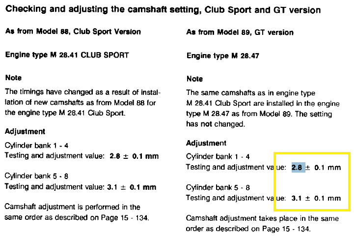
Hi.... Hope u all are doing well, can anyone help me with dial gauge adjustment values corresponding to 20 degree crank angle. From SIT it says for the GT version values are as per attached pic. But I am not sure if the timing values are same for 1993 GTS as well, We all know that engine volume was increased then. Just want to be sure
GTS cams are different, same method but different lift at 20-deg. This is from the '90-93 S4, GT & GTS Tech Spec booklet:
hi... I put back the cam sprocket as per the information & checked the marking on cam sprocket @ crank tdc... Matches up perfect... But while i rotated through crank bolt after installing the belt... I am feeling resistance after rotating the crank around 270 degree( means that I am not able to rotate 1 complete round), I did not proceed further as I was afraid to bend a valve... How it can happen...
Thanks .
Perfect alignment of the cam GEAR notch to the backing plate notch is not the target. The target is the cam itself. It appears you figured that out. The position of the cam gear teeth can vary a bit due to small variations in the geometry of the heads, timing belt system components and the belt. So, the target for the gear is to position it on the belt so it is at the LEAST distance between the gear notch and backing plate notch. The position that is less than 1/2 tooth at TDC is the target for the gears. After accomplishing that, the cam is adjusted to get it right on the "correct" timing. I know for the experts at this, this is very rudimentary, but the first time you approach this system it can be confusing. Carry on.
Hey guys, I found the problem, it was my mistake, someone dropped a nut inside the cylinder.. although it is a surprise & a lesson for me to be extra cautious while doing this job..... I checked with magnet & an endoscope inside the cylinders & found the nut... engine rotates easily now I have to adjust it... I have 2 doubts.
1. While putting the dial gauge which position the engine should be at, is it firing tdc or any other position will work... Want to confirm it
2. How do I stop rotation of cams while adjusting the crank to 20 degree... is there any tool...
Thanks
Your comments suggest you do not understand the essence of the procedure.
There is no reason to stop rotation of the cams - the whole point of the exercise is to ensure inlet cam lift is correct at the specified crank position and then ensure the cam lift at that position is spot on that specified for the cams used. As I recall 20 degrees after TDC is the correct position to set the cams and that with No1 cylinder inlet valves on its firing stroke to time bank 1/4. The procedure is then repeated on the other stroke measuring lift on No 6 cylinder inlet valve[s].
If you are going to time your own cams I would suggest you get hold of a set of the 32VR cam timing kit [see www.liftbars.com]. Very easy to use and no dial gauges needed unless you want to verify accuracy of your installation [ a good thing].

 04-21-2013, 01:44 AM