
Sharktuning issue..
 11-20-2012, 02:03 AM
#16
Rennlist Member
Thread Starter
It looks something resonance related for sure, since it's almost vertical. Almost but not perfectly vertical fits the theory, because I'd assume that the intake manifold air temperature is higher at low load than at high load. The speed of waves (sound) varies slightly depending on air temperature, traveling faster in the hotter air. That would explain the slight angle in the lean spots.
This can be tested. If you set the flappy to be forced open, then the resonances should change and mostly disappear as the pulses combine. Set the ST2 flappy opening and closing to some very large numbers and see if "the red towers of Pisa" disappear.
It could also be that those are spots at which you've lifted off, the deceleration fuel cut off kicks in and the load declines faster than rpm.
If you look at the actual log data, what are the normal conditions in which the lean spots happen. That is, from which direction are you coming from on the fuel map?
To answer this post and Colin's:
I set the flappy hardware back to OEM operation to "see and test". RPM and load values are OEM as well.
I can easily plug the vacuum source to the flappy to be full time open in the AM, no problems. I have 2hrs of my normal mountain plus flat land cruise to do tomorrow to see what this does.
When I hit them, i'm accelerating up into them, and I can set the cruise control on them as well. *stumble stumble stumble*

 11-20-2012, 11:46 AM
#19
Rennlist Member
I am running those injectors as well, but with an FPR and three fuel dampers, in a geometry similar to the stock system including a return line system.
I am eyeballing from the graph resonance lines at 800, 1600, 2400, and 3600 rpm. That would be consistent with fuel system resonance, but it would of course be consistent with many other things as well.
I am eyeballing from the graph resonance lines at 800, 1600, 2400, and 3600 rpm. That would be consistent with fuel system resonance, but it would of course be consistent with many other things as well.
I still like the resonance theory, but I am not sure how to fit it with that data.
A big problem here is too many changes and not enough data.
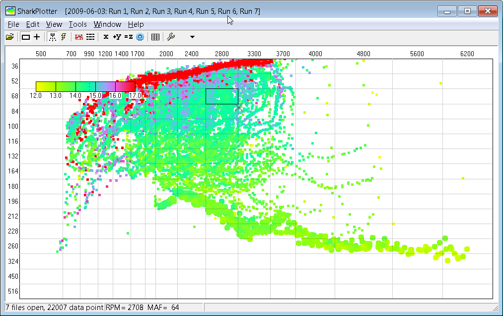
But even a stock setup shows some signs of resonance... here is a plot from our S4 from a couple of years ago with lots of data points. You can see a weak resonance every 300-400 RPM or so. I make resonance lines at 1330, around 1550, 1815, weakly at 2100, 2300, 2660, 3050 and a broad area around 3200 (picking RPM's off the SP plot with the cursor). In this case it only happens at light loads (flappy not active?) and isn't nearly as sharp. And doesn't always show, some days it is not there at all. I've seen this effect on other cars as well, including our GT-- which interestingly went away completely when we got rid of the MAF (with no other intake changes).
 11-20-2012, 12:20 PM
#20
Nordschleife Master
If it's the fuel system resonance, then the resonance rpm should change predictably with the injector pulse width. The closing of the injectors causes the pulse, and the time from the injector closing to the next opening depends on, among other things, on the rpm and load. That's why fuel system resonance rpms aren't exact multiples of some number and at higher loads the resonance rpm would be higher (consistent with the slight angle in the data).
I think the first thing to do is to log the injector pulse width, MAF voltage (or whatever is the best to compute the air mass), and the AFR form the WBO2 censor. Then focus on the area where the problem is clearest, 2400 rpm, and try to keep the car in a steady state. Cruise control on different gears is a great idea. If the measured air flow and injector pulse width at 2400 rpm are both approximately the average of those at 2350 and 2450 rpm, yet the WBO2 shows a lean spot, then I think it has to be fuel pressure fluctuations in the fuel rail caused by resonance.
I think the first thing to do is to log the injector pulse width, MAF voltage (or whatever is the best to compute the air mass), and the AFR form the WBO2 censor. Then focus on the area where the problem is clearest, 2400 rpm, and try to keep the car in a steady state. Cruise control on different gears is a great idea. If the measured air flow and injector pulse width at 2400 rpm are both approximately the average of those at 2350 and 2450 rpm, yet the WBO2 shows a lean spot, then I think it has to be fuel pressure fluctuations in the fuel rail caused by resonance.
11-20-2012, 12:34 PM
#21
Administrator - "Tyson"
Lifetime Rennlist
Member
Lifetime Rennlist
Member
Chatting with Victor at SITM I suggested this if he ever experiences any odd tuning issues (such as this).
IMO everyone with a modified air intake should be using one just to be safe. Keeping the air more uniform is always a good thing.
This isn't a "band-aid" fix like some have mentioned in the past. Manufactures are using them now. My 2003 Yukon has the same straightener in front of the MAF from the factory.
11-20-2012, 12:35 PM
#22
Nordschleife Master
11-20-2012, 01:03 PM
#23
Rennlist Member
Thread Starter
+1
Chatting with Victor at SITM I suggested this if he ever experiences any odd tuning issues (such as this).
IMO everyone with a modified air intake should be using one just to be safe. Keeping the air more uniform is always a good thing.
This isn't a "band-aid" fix like some have mentioned in the past. Manufactures are using them now. My 2003 Yukon has the same straightener in front of the MAF from the factory.
What options exist that match our MAF size?
Or...Jim...live with it for a few bits, then go MAP?
11-20-2012, 01:35 PM
#24
Nordschleife Master
This is $0.02 worth of internet engineering, but I believe that the MAF is responsible only a small fraction of tuning problems that it's been blamed for over the years. It's kind of like the modern version of the saying "90% of carburetor problems are electrical."
For example, the 928 throttle body combines the pulses from eight different cylinders. To me, this means that the pulses must cancel to a great degree. I don't understand how the combined pulses could confuse the MAF, regardless of the cams or whatnot. There's some disconnect between my understanding and what I read on the web about this, and either one is wrong.
The honeycomb ahead of the MAF is not going to hurt, it might even help a little bit. Replacing the wire mesh with a honey comb can work as well as the wire mesh but with less flow resistance. However, I would be very surprised if adding a honey comb in addition to the two stock screens would make a measurable difference to this problem, or any clearly identifiable problem with the 928.
With both screens on feeding the stock 928 intake manifold, I've come across one and only one situation in which the MAF signal may give an incorrect reading. That one situation is when the throttle plate is slammed shut. This creates a pressure wave that cools differently from typical flow, and it may confuse our hot-wire style MAF. Throttle being slammed shut is a very special condition which I believe one can tune around such that the cells visited in this failure mode give sensible results. This is the exception to the "working MAF works perfectly" rule.
Contrast this with the fuel system. The engine batch fires all the injectors at the same time. As the injectors shut, this causes a pulse wave in the fuel system. If fuel pressure is high, the pulse wave is stronger, so this should be a bigger deal with boosted cars that have the fuel-pressure regulator referenced to the manifold pressure. If the injectors are large, the impact of the pulse wave can be large. This is because large injectors are open a very short time at low loads, and the pulse can cover the whole injector opening time. For longer pulses, the injector opening averages over a broader section of the wave. At high loads, the red columns fade away in both Jim's and Jeff's graphs, consistent with the longer injector opening time averaging the fuel pressure over a broader section of the wave.
I am of course just speculating here, what do I know about pulses in fluid -- nothing. Still, it's a better theory than what anyone else has come up with.
11-20-2012, 02:01 PM
#25
Rennlist Member
I think the first thing to do is to log the injector pulse width, MAF voltage (or whatever is the best to compute the air mass), and the AFR form the WBO2 censor. Then focus on the area where the problem is clearest, 2400 rpm, and try to keep the car in a steady state. ...
The question is why. I am not so sure that I buy this turbulence theory, in Jeff's case. For a stock intake, yes: you've got an air filter on one side of the MAF, but that's pretty transparent to airflow. And the transition into the MAF is far from ideal, with sharp corners and airflow coming from two sides-- so yes, turbulence makes sense.
But Jeff has a single long pipe from the SC, and an intercooler just upstream of the MAF-- I would think that's acting as a pretty good air-straightener/diffuser setup. And I don't recall this being an issue with other similar SC intake setups.
But I think taking a careful look at the log data will help answer that question.
11-20-2012, 02:13 PM
#26
Rennlist Member
The other theory is fuel pressure, artifacts related to the dead-ended rails and single damper. That's a large change from the factory setup (and common practice) with flow-through rails and dampers at each end.
I am not saying it is good or bad, and I have no idea if that is related to this problem-- just that when something is different then it needs looking at. The problem is that measuring dynamic fuel pressure is not easy, but if the logs rule out MAF load and Tinj changes, then that might be the next thing to look at.
I am not saying it is good or bad, and I have no idea if that is related to this problem-- just that when something is different then it needs looking at. The problem is that measuring dynamic fuel pressure is not easy, but if the logs rule out MAF load and Tinj changes, then that might be the next thing to look at.
11-20-2012, 02:18 PM
#27
Nordschleife Master
The other theory is fuel pressure, artifacts related to the dead-ended rails and single damper. That's a large change from the factory setup (and common practice) with flow-through rails and dampers at each end. I am not saying it is good or bad, and I have no idea if that is related to this problem-- just that when something is different then it needs looking at. The problem is that measuring dynamic fuel pressure is not easy, but if the logs rule out MAF load and Tinj changes, then that might be the next thing to look at.
"Contrast this with the fuel system. The engine batch fires all the injectors at the same time. As the injectors shut, this causes a pulse wave in the fuel system. If fuel pressure is high, the pulse wave is stronger, so this should be a bigger deal with boosted cars that have the fuel-pressure regulator referenced to the manifold pressure. If the injectors are large, the impact of the pulse wave can be large. This is because large injectors are open a very short time at low loads, and the pulse can cover the whole injector opening time. For longer pulses, the injector opening averages over a broader section of the wave. At high loads, the red columns fade away in both Jim's and Jeff's graphs, consistent with the longer injector opening time averaging the fuel pressure over a broader section of the wave."
That is about the resonance in the fuel rail, not in the intake manifold.
These are not just decorations:

 11-20-2012, 03:17 PM
#29
Rennlist Member
Thread Starter
Ya..I will have 2hrs of driving this afternoon..a normal day.
1/2 up 4000' of curvy mtn road, 1/2 flat highway where I can set cruise at the bad points/etc as directed.
1/2 up 4000' of curvy mtn road, 1/2 flat highway where I can set cruise at the bad points/etc as directed.
11-20-2012, 05:44 PM
#30
Nordschleife Master
The question is why. I am not so sure that I buy this turbulence theory, in Jeff's case. For a stock intake, yes: you've got an air filter on one side of the MAF, but that's pretty transparent to airflow. And the transition into the MAF is far from ideal, with sharp corners and airflow coming from two sides-- so yes, turbulence makes sense.
But Jeff has a single long pipe from the SC, and an intercooler just upstream of the MAF-- I would think that's acting as a pretty good air-straightener/diffuser setup. And I don't recall this being an issue with other similar SC intake setups.
But Jeff has a single long pipe from the SC, and an intercooler just upstream of the MAF-- I would think that's acting as a pretty good air-straightener/diffuser setup. And I don't recall this being an issue with other similar SC intake setups.
Also Murf does have honeycomb in his 90 which leads into the MAF......
With my turbo car prior to converting to VEMS with MAP sensing instead. I would get one spot where about half the time it would create a judder at one set RPM. I narrowed it down to the MAF signal going wonky (right as I maxed it out
 ).
). A good portion of the factory MAF's these days come from the factory with the honeycomb, and their wires are much more protected than ours.
Jeff maybe look for a piece from here http://www.hongzan.net/html/Products/Honeycomb_Core/