When you click on links to various merchants on this site and make a purchase, this can result in this site earning a commission. Affiliate programs and affiliations include, but are not limited to, the eBay Partner Network.
What about removing the rear 5 mph shock absorbers and aluminum protection bar under the bumper cover and installing a 3" square steel tube with a receiver welded in the middle behind the flip down license plate?
From what I see you could actually get in there to install and remove it without taking off the bumper cover (after the initial fabrication and instillation adventure).
Should be done this week, powder coated..and on the car hopefully next weekend, time allowing.
There are a few significant issues with the pictured one thats been around. No gusseting at the mount, and there's even a crack in the photos floating around where it failed.
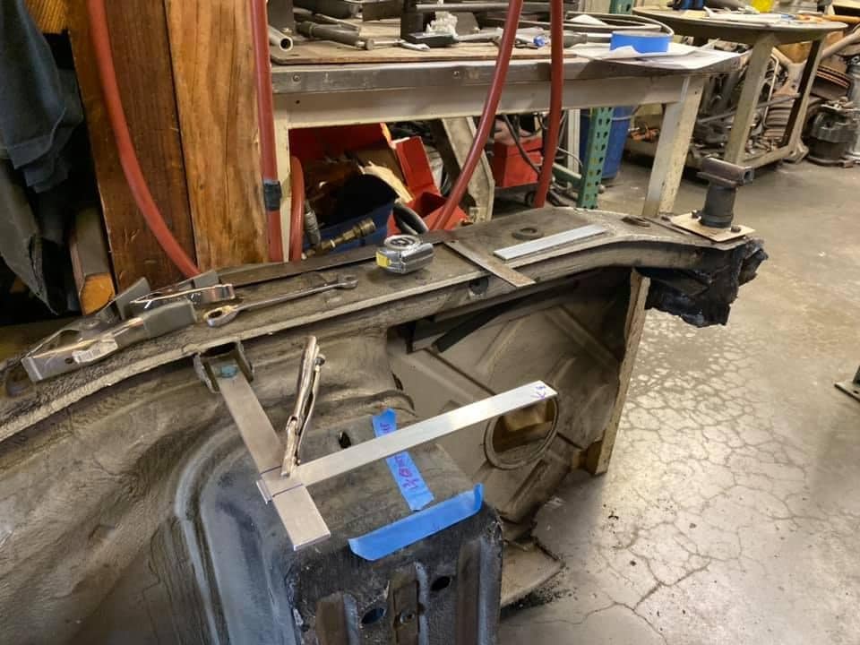
Going to move the receiver plate back another 1/8" to more comfortably clear the bumper lip you see there, But..we ended up smack on where we expected to from using a chunk of a car I cut up earlier this year, with the strips of aluminum marking where in space the lower bumper lip center and location was from the chassis. We cleared the bumper straps (92850527902) and the muffler hangar may require a teeny weeny adjustment.
Just got tired of years of talking...and decided Yesterday AM to do it. Two 12-6pm days invested so far.
There are a few significant issues with the pictured one thats been around. No gusseting at the mount, and there's even a crack in the photos floating around where it failed.
Speedtoys,
Looks like you're off to a good start. I'm excited to see how this turns out, and what the final assembly and tie-in points are.
As for the crack you mention, Are you referring to the pics I posted earlier in this thread? If so, I can guarantee those are shadows and not cracks. Where do you believe that the original is missing/needs gusseting? I agree there are some things that I would change from the original design, but overall I think the original hitch as a very robust system.
Since my 85 (with the hitch installed) got T-boned, I will eventually be pulling it, but a bit low on the priority list at the moment. I have thought of either replicating it with my desired changes or modifying it, before installing on my 86.5, but again it may be a while. The main change I'm looking at incorporating is changing to a standard receiver in place of the proprietary Euro coupler, so that I can mount a bike rack. the other change that I would consider, though it only impact the installation on the car is to change (reverse) mounting bracket on the right rear bumper shock so the hitch could be raised up then slid left into position instead of having to remove the bumper shock to get it into place. I think this change would allow for installation without removing the bumper cover, so the only thing that would be required would be to drop the fuel tank for the install.
That is a shadow. There is absolutely no crack there. The plate that attached st tube to the bumper mount is formed so there is a 90 degree bend in the bracket that is casting that shadow. The fore/aft bracing extends all the way forward past the fuel tank, which is what drives the removal of the fuel tank for install.
That is a shadow. There is absolutely no crack there. The plate that attached st tube to the bumper mount is formed so there is a 90 degree bend in the bracket that is casting that shadow. The fore/aft bracing extends all the way forward past the fuel tank, which is what drives the removal of the fuel tank for install.
Then we disagree.
Thats most ceertainly a crack, theres nothing there with light from that direction to cast -that- shadow, to identify as a metal fatigue crack. It even extends into the weld itself.
No way, IMHO, and my fabricators opinion, is that a shadow...there are sharp lines, surfaces, and patterns that match _so_ perfectly, for this to be a shadow (from nothing in front of it) to be a crack.
It's a crack.
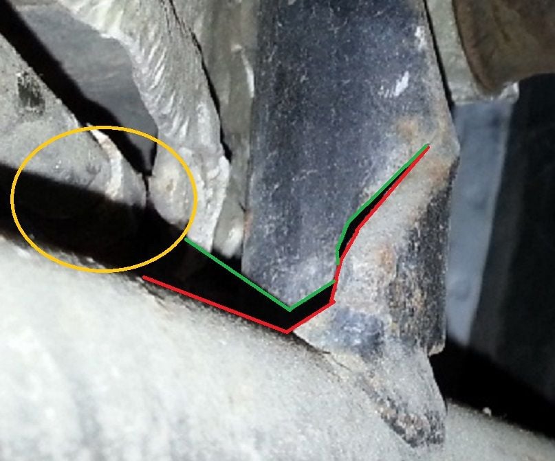
You can see why its there, in the drawing and image here below.
ALL of that stress is in the attachment of the reinforcement down to one small tab..with a big fat weld on it.
The other 90% of the attachment to the mounting bracket is not sharing in any of the work here.
As a dual major in metallurgical and mechanical engineering, and someone who has supported a major airline doing failure analysis and accident investigation (for example), I can verify that without a doubt that is a shadow caused by the flash on my phone not being concentric with the camera lens. The small tab is what is causing the shadow that you are trying to identify as a crack. If you notice the horizontal tube is also causing a shadow which extend up across the mounting bracket as well as along the bottom edge of the body and across the fuel tank vent line.
To help visualization, the red line is the edge of the hitch assembly illuminated by the phone flash. the green line indicates the shadow edge caused by the hitch assembly which corresponds with the area below the red line which has the flash illumination blocked by the hitch. The orange circle is on the area where the tube shadow is crossing the fuel tank vent line. In this area, if you zoom in, you can actually see that the vent line didn't crack of but is faintly visible in the darkness of the shadow.


 09-06-2019, 01:09 AM