


Temp I testing
Thread Starter
Addict
Lifetime Rennlist
Member
Lifetime Rennlist
Member
Joined: Jul 2007
Posts: 4,539
Likes: 4
From: Germany
It works fine, that is the temp gauge does, but what are good resistance values for the Temp I sensor? I measured and got 623 Ohm between both pins and infinite resistance between each of the pins and ground.
Under the Lift
Lifetime Rennlist
Member
Lifetime Rennlist
Member

Joined: Mar 2002
Posts: 18,648
Likes: 52
From: Buckeye, AZ
This sensor works on a change in resistance between the pins to provide engine temp signal to the instrument panel gauge. 623 ohms is higher than the stated range for temp I and would be a very cold temp. Does your gauge stay pegged at the low end?
Under the Lift
Lifetime Rennlist
Member
Lifetime Rennlist
Member
Joined: Mar 2002
Posts: 18,648
Likes: 52
From: Buckeye, AZ
Yes, in a book on the diagnosis of the 89 instrument cluster that is on Jim Morehouse's Tech Pub CD. There is a test procedure that allows you to read out the values it is seeing on the instrument panel.
Thread Starter
Addict
Lifetime Rennlist
Member
Lifetime Rennlist
Member
Joined: Jul 2007
Posts: 4,539
Likes: 4
From: Germany
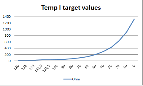
Temp I target values.png
Trending Topics
Under the Lift
Lifetime Rennlist
Member
Lifetime Rennlist
Member
Joined: Mar 2002
Posts: 18,648
Likes: 52
From: Buckeye, AZ
Yes, could be normal. I thought there must be some malfunction or you wouldn't ask. Anyway, you can compare resistance and gauge readings to an IR gun on the water bridge.
Rennlist Stories
The Best Porsche Posts for Porsche Enthusiasts

Porsche Reveals Coupe Variant of the Electric Cayenne With a Fresh Look
Verdad Gallardo
10 Porsche Colors That Have More Personality Than Most People
Verdad Gallardo
Guntherwerks' Final Speedster Creation Is the Ultimate Porsche Restomod
Verdad Gallardo
10 Reasons I Hate Going to the Porsche Dealership (& the 1 Reason I Stay)
Joe Kucinski
Porsche Shakes Up The N�rburgring Lap Record Table Once Again
Verdad Gallardo
6 Ways the Porsche 911 GT3 S/C Redefines Performance
Joe Kucinski
10 Wildest Homologation Specials Porsche Ever Sold
Verdad Gallardo
Super Rare RUF BTR III Comes Out of Hibernation, Looking For a New Home
Verdad Gallardo