

Why Not Cross Tri-Y's (180 deg header alternative)?
 01-02-2012, 02:18 PM
#16
Burning Brakes
Thread Starter
Thanks for all the links. More to consider/verify!
Last edited by hernanca; 01-02-2012 at 03:58 PM. Reason: Clarity. Links.
 01-02-2012, 02:47 PM
#17
Burning Brakes
Thread Starter
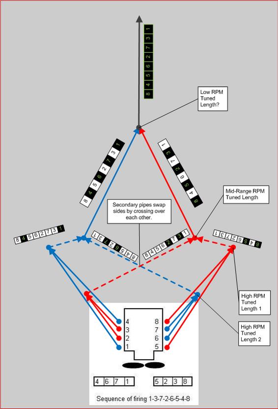
Edit: Adding diagram for 180-degree header exhaust pulses.
The biggest difference between 180 degree headers and what I am suggesting seems:
Like the Tri-Y system, all collectors in my suggestion are 2x1's with, at least (but often more), 180 degrees between consecutive pulses
vs.
180-degree headers have 4x1 collectors, with 180 degrees between every single consecutive pulse in the collection
Last edited by hernanca; 01-02-2012 at 05:11 PM. Reason: Added diagram.
01-02-2012, 07:01 PM
#18
Rennlist Member
I remember Tom's headers. All I could think of was how long the primaries were.
Not exactly tuned for top end RPM.
I'd say 180's given the packaging restrictions are a waste of time on our 928's.
But then, I haven't seen before/after dyno charts.
Not exactly tuned for top end RPM.
I'd say 180's given the packaging restrictions are a waste of time on our 928's.
But then, I haven't seen before/after dyno charts.
01-02-2012, 07:58 PM
#20
Nordschleife Master
Pipemax is excellent software, and with good numbers as input makes very good estimates of results so various designs and lengths can be tried. What I found hard was understanding what all the input numbers were and what values I should use. Rather than hijack this thread I think I will start a new Pipemax on the 928 thread.
https://rennlist.com/forums/928-foru...r-a-928-a.html
https://rennlist.com/forums/928-foru...r-a-928-a.html
01-03-2012, 12:27 PM
#22
Rennlist Member
No one has every challenged the effectiveness of Devek level 2 headers but if these work well on a big stroker like Louie Ott's 600 rwhp motor why would a 5 litre motor turning out half the power require an exhaust of the same inside diameter? Surely the geometry is the critical element [i.e. the distance at which the primaries merge into each other or then crossover?
A tuned exhaust system is only optimal at one frequency [or harmonic thereof]
Is your calculation looking at the headers as a module within a total exhaust system or is it looking at them as a standalone item [as a matter of interest]?
The trouble with process engineering software programmes is you have to know what you are doing when you use them as garbage in = garbage out. If you are fully knowledgeable about how to use this software and confident in the accuracy of your input data pack great- and well done to you.
I suspect you are onto something here. If so, can you take it to the next level and define what needs to be done to the MSDS design to make it effective? Would they be interested to modify their design?
Regards
Fred
 01-03-2012, 05:28 PM
#23
Burning Brakes
Thread Starter
I don't know about the MSDS headers, but the Devek Level II's have the primaries oriented so that, theoretically, this would work out. However, I also have it on good authority (but not Marc Thomas himself) that cutting off the collectors of a perfectly good set of Devek Level II headers would not only be blasphemous, but would also likely release tension on those primaries such that the ends would wind up pointing in several differing directions.
Here is what I mapped out on the Devek Level II's (using AO's image), before I was brought to my senses:
06-05-2013, 04:22 AM
#24
Nordschleife Master
Bumping because I am still thinking about it. With two Y's on each bank, only two pipes need to be routed on each side through the pinch of the engine bay. Seems to me that should greatly reduce the bends and convolutions required in a 4/1 so it should flow better even if tuning is less ideal.
BTW I haven't put much time into it, but a moderate amount and I haven't made any real progress in figuring out all the parameters that Pipemax wants. Anybody with more knowledge care to share some of that data? If I get more ambition I would flesh it out some more maybe in the pipemax support forums and consider having a set of headers made to test if the numbers seem at all promising.
BTW I haven't put much time into it, but a moderate amount and I haven't made any real progress in figuring out all the parameters that Pipemax wants. Anybody with more knowledge care to share some of that data? If I get more ambition I would flesh it out some more maybe in the pipemax support forums and consider having a set of headers made to test if the numbers seem at all promising.
06-05-2013, 09:25 AM
#25
Burning Brakes
Thread Starter
dangler,
Since posting, I came across ONE other person considering this: a gentleman by the name of Mike Trusty which was putting them on a Pantera and then on a GT40. He had talked to Burns Stainless about it, and they helped him with the dimensions for his motor, and mentioned they plan to try the arrangement on some boat motors. I emailed with him, and below is his contact information, in case it helps. He actually used to own a 928, and loves them!
I hope to implement this setup some day, but it is not on my priority list at the moment.
Mike Trusty Engineering
e-mail: miketrusty@msn.com
15119 Gorgeous View Trail
Little Rock, AR 72210
Ph: 501-224-9013
Fax: 501-421-0151
Last edited by hernanca; 06-05-2013 at 09:51 AM. Reason: Added e-mail contact info.
06-05-2013, 10:38 AM
#27
Nordschleife Master
Why not do two double-y's, one for each side, and then a 4-to-1 merge collector at the spot where the H-pipe and the cats usually are? That would mean short primaries and then very long secondaries. But the 4-to-1 collector would see equally spaced pulses.
06-05-2013, 11:03 AM
#28
Nordschleife Master
The firing order is 1-3-7-2-6-5-4-8-1-3-7-2-6-5-4-8.
Shouldn't you combine 1+2 and 3+4 on the passenger side, instead of 1+4 and 2+3? With 1+2&3+4, the minimum pulse spacing is three. With 1+4&2+3, the minimum pulse spacing is two. To me, three is more than two.
On the driver side, it makes sense to combine 7+5 and 6+8. 6+7 has only two step spacing, so you don't want to combine those.
I understand that you would get it all to work out after the cross-over with your primary Y setup, but isn't the two step spacing going to give you trouble at the first Y?
1+2, 3+4, 5+7, and 6+8 make the most sense for the first Y. However, you can't combine those to a perfectly equally spaced pulsing in any way with two Ys. It might be possible to bring those four pipes into a single 4-to-1 collector, but where would you put that on a catted car?
Have I misunderstood something here about headers or the firing order?
06-05-2013, 11:42 AM
#29
Burning Brakes
Thread Starter
The firing order is 1-3-7-2-6-5-4-8-1-3-7-2-6-5-4-8.
Shouldn't you combine 1+2 and 3+4 on the passenger side, instead of 1+4 and 2+3? With 1+2&3+4, the minimum pulse spacing is three. With 1+4&2+3, the minimum pulse spacing is two. To me, three is more than two.
On the driver side, it makes sense to combine 7+5 and 6+8. 6+7 has only two step spacing, so you don't want to combine those.
I understand that you would get it all to work out after the cross-over with your primary Y setup, but isn't the two step spacing going to give you trouble at the first Y?
1+2, 3+4, 5+7, and 6+8 make the most sense for the first Y. However, you can't combine those to a perfectly equally spaced pulsing in any way with two Ys. It might be possible to bring those four pipes into a single 4-to-1 collector, but where would you put that on a catted car?
Have I misunderstood something here about headers or the firing order?
Note that Mike Trusty, assuming he has a Ford 351 in his Pantera, selected the same combination as I did (not proof, of course, but it is encouraging).
06-05-2013, 12:23 PM
#30
Rennlist Member

When exhaust pulses are considered to be 180 it is usually with reference to one cycle of the ignition system sequence so in effect it would be 360 degrees of the crank on a 4 stroke engine. The easiest way to visualize this is in reference to the distributor (provided a single distributor system, dual distributors complicate this visualization).
The reason the Tri-Y works well on the inline 4 is that it is a flat plane crank. Your pairing would work well on a flat plane V8 as well, but with a cross plane crank the 180 degree firing cylinders are on opposite banks. For a flat plane crank the firing order would be something like 1, 7, 2, 5, 4, 6, 3, 8. So from this you can now see that you would get 180 firing cylinders paired using the Tri-Y exhaust. On a cross plane
To truly get 180 pairing on our engines you would have to pair (1, 6), (3, 5), (7, 4) and (2, 8).