
Why Not Cross Tri-Y's (180 deg header alternative)?
 01-02-2012, 12:48 AM
#1
Rennlist Member
Thread Starter
I likely won't get to do this on the silver car anytime soon. I already have a pretty decent exhaust system with Devek Level II headers and Magnaflows. However, if I was building an exhuast system from scratch, this is what I would seriously explore.
For me, the ideal exhaust system for our cars is a 180-degree header setup. If done right, it supposedly offers the most power. However, there are the limitations of packaging these "snakes" under the car - though because of how our transmission sits all in the back, we have a little bit less restriction than others. Still, there are packaging/fitment constraints.
Many folks consider Tri-Y exhaust systems, since these tend to yield more mid-range power, and may be best for non-race, street 928's, especially with automatic transmissions.
So, I was toying with both these ideas, diagramming out exhaust pulses, and realized that if I took one appropriate secondary from each side of a Tri-Y set-up, and swapped it to the other side, I would end up with something very close to a 180 degree header set-up. I looked on the internet and in the respected peformance books, and did not see anything like this, and so I am wondering why not? Is it because, for the trouble of crossing over the secondaries, one might as well do the "snakes" of a 180-degree set-up?
I will attach a diagram of what I mean as soon as I clean it up a bit for general consumption. (Edit: diagram attached).
Feedback and thoughts are welcome, and if someone wants to take this further, I would love to see it. At some point I would like to work with the Burns Stainless calculator to see what it might have to say, if it can even handle this combo. Packaging/fitment will, as always, be a constraint, I'm sure, but this set-up seems more doable than a 180-degree "snakes" set-up.
Last edited by hernanca; 01-03-2012 at 09:43 PM. Reason: Clarity.
 01-02-2012, 12:58 AM
#2
Rest in Peace
Rennlist Member
Rennlist Member
Join Date: May 2006
Location: Bird lover in Sharpsburg
Posts: 9,903
Likes: 0
Received 2 Likes
on
2 Posts
I wonder if there is ample clearance to do a set of them under your car, or any street driven 928 for that matter.
I think it has been done before, but I am not sure.
I think it has been done before, but I am not sure.
 01-02-2012, 01:08 AM
#4
Rennlist Member
Thread Starter
Yes, Cloutier's system is the 180 degree set-up. I have heard the weight issue brought up - something I had not considered until it was mentioned (more piping => heavier), and I understand the concerns for fitting it under the car (the Cloutier systems I have seen pictures of have nasty looking scrapes.
What I am talking about is an alternative to this, which I believe would be easier to fit under the car.
Adding more diagrams to show what I mean. (Edit: added diagram - note that the secondaries only have 3 places where they must cross over each other (burgundy vs. black lines). Depending on what the tuned lengths might be, these cross overs may be able to take place where the Cats usually sit. (Please ignore that the diagram is showing a purposefully unequal overall SYSTEM set-up. I'll get a better diagram )).
)).
Edit 2: added Tri-Y set-up that Mark Anderson had at one time. Note where the secondaries are meeting. What I am asking is, why not have the appropriate secondaries swap sides? Two secondaries tuck as close to the body as possible, and the other two dip down only as much as they have to. Two planes, as deep as the two secondaries. Maybe even weld them together where they cross, so that they can be as close as possible (same as what was done to the side-by-side magnaflows under the silver car).
What I am talking about is an alternative to this, which I believe would be easier to fit under the car.
Adding more diagrams to show what I mean. (Edit: added diagram - note that the secondaries only have 3 places where they must cross over each other (burgundy vs. black lines). Depending on what the tuned lengths might be, these cross overs may be able to take place where the Cats usually sit. (Please ignore that the diagram is showing a purposefully unequal overall SYSTEM set-up. I'll get a better diagram
)).Edit 2: added Tri-Y set-up that Mark Anderson had at one time. Note where the secondaries are meeting. What I am asking is, why not have the appropriate secondaries swap sides? Two secondaries tuck as close to the body as possible, and the other two dip down only as much as they have to. Two planes, as deep as the two secondaries. Maybe even weld them together where they cross, so that they can be as close as possible (same as what was done to the side-by-side magnaflows under the silver car).
Last edited by hernanca; 01-03-2012 at 09:54 PM. Reason: Added notes to Anderson Tri-Y image.

 01-02-2012, 01:35 AM
#7
Rennlist Member
Thread Starter
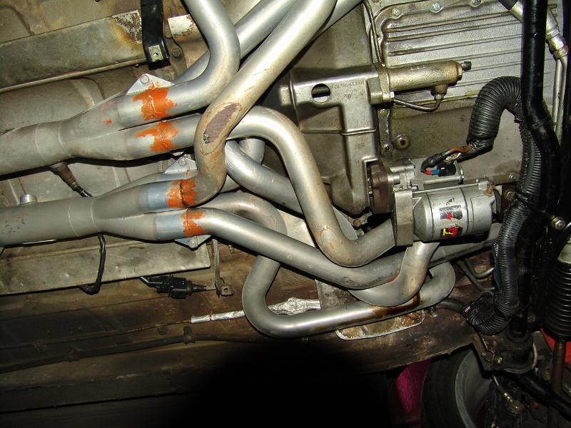
Here is a picture of the Cloutier 180 degree set-up.
In the Tri-Y set up that I am suggesting, there would never be a 4-into-1 collector. ALL the collectors would be 2-into-1.
I just have not seen or heard of anyone trying this set-up, where the Tri-Y secondaries are swapped.
(Edit: attached another diagram of what I mean. Numbering indicates primary pipes which merge 2-into-1 into the four total Secondaries. Then one appropriate secondary from each side swaps to the other side, to join 2-into-1 to create two tertiary pipes. The tertiary pipes can continue as dual exhaust, or join to become a single exhaust pipe to the tip.)
Last edited by hernanca; 01-02-2012 at 01:55 AM. Reason: Added image.
Trending Topics
01-02-2012, 02:53 AM
#8
Nordschleife Master
I've been thinking something similar (time to start worrying), but with the first Y's short enough that only two pipes per side fit through the tight spots. My notion was to make the arms of each Y the same length, but not necessarily the same as the arms of other 3 Y's, then do the length compensation with the 4 pipes under the car into a 4x1 merge. I know nada about exhaust so maybe better to go 4x2 then 2x1 and 2x1, could be pretty flat?
Here is a link to some excellent software.
http://maxracesoftware.com/pipemax36xp2.htm
Make it in stainless and we can have slip fits and skip flanges.
Here is a link to some excellent software.
http://maxracesoftware.com/pipemax36xp2.htm
Make it in stainless and we can have slip fits and skip flanges.
01-02-2012, 03:31 AM
#9
Nordschleife Master

 01-02-2012, 04:42 AM
#10
Instructor
Join Date: Oct 2005
Location: Finland
Posts: 137
Likes: 0
Received 0 Likes
on
0 Posts
Hmmm, that would work if you can calculate and make all the primary lenght's just right. Another thing is that how much more you'll get versus the effort and price of it... Love to see new ideas and thoughts 
There are also perhaps too many bendings on Coultiers 180 degree headers, which may limit the hp and torque output somewhat. More bendings is more turbulence, less flow, slower velocity and therefore less scavenging.
Following are some links, which will tell more about flow models in tube bendings. Interesting thing is that different tube lengths before and after bending does have great infulence of how the tube is flowing. (Use google toolbar translator facility to change the written language(Swedish) to English, works just fine)
http://www.topplocksverkstan.se/FLODESMODULEN.html
http://www.cartage.org.lb/en/themes/...daryLayers.htm
I have also played with Pipemax at some time and quite soon found, that my MSDS collector length is way too short to make any torque at low end and max. hps are tuned way too high rpms for daily usage.
http://www.carcraft.com/techarticles...s/viewall.html
There seems to be solution also for this issue: http://www.coneeng.com/collectors.html
I'm going to replace the old style straight collector with conical colletor and welding 3-hole 2,5" flange to end of collectors 2,5" output. Rest of the exhaust will be 2,5" with Ott-style )(-pipe
Rich Graig from Cone Engineering told me, that if your exhaust piping is 2,5", there is no need for reverse cones to step up and reduce again. They have also tested this kind of combination and it showed minimal improvements over single conical collector and 2,5" flange at end of it. Messing around with too complex collector implemenation may also cause reversion back to cylinder..
Pipemax is also able to calculate the correct X-over distance from end of primary pipes. However, it assumes that best place is just in the middle of total calculated exhaust piping length. Larry Meaux(pipemax developer) told me, that you can use any of the exhaust pulse harmonics for the place of X-over. In my S4 case, best place is if you divide the given X-over distance by two.
Then you are still able to install high flow cats between headers output and X-over. Similar combination, what Louis Ott has done: http://www.performance928.com/cgi-bi...ss_parent=1128
Just for the general interest, moving X-over position around 2", will shift best powerband around 1000rpm or more. That can be easily verified by Pipemax..
Just my two little cents,,
Simo
01-02-2012, 05:59 AM
#11
Nordschleife Master
I know of a pretty good design for a merge pipe.
<<<<<<<
<<<<<<<
Take a look at the exhaust system Greg Brown made with the X at the rear back by the battery box, it makes SERIOUS torque.
I wasn't "real" concerned with the specific primary length, the arms of the Y, since its a bit different for the two Y's in 944 headers, which I figure by now must be pretty well optimized. As long as both arms of each Y are the same it should be easy to make the 4 intermediate pipes the right length so the distance from merge to all cylinders is equal.
Basic idea I had was that the Y's are connected to cylinders as far apart in the firing sequence as is practical for being on the same side so that the flows don't interact much, but I have no idea how that might work.
OTOH maybe its simple enough not to be too costly, and fewer and less sharp of bends should improve flow.
Link I think to Gregs new exhaust.
https://rennlist.com/forums/928-foru...sentation.html
<<<<<<<
<<<<<<<
Take a look at the exhaust system Greg Brown made with the X at the rear back by the battery box, it makes SERIOUS torque.
I wasn't "real" concerned with the specific primary length, the arms of the Y, since its a bit different for the two Y's in 944 headers, which I figure by now must be pretty well optimized. As long as both arms of each Y are the same it should be easy to make the 4 intermediate pipes the right length so the distance from merge to all cylinders is equal.
Basic idea I had was that the Y's are connected to cylinders as far apart in the firing sequence as is practical for being on the same side so that the flows don't interact much, but I have no idea how that might work.
OTOH maybe its simple enough not to be too costly, and fewer and less sharp of bends should improve flow.
Link I think to Gregs new exhaust.
https://rennlist.com/forums/928-foru...sentation.html
Last edited by danglerb; 01-02-2012 at 06:15 AM.
01-02-2012, 12:20 PM
#12
Race Director
Damm.....that looks complicated.................................................
It would have to be an impressive gain to justify all the extra work vs normal headers.....
For example here is the dyno gain I got from a proper single 3.5" system vs a modified 1984 USA single 2.25" system.....
It would have to be an impressive gain to justify all the extra work vs normal headers.....
For example here is the dyno gain I got from a proper single 3.5" system vs a modified 1984 USA single 2.25" system.....
01-02-2012, 01:41 PM
#13
Rennlist Member
Thread Starter
I would be very happy with what looks like a 20 HP and 25 ft.lbs torque gain you show there.

The diagram just looks complicated because I tried to make it clear...

Here are two more diagrams, showing a traditional 4x1 header set-up, and a traditional Tri-Y set-up. Notice the bunched up pulses found in the traditional set-ups. From what I understand, the collectors need to be designed to handle that, though they would be different types of collectors: a single 4x1 per side for traditional headers and 3 2x1's per side with traditional Tri-Y's. In what I am suggesting, the collectors would be 3 2x1's per "side" as with Tri-Y's, but are not constrained by bunched pulses in their design, and so the collector design can be better focused on the scavanging effect, and I believe also made less abrupt thus broadening the pulse tuning effect as well.
01-02-2012, 01:54 PM
#14
Rennlist Member
Thread Starter
I suspect it will require just as much figuring as with an equal length system, if not more so, since each RPM "sweet spot", given by a particular collector placement, can have corresponding detrimental effects elsewhere in the RPM range. If the detrimental effects are minimal, and the multiple sweet spots can be designed to complement those detrimental effects, it may work out quite well.
Thanks for the link to Pipemax!
Last edited by hernanca; 01-02-2012 at 03:56 PM. Reason: grammahh. Links.
01-02-2012, 01:58 PM
#15
Administrator - "Tyson"
Lifetime Rennlist
Member
Lifetime Rennlist
Member
Partially true. During one of the OCIC's in Kansas a similarly equipped automatic S4 with Devek L2 headers made slightly more power than Tom's car.
This was pre-shark tuner, both cars had piggy back systems to adjust fuel / timing.
This was pre-shark tuner, both cars had piggy back systems to adjust fuel / timing.