

PWM dimmer for instrument backlighting after upgrading to LEDs


 12-12-2012, 10:06 PM
#78
Addict
Lifetime Rennlist
Member
Lifetime Rennlist
Member
On the LED topic, but not the dimmer...
Is there a itemized list per say of what is needed for the 87 auto gauge cluster. Its obviously different than the 89 models.
Right now the Antilock light is the only one that illuminates in my dash on start up. Time to fix it all up.
thnx
Is there a itemized list per say of what is needed for the 87 auto gauge cluster. Its obviously different than the 89 models.
Right now the Antilock light is the only one that illuminates in my dash on start up. Time to fix it all up.
thnx
12-12-2012, 10:37 PM
#79
Addict
Rennlist Member
Rennlist Member
Thread Starter
On the LED topic, but not the dimmer...
Is there a itemized list per say of what is needed for the 87 auto gauge cluster. Its obviously different than the 89 models.
Right now the Antilock light is the only one that illuminates in my dash on start up. Time to fix it all up.
thnx
Is there a itemized list per say of what is needed for the 87 auto gauge cluster. Its obviously different than the 89 models.
Right now the Antilock light is the only one that illuminates in my dash on start up. Time to fix it all up.
thnx
Anyway, I'm pretty sure the topic has been discussed to some extent in other threads, but I'm too busy at the moment to go hunting them down.
BTW (this is for everyone, not just you, Tony), I'm still waiting for answers to my questions I asked in post #74 in this thread.
And, while I'm at it, I'd like to know if anyone cares about
 in these dimmer modules. As things stand, the parts are close to compliant, but I've got one component (the big toroid inductor) that I got a bulk deal on that's not an RoHS part. I have no idea if, for example, electronics stuff goes through RoHS compliance scanners (I know such scanning technology exists) when it's shipped into Europe.
I'm off of this project for a few days (I'm pretty bogged down with some stuff until this coming weekend).
12-13-2012, 12:02 AM
#81
Intermediate

Join Date: Oct 2012
Location: Minneapolis, MN
Posts: 45
Likes: 0
Received 0 Likes
on
0 Posts
And for the '77-'89 folks, is your dimmer rheostat oriented like Hilton showed in the first (left-hand side) photo in post #71, with the "resistance coil" up and the terminals down? As you move your thumb to the right, then, wouldn't the illumination level actually decrease? Is this the way you want it?
When installed, the terminals are on the left side, and the the visible resistance coil is on the right. When viewing the right side (coil side) clockwise increases, and counter clockwise decreases illumination.
Hope this helps.
12-13-2012, 01:04 AM
#82
Intermediate
Join Date: Oct 2012
Location: Minneapolis, MN
Posts: 45
Likes: 0
Received 0 Likes
on
0 Posts
if anybody who wants to send me one or has comprehensive information already assembled, I'd be glad to update Converting Porsche 928 Interior Lighting to LEDs to include that information.
The 3 main gauge illumination LEDs were superbright WLED-xHP5:
https://www.superbrightleds.com/more...edge-base/206/
The sockets they sell for these LEDs don't work, you have to use the original sockets that the incandescent bulbs were in. However the leads on the LEDs wrap around the bottom of the wedge, so that the left side is one contact, and the left side is the other. The socket works the other way, where the front of the wedge is one contact, and the back the other. All you have to do is either cut or move each lead so that it doesn't wrap around to the other side. I don't have a pic, but if you look at the LED and the socket, you'll see immediately what you need to do, and it's trivially easy. Both blue and white work and look great!
For most of the warning and other indicators behind the gauges, I used superbright B8.4D LEDs of the appropriate color:
https://www.superbrightleds.com/more...panel-led/222/
The exceptions were for the main warning and turn signal indicators. For those I used superbright B8.4D-HP LEDs in the appropriate color:
https://www.superbrightleds.com/more...panel-led/223/
The reason was that the warning light is larger than the other indicators so needed to be a little bit brighter to be a visual match, and that the turn indicator needed to be just a little brighter to look right during the daytime.
Finally, there are the 4 little lamps inside the gauges for low gas, high temp, low oil, and low battery. They are each soldered directly to little boards inside the gauges. For low gas (yellow) I used Radio Shack# 276-0350 and for the rest (red) I used Radio Shack# 276-0309. You need to add a limiting resistor to these LEDs - for the yellow a 560 ohm 1/4W, and for the reds a 750 ohm 1/4W. The easiest way to add the resistor is to cut the trace and solder it directly to the board. There's enough room that they'll fit just fine.
I can supply some pics if you need, my pod has been removed for new leather, and my instrument cluster is currently boxed up on my workbench.
Hope this is helpful.
12-13-2012, 03:15 AM
#84
Addict
Rennlist Member
Rennlist Member
Thread Starter
I have an 84, and the pictures in post#71 look correct.
When installed, the terminals are on the left side, and the the visible resistance coil is on the right. When viewing the right side (coil side) clockwise increases, and counter clockwise decreases illumination.
Hope this helps.
When installed, the terminals are on the left side, and the the visible resistance coil is on the right. When viewing the right side (coil side) clockwise increases, and counter clockwise decreases illumination.
Hope this helps.
So that means you roll your thumb upward on the wheel to increase illumination level, right? If so, then I think I understand how it's oriented and how it works, and it makes sense electrically, too.
12-13-2012, 03:20 AM
#86
Addict
Rennlist Member
Rennlist Member
Thread Starter
Hell, I could even throw some plutonium in there, and then you'd have yet another "radiator" in your car, if you know what I mean.
 12-13-2012, 11:31 AM
#88
Intermediate
Join Date: Oct 2012
Location: Minneapolis, MN
Posts: 45
Likes: 0
Received 0 Likes
on
0 Posts
Are you saying that it's mounted with the wheel oriented vertically? Like in the second photo in post #71? I assumed it was horizontal like on the "thick" wheel version in my car.
So that means you roll your thumb upward on the wheel to increase illumination level, right? If so, then I think I understand how it's oriented and how it works, and it makes sense electrically, too.
So that means you roll your thumb upward on the wheel to increase illumination level, right? If so, then I think I understand how it's oriented and how it works, and it makes sense electrically, too.
12-18-2012, 12:38 PM
#89
Rennlist Member
I'm still waiting for answers to my questions I asked in post #74 in this thread.
Ed: your PCB's already look great as per your earlier post #72 , and I hope that by now you have received the ones with both sides silkscreened.
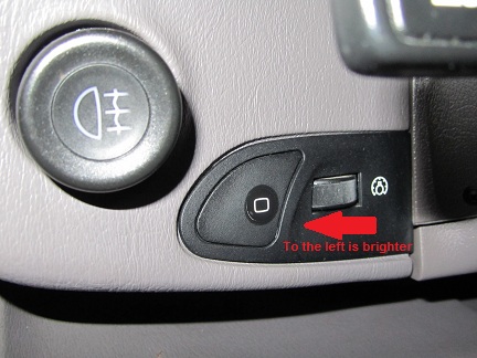
Firstly as I promised to you per PM, I just came back home and tried it out on my 1994 GTS and lost the bet with myself = I remembered wrong! To increase the illumination level on my car (and from all the maintenance records paper work that I do have from my car, the rheostat appears to be original as it has never been changed), I need to move my thumb to the left:
Any other Rennlister with a GTS out there who can confirm the same findings as me?
Secondly, about your RoHS question: as far as I know that is not checked @ customs in Europe for these kind of project type of shipments.
Ed: your PCB's already look great as per your earlier post #72
, and I hope that by now you have received the ones with both sides silkscreened.Firstly as I promised to you per PM, I just came back home and tried it out on my 1994 GTS and lost the bet with myself = I remembered wrong! To increase the illumination level on my car (and from all the maintenance records paper work that I do have from my car, the rheostat appears to be original as it has never been changed), I need to move my thumb to the left:
Any other Rennlister with a GTS out there who can confirm the same findings as me?
Secondly, about your RoHS question: as far as I know that is not checked @ customs in Europe for these kind of project type of shipments.
Last edited by Arnoud; 12-18-2012 at 01:17 PM. Reason: Typo
12-18-2012, 01:28 PM
#90
Addict
Rennlist Member
Rennlist Member
Thread Starter
I guess I'll need to study the way mine is mounted again and see if I can figure this out. I need to get into mine again anyway so I can get some more photos for the installation instructions.
Thanks, ammonman and Armoud for the information you provided.
OK, I won't obsess about it, but the first batch will probably be about 99% RoHS.