

New oil control solution for Race/ORR/SC/Stroker/GTS/GT/CS/SE/S4/S3 928 Engines
 05-07-2011 | 09:01 PM
#121
Addict
Rennlist Member
Rennlist Member
Joined: Oct 2003
Posts: 16,584
Likes: 1,697
From: Gone. On the Open Road
I've just now had the time to go through this whole thread.
First:
That's damn funny.
I agree with with DrBob: don't run folks off.
I think if Kevin and Greg ever had the time to get together in the same room with some tools, engines, and maybe a beer or two that they'd see that they are pretty-much talking about the same things just with some slightly different definitions.
Last, for Greg Brown:
The location of the Provent kinda makes it hard for the Forced Induction Folks that use the washer tank as the fluid sump for the heat exchangers. (And for folks that live in places where washer fluid is a necessity.) Dave Robert's vent kit puts the Provent in front, near (on the TS kit, attached to for NA) the front engine lift loop. For folks that don't have issues with the Provent sitting in plain sight, would there be any challenges in the re-plumbing?
05-07-2011 | 10:01 PM
#122

Former Vendor
Joined: Feb 2005
Posts: 15,230
Likes: 2,478
From: Anaheim
I've just now had the time to go through this whole thread.
First:
That's damn funny.
I agree with with DrBob: don't run folks off.
I think if Kevin and Greg ever had the time to get together in the same room with some tools, engines, and maybe a beer or two that they'd see that they are pretty-much talking about the same things just with some slightly different definitions.
Kevin and I communicate much better than we did originally. I've tried hard here to keep things on topic, specific, and simple. We both have our own views of things, of course. Kevin can sometimes lose me and if I need him to be more specific, I ask.
Last, for Greg Brown:
The location of the Provent kinda makes it hard for the Forced Induction Folks that use the washer tank as the fluid sump for the heat exchangers. (And for folks that live in places where washer fluid is a necessity.) Dave Robert's vent kit puts the Provent in front, near (on the TS kit, attached to for NA) the front engine lift loop. For folks that don't have issues with the Provent sitting in plain sight, would there be any challenges in the re-plumbing?
I don't see any problem of putting it where DR did. I'd need to think about the plumbing, but initially I'd think all that would be required is....less hose. Perhaps I could get DR to make a "modified Provent" kit for my pumping system and he could handle that part of the kit/pieces. I certainly would not want to make any pieces that he could/should provide....Lord knows there is enough of that happening, in this small 928 world, already.
05-07-2011 | 10:11 PM
#123

Racer
Joined: Jul 2004
Posts: 409
Likes: 0
Not being combative...just making sure I'm reading what you say...you English majors can be so hard to follow, sometimes.
Are you saying that your "solution" for the 928 engine is your scraper and windage tray and this will eliminate all the oiling problems in the 928 engine?
Are you saying that your "solution" for the 928 engine is your scraper and windage tray and this will eliminate all the oiling problems in the 928 engine?
I pulled this down off my website some time ago. It was time to move on:
With regards to the fatal problem of oil aeration in the 928, the Ishihara-Johnson 928 windage control system allowed the Dutch Stallion team to run their wet-sumped 928 S4 engine at typical rpms of 6800 for the first half of the 43 hour 2006 season (not including practice) and 7200 for the second half with stable oil pressure. The subsequent season was run at 7200rpms. This usage was accompanied by a 10 degree Celsius drop in coolant temperature from the 2005 engine which had less power. This 2006 engine was NA and developed 420 rwhp. To the author's knowledge, safely running this sustained rpm level in the wetsump engine with respect to oil related rod failures is unprecedented in the history of this engine.
Prior to the installation of the windage control system when they attempted to run their engine at 6800 rpm it failed in two days.
Upon teardown of the engine at the close of the 2006 season no discernable damage had occurred in the engine. The engine failed about midway into the 2007 season due to a broken timing belt -- this was unrelated to oil supply in the bottom end.
To be very clear, the windage control system here does not and cannot correct the second problem of oil ejection. In some situations it may even make it worse. Many, many Porsche experts believed the issue of oil ejection was causally tied to rod bearing failure. They are distinct but associated issues.
Louie Ott, in a Rennlist post suggests a solution:
Rob van Kol has used Louie Ott's suggestion and added a baffle trap as well. The oil ejection rate for the Dutch Stallion Team car is now at .25 liters per 50 minutes racing. These suggestions really work.
Prior to the installation of the windage control system when they attempted to run their engine at 6800 rpm it failed in two days.
Upon teardown of the engine at the close of the 2006 season no discernable damage had occurred in the engine. The engine failed about midway into the 2007 season due to a broken timing belt -- this was unrelated to oil supply in the bottom end.
To be very clear, the windage control system here does not and cannot correct the second problem of oil ejection. In some situations it may even make it worse. Many, many Porsche experts believed the issue of oil ejection was causally tied to rod bearing failure. They are distinct but associated issues.
Louie Ott, in a Rennlist post suggests a solution:
The oil filler breather I made can be seen on my web site on this page.
http://www.performance928.com/cgi-b...ass_parent=1128
Scroll down to the bottom and there are a couple of pics. I have some basic drawings (no dimensions) which I could email if you want. The inside of the aluminum cap has the threaded part from the old cap. Turn down the outside of the old cap. Turn out inside of the new cap to fit outside of old cap. Epoxy old cap inside the new cap. A hole has to be bored in the old cap to fit over the swivel projection in the center of the new cap. The size of the copper pipe "street L" that goes into the center of the cap is 3/4" and is about the smallest size I'd consider using. If there is a way to use 1" size, use that. It might fit. This was just an experimental thing and it worked out ok. You need to vent a large volume of blowby, but don't want high velocity which would carry oil with it. That's why the largest diameter you can use is best. I don't know what others have made. One key thing is to have the inlet on the underside of the cap project down into the filler so any oil that is on the surface has a hard time turning the corner and going up and out the breather.
Mark Kibort is in a class of his own out there somewhere. I learned a lot by thinking about Mark's cars and driving and accepting them as valid data. The German team in the early-mid 1990s came close to the sustained high rpms accomplishment but their engine had a bearing failure near the end of the season.
05-08-2011 | 04:08 AM
#125
Addict
Rennlist Member
Rennlist Member
Joined: Nov 2003
Posts: 2,608
Likes: 11
From: Sydney AUS
I've just now had the time to go through this whole thread.
First:
I think if Kevin and Greg ever had the time to get together in the same room with some tools, engines, and maybe a beer or two that they'd see that they are pretty-much talking about the same things just with some slightly different definitions.
?
First:
I think if Kevin and Greg ever had the time to get together in the same room with some tools, engines, and maybe a beer or two that they'd see that they are pretty-much talking about the same things just with some slightly different definitions.
?
05-08-2011 | 05:01 AM
#126
Former Vendor
Joined: Feb 2005
Posts: 15,230
Likes: 2,478
From: Anaheim
Kevin thinks all the bearings issues can be solved with his windage tray/scraper.
I've only got one thing to say....
Please, please Carl...please run your engine at Bonneville with just this modification to prove him correct....just make sure you are the only driver...please! I saw a picture of your son in a driver's suit....and that really scared me! Watch the shiny spinning coin, closely. Watch the spinning coin. You are getting sleepy. You should be the only driver. You should be the only driver. You are getting sleepy. You should be the only driver.
05-08-2011 | 07:27 AM
#127
Racer
Joined: Jul 2004
Posts: 409
Likes: 0
Sorry, I should clarify. There will be some performance level for a tracked vehicle at which point it will be neccessary to move to a dry sump simply because of the acceleration forces involved and the angle of repose of oil in such situations.
This is old stuff from the 1960s at the latest but people forget. Read Dave Bean's comments about wetsump pans in English Ford motors and think about dry sumps used in Formula Ford since that time, much less higher levels of racing.
Aside: There are quite a number of people using wetsumped aircraft engines; this does not mean there is no need, requirement rather, for dry sumped engines at higher performance levels. If you have time and interest there are a large number of declassified NACA papers and some cover this area. A lot of people gave their lives in determining the need for various technologies discussed there.
05-08-2011 | 11:01 AM
#128
Addict
Rennlist Member
Rennlist Member
Joined: Jun 2003
Posts: 9,384
Likes: 63
From: Helsinki, Finland
Are you saying this is deep sump? If yes, I dissagree. It has smaller cut for AC belt in right front corner than later parts. This does not mean its one mm deeper than any one of the later sump styles made.
05-08-2011 | 11:53 AM
#129
Addict
Rennlist Member
Rennlist Member
Joined: Oct 2003
Posts: 16,584
Likes: 1,697
From: Gone. On the Open Road
As for the rest, I'm not Yenta (... matchmaker, matchmaker, bring me a match ...) I tried, but I'm done.
 05-08-2011 | 01:44 PM
#130
Racer
Joined: Jul 2004
Posts: 409
Likes: 0
Yes, I remember you mentioning this before. I agree that the cut for the AC belt is deeper. This is a convenient and more obvious visual cue to quickly identifying the piece.
Now slide your attention across that ribbed area of the casting to the portion where the oil return pipe is plumbed in. Notice that the ribs in that brief section do not rise to meet the level of the ribs on either side? On later pans -- I have one plopped in front of my keyboard -- the ribs are even across this area. I think this is 20mm but this is not why I suggest the deeper sump in the first place. Twenty millimeters is the value I obtained by examining the technical drawing.
The casting IS a complex piece.
If you actually have one of these early castings could you please measure it?
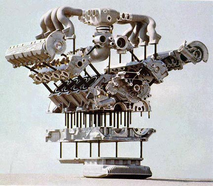
I am glad you brought it up again because in looking at page 45 of Brian's book there is a shot of Alfred Waibel inspecting an early batch of the engines. This engine appears to match the one in the museum. Closer inspection of the 1977 factory pictures suggests there might have been yet another intermediary design.
Edit: Samantha walked by the office here and saw the big oily 928 pan on the desk. "You're not doing that again? That consumes days of your time !"
Yup. It did and does. I do have actual work to get done.
Last edited by Kevin Johnson; 05-08-2011 at 01:51 PM. Reason: Busted
05-08-2011 | 05:17 PM
#131
Addict
Rennlist Member
Rennlist Member
Joined: Jun 2003
Posts: 9,384
Likes: 63
From: Helsinki, Finland
Cut in that picture is smaller than later setup. Smaller, not larger. Depth of the cut is about same as in later pans but angle is different. This does not say anything about height of the entire pan.
Around 1900 early '78 MY pans have threaded oil pipe. This means pan design in that area is different than later setups which use bolts to hold oil pipe in place. This does not say anything about height of the entire pan. I'll repeat, this does not say anything about height of the entire pan.
I bet 928intl and others have many of these early engines around and can easily check pan height. I'm willing to bet they would have noticed 20mm height difference years ago already if such difference existed. 818 1659 for 5sp and 818 9281 for automatics were last engine numbers to use threaded oil pipe. One other obvious clue that these and later pans are same height is that oil level dipstick and its guide tube are same part for both threaded and later setups. Guide tube was used even in early 32V engines. 20mm more or less oil in pan would mean several litres difference.
Which you are clearly reading wrong.
I know at least three very early cars with original engines but do not have access to measure the right now.
Threaded oil pipe design shown in it was used up to engine numbers mentioned above.
Now slide your attention across that ribbed area of the casting to the portion where the oil return pipe is plumbed in. Notice that the ribs in that brief section do not rise to meet the level of the ribs on either side? On later pans -- I have one plopped in front of my keyboard -- the ribs are even across this area. I think this is 20mm but this is not why I suggest the deeper sump in the first place.
I bet 928intl and others have many of these early engines around and can easily check pan height. I'm willing to bet they would have noticed 20mm height difference years ago already if such difference existed. 818 1659 for 5sp and 818 9281 for automatics were last engine numbers to use threaded oil pipe. One other obvious clue that these and later pans are same height is that oil level dipstick and its guide tube are same part for both threaded and later setups. Guide tube was used even in early 32V engines. 20mm more or less oil in pan would mean several litres difference.
Twenty millimeters is the value I obtained by examining the technical drawing.
If you actually have one of these early castings could you please measure it?
I am glad you brought it up again because in looking at page 45 of Brian's book there is a shot of Alfred Waibel inspecting an early batch of the engines. This engine appears to match the one in the museum.
05-08-2011 | 07:22 PM
#132
Racer
Joined: Jul 2004
Posts: 409
Likes: 0
Around 1900 early '78 MY pans have threaded oil pipe. This means pan design in that area is different than later setups which use bolts to hold oil pipe in place. This does not say anything about height of the entire pan. I'll repeat, this does not say anything about height of the entire pan.
I bet 928intl and others have many of these early engines around and can easily check pan height. I'm willing to bet they would have noticed 20mm height difference years ago already if such difference existed. 818 1659 for 5sp and 818 9281 for automatics were last engine numbers to use threaded oil pipe. One other obvious clue that these and later pans are same height is that oil level dipstick and its guide tube are same part for both threaded and later setups. ...
Maybe you can identify which engines/years they belong to.
05-08-2011 | 08:05 PM
#133
Racer
Joined: Jul 2004
Posts: 409
Likes: 0
Continued...
Steadily working here. I believe that I have identified yet a fourth sump variant -- pre-production. See page 72 of Project 928. I do love data.
Edit: There is really a great shot of this early sump on page 132.
Edit 2: I apologize, that is actually a fifth variant.
This is the first time I have looked through Project 928. Some other observations from the pictures therein: Porsche did indeed preceed Ford in the crankcase vent flow investigations outlined in the Modular engine (then Coyote). The oil pump was progressively driven faster and faster (and perhaps made larger and larger). The bedplate was given modifications to improve flow, however the rigidity of the bottom end appeared to be a problem. The engineering for rigidity took precedence over considerations for flow thereby compounding the oiling problem. The complex bedplate passage engineering was likely a result of the oil pump being driven faster and faster. The taller bedplate in the technical drawing would offer more rigidity. The shorter bedplate would exacerbate the windage issue. The need to make the sump more shallow would exacerbate the windage and oiling issue. And on and on.
A highly complex problem that clearly had been under investigation for at least four years prior to the launch in 1977. Interesting how no written mention whatsoever is made of this. Anyway, multiple engineering theses could be written here. (Edit 3. The V6 thesis -- !! )
)
Steadily working here. I believe that I have identified yet a fourth sump variant -- pre-production. See page 72 of Project 928. I do love data.
Edit: There is really a great shot of this early sump on page 132.
Edit 2: I apologize, that is actually a fifth variant.
This is the first time I have looked through Project 928. Some other observations from the pictures therein: Porsche did indeed preceed Ford in the crankcase vent flow investigations outlined in the Modular engine (then Coyote). The oil pump was progressively driven faster and faster (and perhaps made larger and larger). The bedplate was given modifications to improve flow, however the rigidity of the bottom end appeared to be a problem. The engineering for rigidity took precedence over considerations for flow thereby compounding the oiling problem. The complex bedplate passage engineering was likely a result of the oil pump being driven faster and faster. The taller bedplate in the technical drawing would offer more rigidity. The shorter bedplate would exacerbate the windage issue. The need to make the sump more shallow would exacerbate the windage and oiling issue. And on and on.
A highly complex problem that clearly had been under investigation for at least four years prior to the launch in 1977. Interesting how no written mention whatsoever is made of this. Anyway, multiple engineering theses could be written here. (Edit 3. The V6 thesis -- !!
)
Last edited by Kevin Johnson; 05-08-2011 at 11:12 PM.
05-08-2011 | 08:26 PM
#134
Thread Starter
Archive Gatekeeper
Rennlist Member
Rennlist Member
Joined: Sep 2002
Posts: 17,674
Likes: 2,842
From: Irvine, CA
Mark has got dozens of engines on the wall, sorted by year. I promised to go get measurements last time this came up, but didn't. Will get up there when I can to settle this.
05-08-2011 | 08:27 PM
#135
Racer
Joined: Jul 2004
Posts: 409
Likes: 0
Erkka,
I know you think I mismeasured the drawing. I have a link here to a file (large) where I have superimposed some reference lines.
http://www.crank-scrapers.com/PORSCHE%20928.jpg
The sump reservoir depth at the pickup opening floor depression is ~ 137mm versus ~117mm in the early block. The bedplate thickness is ~ 90mm versus 80mm in the early block.
The scaling can be established by the cross-section appearing to be at the third main in the bedplate. The spacing of the bedplate with respect to the longitudinal axis of the crank appears to match that of the early engine.
The cross-section slice of the oil-pan-sump-area is forward of this position and appears to be transecting the pickup and the sump.
~~~~
Please let me know where my measurements are wrong. Thanks.