

MaxJax arrived today
 04-13-2011, 07:55 PM
#16
Chronic Tool Dropper
Lifetime Rennlist
Member
Lifetime Rennlist
Member

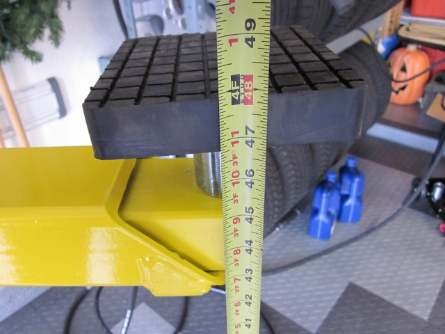
Not really. The 928 suspension hangs with the bottom of the tires at 36" off the floor, lift pads at 48" off the floor. No telling how much your intended upper/stored car would hang down, but it's unlikely the 928 ill fit. On the MaxJax thread, I shared some more measurements made when the car was up; those might be helpful.
 04-13-2011, 10:44 PM
#17
Pro

Join Date: Mar 2004
Location: Perth, Western Australia
Posts: 715
Likes: 0
Received 14 Likes
on
13 Posts

Why do you think Oprah was so excited to do a show in the Sydney Opera House? She hasn't been that light since high school!
Actually, no, we didn't lift it, but we did slide it across the truck floor to the tail-lift.
 04-17-2011, 09:11 PM
#18
Rennlist Member
Thread Starter

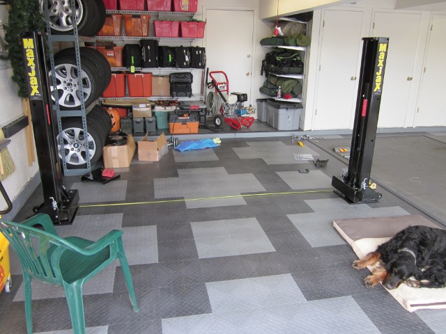
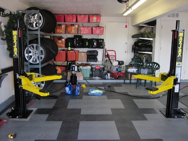
I had some time today so did a little more on the lift install prep. Started by fully disassembling the shipping skid and doing a rough placement of the columns:
Used a floor jack to support the columns/rams while removing skid frame
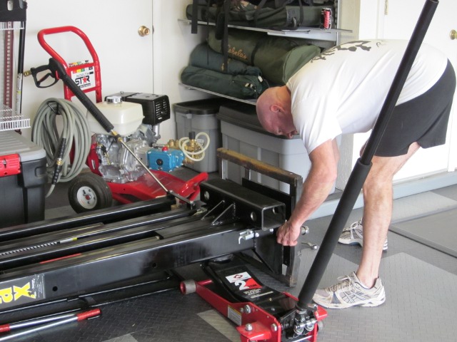
Columns detached from skid and ready to stand up
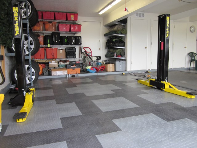
Upright and ready to assemble wheels
Columns roughly in place. This spacing is 128" (outside edge-outside edge) and is dictated by overhead conflicts with the fully extended rams. Notice my hired help in the right foreground - and to think I'm paying room and board!")
Used a floor jack to support the columns/rams while removing skid frame
Columns detached from skid and ready to stand up
Upright and ready to assemble wheels
Columns roughly in place. This spacing is 128" (outside edge-outside edge) and is dictated by overhead conflicts with the fully extended rams. Notice my hired help in the right foreground - and to think I'm paying room and board!
04-17-2011, 09:20 PM
#19
Rennlist Member
Thread Starter
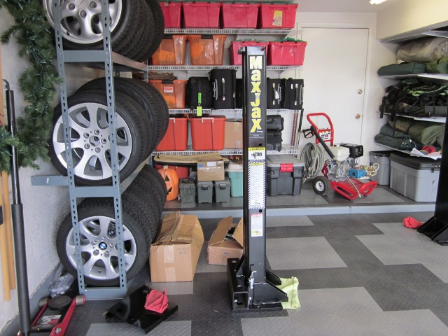
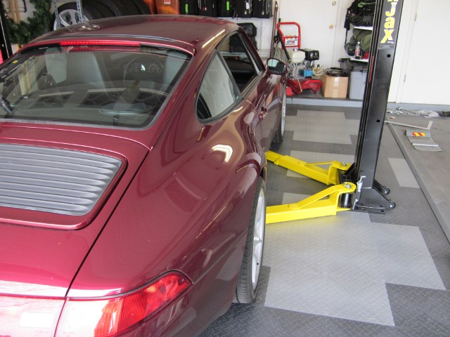
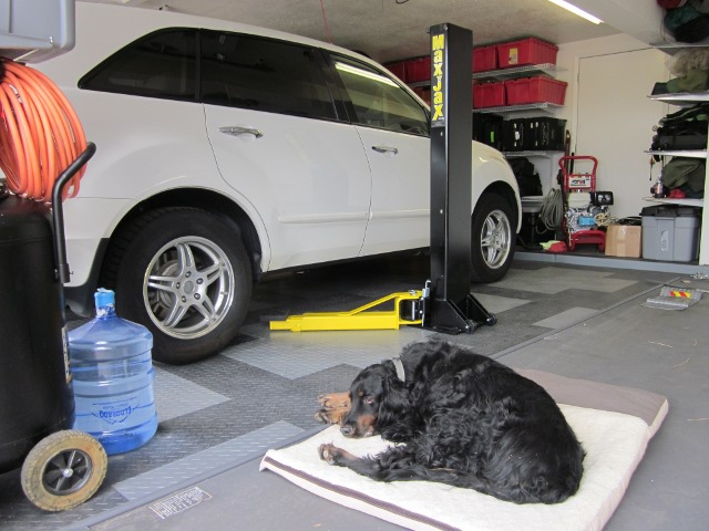
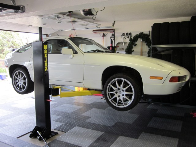
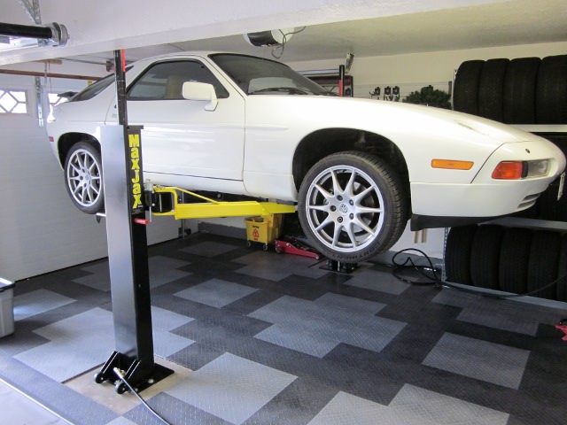
Continued by checking lift arm/pad fit with the cars I want to work with:
Lift arms/pads on free standing columns ready to check fit
The Sauce fits
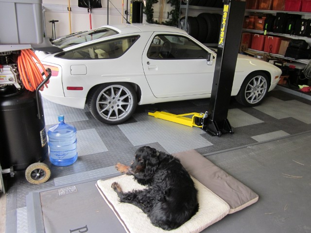
As does the Pasta
The AcuraSaurus also fits; fortunately all I need to do is swap wheels twice a year - it's too tall for this lift/garage combo
Lift arms/pads on free standing columns ready to check fit
The Sauce fits
As does the Pasta
The AcuraSaurus also fits; fortunately all I need to do is swap wheels twice a year - it's too tall for this lift/garage combo
04-17-2011, 09:32 PM
#20
Rennlist Member
Thread Starter
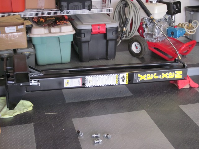
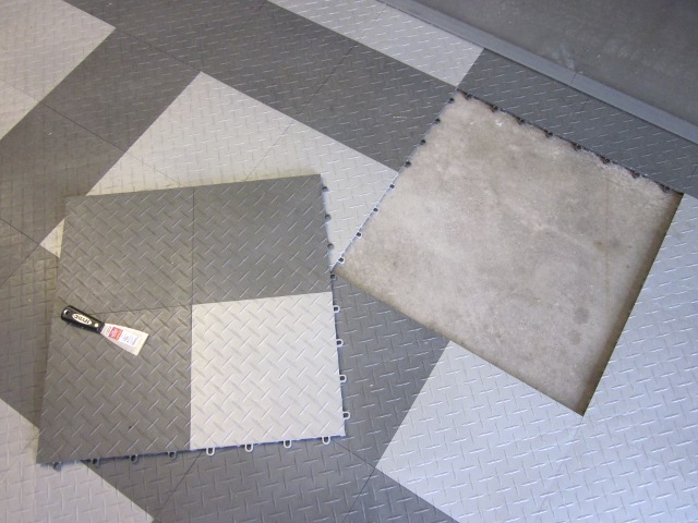
Closed out the day (it was beer-thirty anyway) by prepping the floor tiles under the columns for easy removal/replacement:
Lifted the 4 adjacent tiles under each column with a stiff putty knife. It helps if you know which way the loops and tabs run. It worked best for me to insert the putty knife directly on top of a loop and pry so that the tab inside the loop pops out and the tile with the tab then lifts up
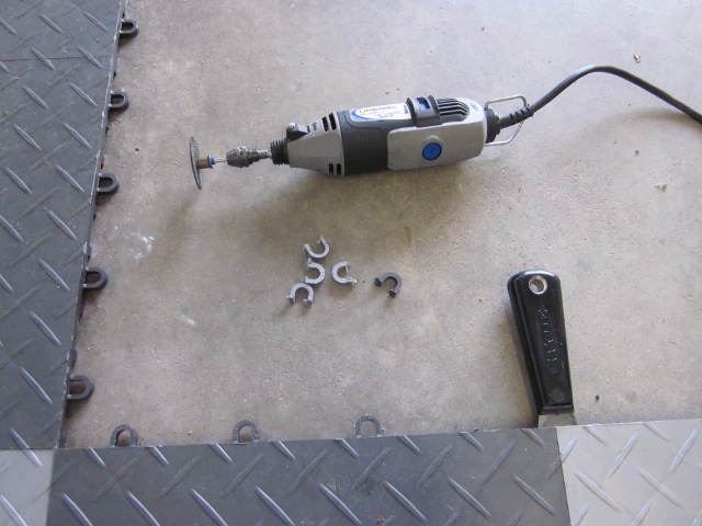
Removed the loops form the lifted section using a dremel with a plastic blade
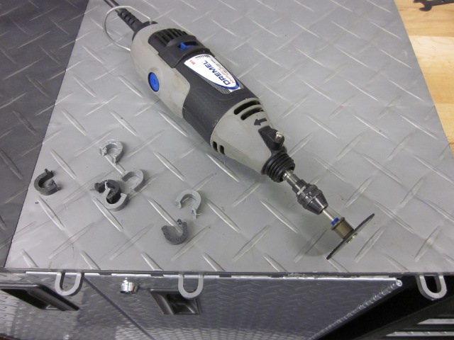
Also removed the tabs from the lifted section to ease removal/re-install
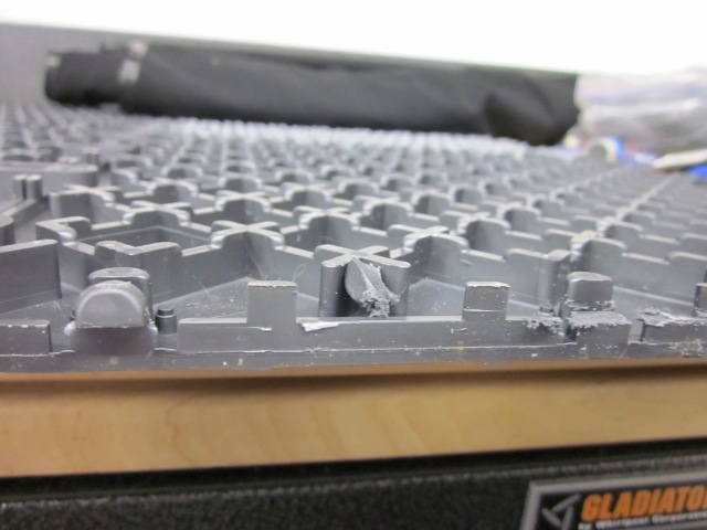
Removed the tabs from the adjacent tiles on the floor. Used the putty knife to hold the tile up away from the concrete while I was cutting with the dremel. The liftable sections are now very easy to take out and put back
Lifted the 4 adjacent tiles under each column with a stiff putty knife. It helps if you know which way the loops and tabs run. It worked best for me to insert the putty knife directly on top of a loop and pry so that the tab inside the loop pops out and the tile with the tab then lifts up
Removed the loops form the lifted section using a dremel with a plastic blade
Also removed the tabs from the lifted section to ease removal/re-install
Removed the tabs from the adjacent tiles on the floor. Used the putty knife to hold the tile up away from the concrete while I was cutting with the dremel. The liftable sections are now very easy to take out and put back
 Bastard.
05-05-2011, 11:26 PM
Bastard.
05-05-2011, 11:26 PM
#22
Rennlist Member
Thread Starter
 05-05-2011, 11:44 PM
#23
Rennlist Member
Thread Starter
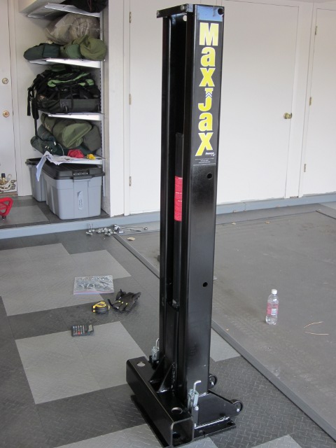
I mounted the posts before I did the rest of the assembly - figured that would be the hardest part:
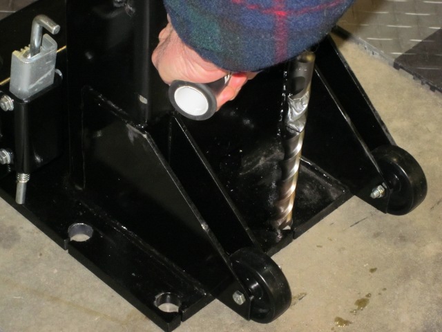
Per the instructions started with the rear center hole, and ran a shop vac while drilling to pick up the dust and debris
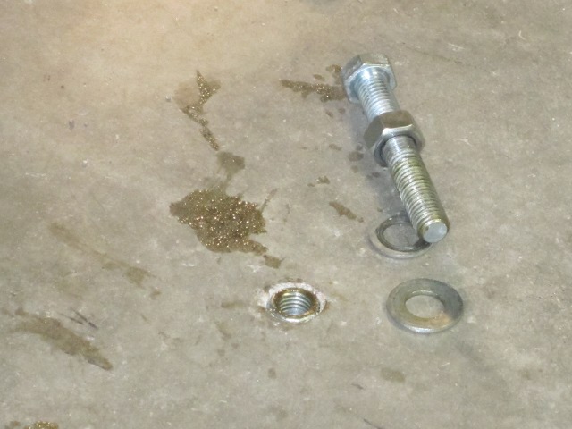
After blowing out the hole with compressed air and re-vacuuming, assembled the anchor seating bolt/nut washers, drove the anchor into the hole with a small sledge, and used a wrench on the nut (turned) and a socket on the bolt (held still) to set the anchor. The instructions said three turns - five or so seemed to work better for me
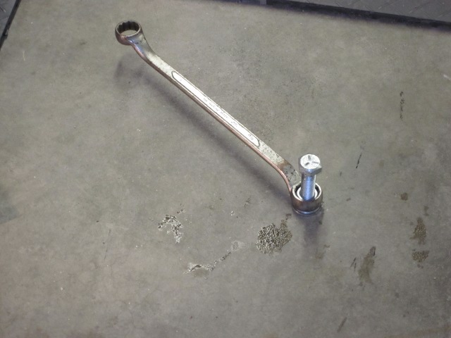
The set anchor was still below the surface but snug none the less. Note the grease on the anchor set bolt - tip provided by DrBob
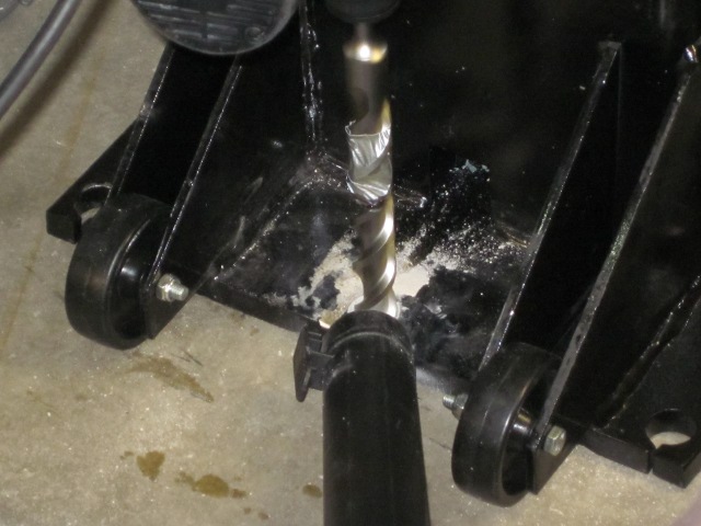
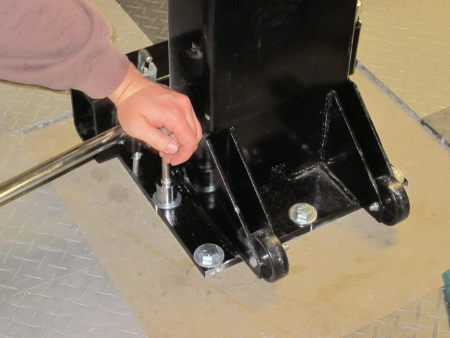
Reset the lift column, bolted it in place with the first anchor, and drilled the remainder of the holes. I have a confession to make: used an expendable center punch to pop the concrete in the hole center and immediately drilled with a 7/8" bit, bypassing the instructions to drill a pilot with a 5/8" bit first. The guy at Home Depot (rotary hammer/bit rental) suggested this approach and it worked out well. Repeated the pop/drill/clean/anchor set for all remaining holes
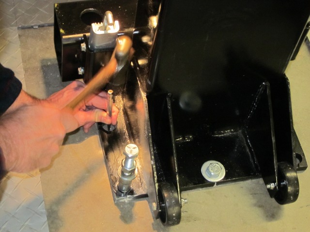
Per the instructions started with the rear center hole, and ran a shop vac while drilling to pick up the dust and debris
After blowing out the hole with compressed air and re-vacuuming, assembled the anchor seating bolt/nut washers, drove the anchor into the hole with a small sledge, and used a wrench on the nut (turned) and a socket on the bolt (held still) to set the anchor. The instructions said three turns - five or so seemed to work better for me
The set anchor was still below the surface but snug none the less. Note the grease on the anchor set bolt - tip provided by DrBob
Reset the lift column, bolted it in place with the first anchor, and drilled the remainder of the holes. I have a confession to make: used an expendable center punch to pop the concrete in the hole center and immediately drilled with a 7/8" bit, bypassing the instructions to drill a pilot with a 5/8" bit first. The guy at Home Depot (rotary hammer/bit rental) suggested this approach and it worked out well. Repeated the pop/drill/clean/anchor set for all remaining holes
05-05-2011, 11:56 PM
#24
Rennlist Member
Thread Starter
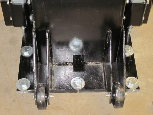
All of the anchors set, and all are still below the surface. Note that the hole edges were almost perfect immediately after drilling, but the edges chipped when driving the anchors into the holes
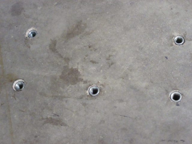
Replaced the lift column and torqued the bolts to 90ft/lbs. Per DrBob's tip I'll use 50ft/lbs for subsequent set up - just wanted to make sure the anchors were fully set. Only one of the 10 total anchors (both columns) raised while doing this, and it is just at the surface, so all appears OK
The column installed and torqued down
05-06-2011, 12:16 AM
#25
Rennlist Member
Thread Starter
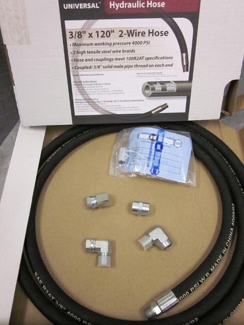
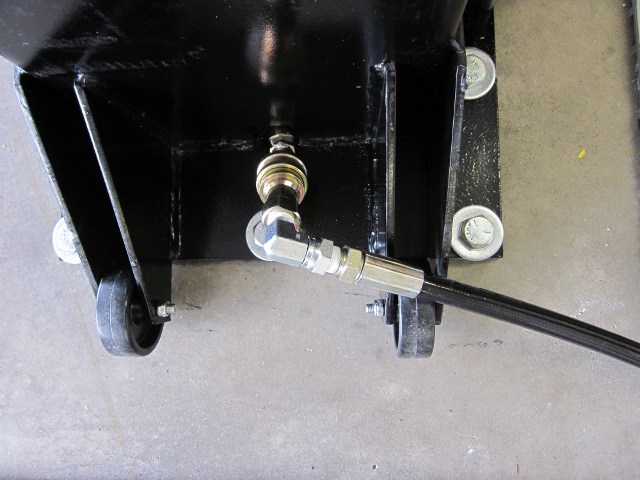
Received the "extra" parts to add length to the hoses. I went ahead and got two 10' hoses with couplers figuring that would give me enough flexibility in portable pump placement. I also ordered some 90 degree elbows to help the hose lay flatter on the floor and reduce the chance of tripping
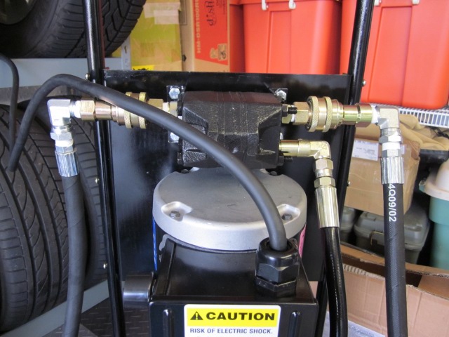
The pump assembly had a small wrinkle - the pump body outlet (red plug) is on the opposite side from where the instructions state and flow divider required
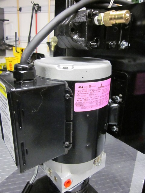
Fortunately the fix was easy - per Danmar tech support, on the flow divider swapped the right hand side inlet plug with the left hand side inlet elbow, resulting in the elbow/hose now being on the needed side. We'll see if it all works out and the circuit breaker holds
The pump assembly had a small wrinkle - the pump body outlet (red plug) is on the opposite side from where the instructions state and flow divider required
Fortunately the fix was easy - per Danmar tech support, on the flow divider swapped the right hand side inlet plug with the left hand side inlet elbow, resulting in the elbow/hose now being on the needed side. We'll see if it all works out and the circuit breaker holds
05-08-2011, 11:14 PM
#26
Rennlist Member
Thread Starter
Finally! Finished the install and used it on the first job (swapped the Mama's winter wheels/tires for summers). Here are the last few shots:
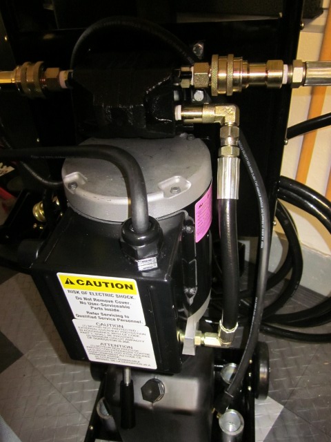
The elbows and extra hose really do help. The hose lays flatter at the posts and off of the flow divider on the pump cart. No leaks at all by following DrBob's tips (earlier in this thread)
I did have a couple of issues. I managed to push the pump reservoir seal into the reservoir during the initial fill (putting the "cap" back on), so I need to contact Danmar for a replacement. Also, the reservoir is supposed to be ~7 quarts capacity, but mine is full at 6. Good thing it's not any smaller as all 6 are needed with the extra 20' of hose I added - none to spare .
.
Bleeding went per the instructions and both sides lift/lower evenly
I loose a little lift at the top lock point due to the floor tile height off of the concrete
The elbows and extra hose really do help. The hose lays flatter at the posts and off of the flow divider on the pump cart. No leaks at all by following DrBob's tips (earlier in this thread)
I did have a couple of issues. I managed to push the pump reservoir seal into the reservoir during the initial fill (putting the "cap" back on), so I need to contact Danmar for a replacement. Also, the reservoir is supposed to be ~7 quarts capacity, but mine is full at 6. Good thing it's not any smaller as all 6 are needed with the extra 20' of hose I added - none to spare
.Bleeding went per the instructions and both sides lift/lower evenly
I loose a little lift at the top lock point due to the floor tile height off of the concrete

 06-18-2011, 05:05 PM
#30
Three Wheelin'
First , thanks a lot Marty for the valuable informations you give me and thanks Dr bob for your input in this thread. I have a concern. After the installation of the lift I did lift my old BMW 325 a couple of times and after the Porsche. I had no problem at all. But....My first torque on the 10 bolts was 50 ft-pounds. After the lifting all the bolts were loose. I had to re torque everyone of them up to a turn and 3/4 on most of them. But was able to get 50 ft/pounds again... Was it normal to found the bolts so loose....