
Still trying to find out a cheap way to give 13" rotors to the '84's
 01-06-2011, 03:27 PM
#181
Rennlist Member
Thread Starter
that is not a centering diameter of 85mm, as nothing touches or is near this opening. its just a window for the bearing cap.
the ID is porsche, because the roots of this rotor are porsche. 157.1mm the S4 and I believe the earlier cars use this centering diameter on the ID.
the setscrew is not a big deal, unless you want to carve one out on the 928 hub face. better to just drill a hole in the rotor that matchs the stock 928 set screw and use it. its not needed other than for convienience.
mk
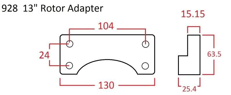
Found an interesting technical drawing of the 330mm Dia. Cayenne rotor.....
85mm centering diameter, but only 1 setscrew still at 130mm PCD ( 136 PCD = 944/968) and 157mm I.D. hub interface. I would think that the Cayenne hub has an 85mm centering interface.
The 85 928 hub I have on hand matches the 155mm O.D. 944/968 Hub that I have also. Something tells me the Later 928 hubs went to 157mm O.D. or they only rely on the set screws for centering the rotor. Can anyone confirm? I cannot find technical drawings for the various years of the 928 rotors
 01-06-2011, 04:09 PM
#182
Until I get a later 928 hub in hand and a true tech drawing of the early & later 928 rotors, I am a little suspect. The tech drawings for the early and late 944 rotors have a 155mm hub interface. Centering such a large 330mm rotor would be critical for high speed balance.
01-07-2011, 01:53 PM
#183
Rennlist Member
Thread Starter
the good news is that the 330mm rotors have the same ID spec. Im not sure about the 79 and 84 cars, but that should be easy to check. if its only the alignment, just drilling a simple hole in the rotor hat that matches the hub set screw is an EASY fix or assurance of good balance of the rotor when spinning.
might have a sample of the adaper plate this weekend or early next week. then, a test with the actual '82 car set up and see how much caliper griding we will need to do. I suspect that will be the easy part.
mk
might have a sample of the adaper plate this weekend or early next week. then, a test with the actual '82 car set up and see how much caliper griding we will need to do. I suspect that will be the easy part.
mk
Until I get a later 928 hub in hand and a true tech drawing of the early & later 928 rotors, I am a little suspect. The tech drawings for the early and late 944 rotors have a 155mm hub interface. Centering such a large 330mm rotor would be critical for high speed balance.
01-09-2011, 03:24 AM
#185
Rennlist Member
Thread Starter
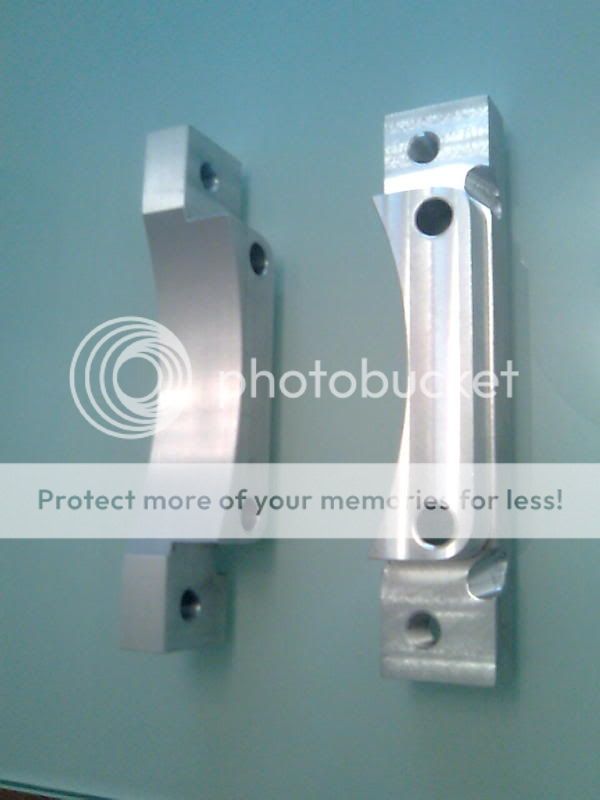
Here is the part i plan to use (test), made of wood. maybe if it proves itself, it will turn into 6061 like Pinocchio 
edited. Part was wrong . cut out area was on the thin side, should have been on the thick side.
edited. Part was wrong . cut out area was on the thin side, should have been on the thick side.
Last edited by mark kibort; 01-10-2011 at 06:22 PM.
01-09-2011, 09:58 AM
#186
Rennlist Member
Mark, to get your adapter plates spot on you could try this.
Make up two pieces in steel, one that bolts to the upright
and one that bolts to the brake calliper.
Bolt the adapter pieces to upright and to calliper then
move calliper into desired position on disc.
Get assistant to put brakes on then tack weld the pieces together.
You now have a "buck" with the bolt holes in the ideal relevant positions.
Use the dimensions of this buck to machine the actual adapter from steel.
Done this in the past and it works very well. It allows you to get the
pads/ calliper right on the edge of the disc maximising the swept area.
01-09-2011, 01:55 PM
#187
Rennlist Member

Actually woods great. Eeasy to manipulate, to find the ideal position, and then use as a template to make a functioning part.
I'm excited to see a larger rotor all mocked up to verify proof of concept.
 01-09-2011, 02:15 PM
#189
Rennlist Member
Thread Starter
what material should I use for the finished product? steel, alloy? let me kwow, or what I should NOT use too.
The bolt centers are 24mm apart, and the holes themselves are 12mm diameter, so that only leaves a half an inch of thickness between them. something to be concerned about?
Mk
The bolt centers are 24mm apart, and the holes themselves are 12mm diameter, so that only leaves a half an inch of thickness between them. something to be concerned about?
Mk
01-09-2011, 04:35 PM
#190
I've built many different brackets with 1/2" and less between bolt walls using 6061. The only unknown from the drawing/mock-up I have is the arch, but it goes thru the thickest part and the rest is plenty beefy. I designed an arched set of adapters for the RX7 brakes on the rears of these cars and it is mega strong thru the arch area. It wouldn't be a concern here either. I usually start with lexan or delrin for mock-ups, whatever is lying around....
01-09-2011, 05:02 PM
#191
Race Director
The good news is whatever part you need Sean can make real easy..... I would imagine if you got it scanned into the CAD program that he uses you could even email it to him!!!!
01-09-2011, 05:24 PM
#192
1" x 2.5" 6061-T6 is common stock and not that expensive. I would CNC the arc in the brackets to get maximun strength. Don't forget that the bracket/mounting holes are subjected to axial forces and not being pulled radially (outwards).... This diagram keeps 1/2" billet around the mounting holes at all points at 1/2" thick too....
Last edited by xschop; 01-09-2011 at 08:44 PM.
01-09-2011, 05:48 PM
#193
If you need to you can clearance the spindle ears at the bracket edge with a 1" end mill just in that area.
Also as a side note, I would put my money on 1/2" billet over the 7.25mm of cast iron 928 spindle ear in a stress test.
Also as a side note, I would put my money on 1/2" billet over the 7.25mm of cast iron 928 spindle ear in a stress test.
01-10-2011, 07:32 PM
#194
Rennlist Member
Thread Starter
I got to scots house and started to play around with the rotors and wood mock up of the adapter. I cut out the wrong side (should have been the thick side) but then that was fine as i was trying to find out what the clearance issues were going to be.
looks like a pretty straight forward fit.
Notice the clearance to the lower ball joint. sure looks like there is room for S4 rotors,but looks can be decieving.
Looks like its a breeze to file down the edges of the caliper. it will be only a couple of mm's or so and the piece of that bridge is solid cast iron.
Last edited by mark kibort; 01-10-2011 at 08:09 PM.