Still trying to find out a cheap way to give 13" rotors to the '84's
 01-03-2011, 03:19 PM
#166
At that thickness, use 4130 bar/flat. The diagram I posted you could use 6061 alloy and the spindle to adapter thickness should be at least 5/8"
Last edited by xschop; 01-03-2011 at 06:33 PM.
 01-03-2011, 04:40 PM
#167
Rennlist Member
Thread Starter
now, is the spindle mounts tapped?? i think that they are.
your diagram has the bolts coming to the adapter from the inside, and i dont think there is room to turn a bolt head to tigthen or remove.
IF the spindle is tapped, then my idea might work
just flat bar stock, 9mm thick (half the thickness recommended for 6061)
and a through hole on the mounting to the spindle mounts and tapped hole to mimic the spindle holes where the calipers mount to the outside of them.
the only change to the diagram is to carve out an arc to make room for the caliper piston housing, so I added the blue area that would be removed.
thoughts?
01-03-2011, 04:47 PM
#168
Rennlist Member
Thread Starter
But, I think the caliper is the tapped part, so that would change my idea quite a bit. I would then need to make something more elaborate like this:
it would mount to the outer car side of the spindle mounts, and the have to extend inward and the outward by the 24mm we need. more complex of a mount , but doeable, right?
I mocked up something I could look at and understand out of cardboard.
the spindle mounts would be in front of the bottom most hole you see (we would be looking at the inside of the rotor and mounting area. the caliper would mount to the upper hole as the bolt would go through the cardboard, and to the threaded holes on the caliper. this would push the caliper out the 9mm we need, but still allow for alll the components to bolt up the traditional way.
01-03-2011, 05:19 PM
#170
My diagram is correct on page 6 but shows the side view of the bracket and yes there will need a curvature inset for the factory sliding caliper body and the 928 caliper is tapped M12 x 1.5 and the spindle is bored/drilled 12.06mm. Even with the rotor mounted, there is room to put the bolts thru the spindle (towards engine) into the M12 x 1.5 tapped adapter and tighten. Then you bolt the caliper thru the adapter (bolts facing away fr. engine) and tighten.
FYI, The factory caliper bolts are M12 x 1.5 x 50
This camera pic I took at the shop the other day shows the caliper tapped. The spindle dims I posted at the ears can be used to figure the adapter thickness dimensions
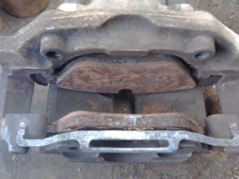
FYI, The factory caliper bolts are M12 x 1.5 x 50
This camera pic I took at the shop the other day shows the caliper tapped. The spindle dims I posted at the ears can be used to figure the adapter thickness dimensions
01-03-2011, 05:35 PM
#171
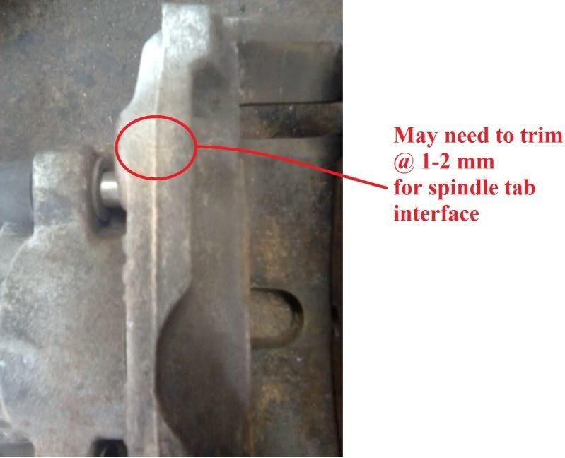
I see what you are talking about now. On my 85 spindle the front and back of the spindle mounts are machined/fly-cut parrallel and nice and flat for the factory hex head bolt base. I mic'd to confirm. that's why I drew the adapter bracket the way I did to keep it one piece and simple to machine.... HTH
So if you use billet stock to mill a bracket, the bracket thickness at the caliper will be 15.875mm (5/8") + 19.25mm - 9mm = 26.125mm
26.125 - 0.725 = 25.4mm (1.00" billet bar stock- adapter thickness at caliper requires less machining)
15.875 - 0.725 = 15.15mm (adapter thickness at spindle)
330mm rotor - 282mm rotor O.D. = 24mm (Z dim)
(These calcs go off mic'd spindle ear thicknesses of 19.25mm)
Last edited by xschop; 01-03-2011 at 07:07 PM.
01-03-2011, 06:48 PM
#172
Rennlist Member
Thread Starter
I see. much simpler. Plus the 'wrench" getting in there is a mute point, because once you mount the adapter, you never have to touch it again. you only need to loosen and tigten the new bolts attaching the calipers that are mounted further outer in radius.
so, its a flat block with a step leaving 15.15mm of material left. that way, you get the 9mm offset. AND, all you need to do is carve out that arc to clear the caliper piston body. smart! I just didnt know if you wanted to mount to the inside of the spindle arm. i guess if it has a flat surface, why not.
so, the inner holes will be tapped M12x 1.5pitch and then the outer holes are open and drilled to a through hole of 12.06mm
Now, you have one error in your drawing, the radius change is only 24mm,NOT 48mm. easy oversight. the entire diameter difference is 48mm, but the raduis is only 24mm.
that looks like the design to go with.
Mk
01-03-2011, 07:04 PM
#173
Yes, I caught myself after I was trying to get the dims posted for you. It takes awhile for Photobucket to replace the image so 24mm is correct, but if you don't want to grind on the caliper body or spindle ears 25.5mm is on the money but you'll have some overhang of the pad. I say get out the grinder since you'll be doing it to the caliper bridges anyways.
Also this design puts the caliper radius cutout thru the thick part of the adapter and hella strong.
The only thing I should add is that other spindles should be checked for that 19.25 dim on the spindle ear thickness to confirm and that the backside surface where the factory hex-head bolt seats is indeed flat/parallel to the opposite side where the caliper originally mounted.
01-05-2011, 11:17 PM
#176
Has anyone tried the Cayenne 330mm rotor on the 928 hub yet? If so, does it have 2 set screws like the 944,928 and what is their PCD? Reason why is I want to machine the billet hubs for them. They'll be getting the 944/968 dims and the BoxsterS dims so centering rings are not needed.
01-05-2011, 11:35 PM
#177
I have been preoccupied, I can almost guarantee it will be different, the rears are different that I can say. Will you have two options with the hubs as I will just want a standard hub as I will make the hats, in saying that, if the Cayenne is the new deal, i.e Porsche standard I may be able to buy hats for my app although I doubt that.
Greg
Greg
01-05-2011, 11:45 PM
#178
I will make the first set 100% identical to the 85 928 dims, the only thing extra I will do to them besides beef them at the bases and bearing channels is to machine set screw dims for all the 9-series rotors. And if the 330mm Cay. rotors fit the 155mm O.D. of the 928 hub and sit flush, I will machine their set screw PCD's as well.
I will report back the Wilwood hat info when I get a chance. There is a series that can be machined for the 71.6mm hubcentric at different offsets. They were like $90 ea IIRC.
As a side note, I chatted with Hacker about custom offsets for ideal wheels. I can make the Early 79-85 hubs 0-16mm offset and not affect the structure near the outter bearing seat.
Last edited by xschop; 01-06-2011 at 12:14 AM.
01-06-2011, 01:59 PM
#179
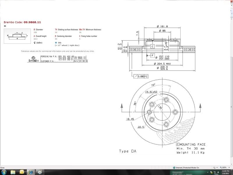
Found an interesting technical drawing of the 330mm Dia. Cayenne rotor.....
85mm centering diameter, but only 1 setscrew still at 130mm PCD ( 136 PCD = 944/968) and 157mm I.D. hub interface. I would think that the Cayenne hub has an 85mm centering interface.
The 85 928 hub I have on hand matches the 155mm O.D. 944/968 Hub that I have also. Something tells me the Later 928 hubs went to 157mm O.D. or they only rely on the set screws for centering the rotor. Can anyone confirm? I cannot find technical drawings for the various years of the 928 rotors
Last edited by xschop; 01-06-2011 at 02:26 PM.