
928 Stroker Crank Drawing or Model

 10-29-2010, 10:51 PM
#62
Former Sponsor

By Gargoyle28
Hi, I was conservative with the weight I quoted, however you may require some heavy metal to reach it. Also my crank has more modern technology, as such the big ends are smaller, in my case 48 mm (Honda) I could have used 47 mm (BMW) which is what the whole Nascar field runs.
Now as I have described the gains here before I will just say there is measurable gains, these come into effect higher up the rpm scale, there are very real in terms of HP and the control of mass forces which I believe is a cause of block failure in the 928.
The crank pictured earlier in the thread, the polished one with the heavy metal weighs under 16 kgs and has a 3.25" stroke and is state of the art in a 850 hp naturally aspirated race engine. as such I don't think you will add 6.5 kgs by increasing the stroke to 3.75". Most likely you need to remove more material from the rod journals and or add heavy metal. The reason I say this is when I look at that crank which I was told cost $100 K for 10 of these babies, they have scraped every bit of material out of those journals.
Justaguy and Gargoyle28, Greg BBRD has asked a relevant question below, you may care to read my answer to it as my research has been extensive.
Originally Posted by Greg Gray
I would and have only used a 8 cwt crank for stability in the 928 block which can be a bit fragile.
Greg and others, I did asked Moldex btw but since I thought I understood the idiosyncrasies of the 928 engine better than a crank maker I decided to back my own knowledge. Also as I have mentioned before, I do plan to use higher revs than that have been used before in the 928 engine however some principles like balance and mass forces still apply especially given the history of cracked webs in 928 blocks. The rev limit for my engine will be 8,500 rpm and the stroke has been reduced to 90 mm for this purpose.
I have recently finished the redesign of the sump. I hope it is as ingenius as I think. It reinforces the cradle and has 5 vacuum stages and stops the oil from the heads ever hitting the crank and costing power. The reason I raise this point is that again it is strengthening the bottom end which is what this debate about 6cwt and 8 cwt.
From the thread Crank, bottom end design, friction and oiling I have cut and pasted my answer with some updates. If you don't want to read the whole lot, I bolded the relevant part.
I have been doing some research about our cranks and cranks in general. It is a complicated topic I don't know all the answers but I hope that we can discuss the facts and possibilities. As you know I have always liked the high revving engines. That comes about because of factors, I like the manuals and the engine can be a smaller displacement as such a bit more economical and most important factor is the high revving aspect means that it places less strain on its drivetrain components. The engine has to rely on the fact that it has been built to be efficient.
One of the things I investigated earlier was the Honda rod journals, I have that on my Moldex crank, the criticism I have seen about these smaller journals is that they may not be able to handle detonation? The Nascar branded bearings that fit these rods are much harder than the Porsche bearings and I don't plan to have detonation with this engine.
There is a decent choice of bearings available they are eccentric and as the rods are stronger and have greater hoop strength plus they need less oil as the diameter is a lot smaller and this allows a greater bearing clearance which is needed for an engine to run higher revs.
Even Porsche's venerable GT3 racing engine is having its journals resized recently. The other crank factor is the main bearing resizing, this is done all the time in performance engines. The crank below is a state of the art crank that can handle 850 hp and weighs 35 pounds, I spoke to the maker of the crank and they said they are happy to make 928 cranks but would be able to do a decent price if three were ordered which is fair enough.

The crank, if ordered will not be polished on all journals like the one above and probably made from a slightly different material. I was told around $3,500 and that would mean a crank that is lighter and stronger than what is presently offered. They told me do not confuse weight with strength. The weight difference being around 10 kgs or 22 pounds lighter than current offerings. That is a lot of weight especially when it is spinning and coming from the front end. All that heavy metal actually makes the crank lighter in the end.
Now this is only for manual cars and ones that don't need smog checks etc, there would be no point in anything but an all out application and I am not suggesting anybody that has the current crank they do anything but drive their cars but if you are about to set out on a project you may find this interesting. I have also included some information on friction and oils
This is what the bushed down mains look like.

The crank maker suggests to use a 2.3" or 2.5" mains, if the 2.3 mains are used the RO7 bearings are probably a perfect candidate, the reason is that the RO7 engine's crank looks very similar to our 928 8 counter weight stroker cranks.

Here's a Moldex crank, see how similar they are, (not my pic, I'll remove it if need be)

There is a reason that the new engines are using centre main bearings, they have a greater stiffness and this helps to reduce centre main bending deflection.
The reason to use 8 counter weight cranks is power and strength, there has been studies done that prove a greater power is produced with these cranks and they have better reliability. Most crank makers at the top of their field agree with this also. The reason for for the difference is the measurable losses that occur with 6 counter weight cranks at high rpm high power applications. Bending deflection is the cause for the deflection and as such it makes sense that the extra weights provide better balance and less stress.
There is also some investigation going on in relation to how to oil the crank and the rods as mains 2 and 4 are the most highly stressed in a 2 plane V8 crank. There is some makers that drilled the crank in a way similar to the 928 crank, don't laugh just yet.
What they are doing is allowing the mains 2 and 4 just to oil themselves and not supply and oil to the rods. The oiling to the rods is supplied by 1,3,and 5 and drilled in a way that there is cross drilling and because of the crossecting drillings there is a need in high power applications that the internal drilling need de-stressing, this is done by extrude honing. Another advantage is that the oil hole that supplies the rod is perpendicular to the journal surface.
This is better than the straight shot oiling for oil support purposes. Bigger oil outlets do not support better contrary to some opinions. This is similar to grooved main bearings to plain main bearings, grooved mains are of course used for better oiling to the rods. However load bearing capacity drops dramatically and degrades the load carrying capacity and increases frictional losses. Even the use of half grooved main bearings is not used in very high revving engines.
In an engine such as a F1 they feed the mains but the mains do not feed the rods. The rods are feed from the nose bearing at the front of the crank. They use the nose feed because the oil pressure was consuming too much power as the revs rose. In an article I saw there was an engine was switched from oiling the rods from the mains to nose feed and the oil pressure was able to dropped by 1 bar to 5 bar.
A friend of mine said to me that the oiling to the rods was supplied by the centrifugal force, that is after it has overcome the centrifugal force to get to the centre of the crank if I understood him correctly.
The smaller mains will allow a lower oil pressure due to the fact that the oil doesn't have to overcome so much centrifugal force. The lesser bearing speed also means less friction, this comes more into play at high revs. Now with lighter rods and journals that are swinging from the centreline of the crank, this means less centrifugal loading on the cranks rod journals and bearings.
The other part of this work is getting the oiling right, in an article written by Jack Kane and Ian Bamsey, there is three modes that the bearings operate in, fully hydrodynamic, boundary and mixed.

Bearing friction is measured and valued by the equation of "Bearing Operating Condition" (BOC) BOC = Viscosity x RPM x K/Load The K is the factor that converts RPM and diameter into journal speed. (Which is why there is a gain from smaller journals) To me this formula is a bit counter intuitive, the reason I say this is is, with a greater load the friction is lowered to a point but it is always lower than boundary.
So with the use of smaller mains the load is proportionally increased, this helps the bottom number in the division by making it a larger number, the top number is made smaller by the fact as mentioned earlier the K factor. So it is win win in regards to friction. While friction is reduced due to lower viscosity oils, I wouldn't go there, some Nascar Teams still use 20W-50 and that is where I will stay unless there is a need for a 60 weight oil which some race cars use.
While doing my research for this topic I dug up this info from the SAE.
http://www.sae.org/events/pfs/presen...2005spikes.pdf
On page 46 there is the conclusion to a wear study that was conducted and the basis of the study was ZDDP and its effects. Now this might explain something that is important to all of us.
That is why some oils have caused high wear or maybe put another way allowed high wear. So oils that are not high in ZDDP may be doing more damage than oils with none! This may explain problems seen with Mobil 1. Various grades of Mobil 1 have different formulations.Another Rennlister JET951 may like to expand on this is his area given that he rebuilds these engines. Also if I understood it correctly there is increased friction when there is mixed lubrication when ZDDP is used. Maybe this is a by product of the mechanism of action? That is the protection offered slightly increases the friction.
There is some other issues that may be of interest, I will try to explain the terminology as best I can so that it makes sense, I have condensed the article so that if you have a question please ask it.
Back to the types of lubrication, boundary lube. is when there is a few molecules of oil between the sliding surfaces and the peaks of each surface touch each other. This is the highest friction and occurs on cold start up, a hydrodynamic wedge forms as the journal rotates and the oil is trapped. There is little pressures on the edges as the pressure escapes and peak pressure is in the centre of the bearing.
This is why grooved bearings cannot carry anywhere near the same load, (If a pic is desired i can draw it but the article and photos are copyright protected) if the bearing was wide enough pressure would peak and be level in the centre. I think that Porsche when they made this change, were just worried about the damage to the rod bearings that was happening in the marketplace and tried this as a fix not because it was better.
The film thickness may only be around 0.0001" but the pressure may be as high as 6,000 psi. Hydrodynamic pressure has nothing to do with engine oil pressure, the only relationship will be is there enough oil to cool the bearings and keep the hydrodynamic wedge going. Also the opening out of the oil galleries on the rod journals is bad for the same reasons. The opening needs to be kept small with only a small radius to relieve any stress.
The third mode is mixed, that is part hydrodynamic and part boundary. It is the transition between the two types of lubrication. There is a another type of lube that is not applicable to fluid film bearings and that is squeeze film. It is the type of lubrication that is seen in wrist or piston pins.
A bit of terminology, bearing eccentricity, I normally associated this with rod bearings, however it is also associated with the lubrication modes. Bearing eccentricity is the journal displacement from the centreline of the housing. That is off to one side, the journal does start to climb the wall of the journal as the journal or shaft starts turning.
An example may be, the mains or rods may have a 0.003" clearance. Or a radial clearance of 0.0015" and is operating with a oil film thickness of 0.0001". The sum would be (0.0015 - 0.0001)/0.0015= 0.9333" The actual shaft/journal diameter was not supplied in the article so that was not that helpful.
Looking at the Stribeck graph it shows that the friction starts off very high and as the journal starts to turn the hydrodynamic pressure starts to build and take over from the boundary lube. If rpm stays fixed and either viscosity decreases or unit load increases it will eventually reach its low point of friction of a BOC of 35. That value put into perspective is half the friction of a deep groove ball bearing.
If the loading continues to go up and or the viscosity decreases the BOC will move into the mixed lube mode where there is minor metal to metal contact. If this happens you have too low a viscosity oil or your bearings are too narrow.
I believe one of the reasons the crank that I have that looks like a mirror is polished in that way, is that they are are trying to keep those peaks and valleys to an absolute minimum to reduce this mixed lubrication.
From the low point of BOC 35 it only goes one way, if higher revs or higher viscosity or lower unit load, the friction rises exponentially or to approx ten times the low point. This is why much attention is paid to getting this right. Designers need to maintain the 35 to 50 BOC range.
So to sum up, when you change the mains and or rod journals to a smaller diameter, the unit load increases and the bearing speed decreases, two good things for lowering mechanical losses. I put this forward as some research to be discussed to hopefully move our engines forward. If anybody wants to contact me off list about a potential future crank order they can at ggray1964 at yahoo dot com I believe it needs more research and that will take time but I am in no hurry at present.
Otherwise happy to kick it around here for a while, there is a few more things to add but the wife wants me off the computer as we are on holidays
Cheers Greg
Hi, I was conservative with the weight I quoted, however you may require some heavy metal to reach it. Also my crank has more modern technology, as such the big ends are smaller, in my case 48 mm (Honda) I could have used 47 mm (BMW) which is what the whole Nascar field runs.
Now as I have described the gains here before I will just say there is measurable gains, these come into effect higher up the rpm scale, there are very real in terms of HP and the control of mass forces which I believe is a cause of block failure in the 928.
The crank pictured earlier in the thread, the polished one with the heavy metal weighs under 16 kgs and has a 3.25" stroke and is state of the art in a 850 hp naturally aspirated race engine. as such I don't think you will add 6.5 kgs by increasing the stroke to 3.75". Most likely you need to remove more material from the rod journals and or add heavy metal. The reason I say this is when I look at that crank which I was told cost $100 K for 10 of these babies, they have scraped every bit of material out of those journals.
Justaguy and Gargoyle28, Greg BBRD has asked a relevant question below, you may care to read my answer to it as my research has been extensive.
Originally Posted by Greg Gray
I would and have only used a 8 cwt crank for stability in the 928 block which can be a bit fragile.
Greg and others, I did asked Moldex btw but since I thought I understood the idiosyncrasies of the 928 engine better than a crank maker I decided to back my own knowledge. Also as I have mentioned before, I do plan to use higher revs than that have been used before in the 928 engine however some principles like balance and mass forces still apply especially given the history of cracked webs in 928 blocks. The rev limit for my engine will be 8,500 rpm and the stroke has been reduced to 90 mm for this purpose.
I have recently finished the redesign of the sump. I hope it is as ingenius as I think.
It reinforces the cradle and has 5 vacuum stages and stops the oil from the heads ever hitting the crank and costing power. The reason I raise this point is that again it is strengthening the bottom end which is what this debate about 6cwt and 8 cwt.From the thread Crank, bottom end design, friction and oiling I have cut and pasted my answer with some updates. If you don't want to read the whole lot, I bolded the relevant part.
I have been doing some research about our cranks and cranks in general. It is a complicated topic I don't know all the answers but I hope that we can discuss the facts and possibilities. As you know I have always liked the high revving engines. That comes about because of factors, I like the manuals and the engine can be a smaller displacement as such a bit more economical and most important factor is the high revving aspect means that it places less strain on its drivetrain components. The engine has to rely on the fact that it has been built to be efficient.
One of the things I investigated earlier was the Honda rod journals, I have that on my Moldex crank, the criticism I have seen about these smaller journals is that they may not be able to handle detonation? The Nascar branded bearings that fit these rods are much harder than the Porsche bearings and I don't plan to have detonation with this engine.
There is a decent choice of bearings available they are eccentric and as the rods are stronger and have greater hoop strength plus they need less oil as the diameter is a lot smaller and this allows a greater bearing clearance which is needed for an engine to run higher revs.
Even Porsche's venerable GT3 racing engine is having its journals resized recently. The other crank factor is the main bearing resizing, this is done all the time in performance engines. The crank below is a state of the art crank that can handle 850 hp and weighs 35 pounds, I spoke to the maker of the crank and they said they are happy to make 928 cranks but would be able to do a decent price if three were ordered which is fair enough.
The crank, if ordered will not be polished on all journals like the one above and probably made from a slightly different material. I was told around $3,500 and that would mean a crank that is lighter and stronger than what is presently offered. They told me do not confuse weight with strength. The weight difference being around 10 kgs or 22 pounds lighter than current offerings. That is a lot of weight especially when it is spinning and coming from the front end. All that heavy metal actually makes the crank lighter in the end.
Now this is only for manual cars and ones that don't need smog checks etc, there would be no point in anything but an all out application and I am not suggesting anybody that has the current crank they do anything but drive their cars but if you are about to set out on a project you may find this interesting. I have also included some information on friction and oils
This is what the bushed down mains look like.
The crank maker suggests to use a 2.3" or 2.5" mains, if the 2.3 mains are used the RO7 bearings are probably a perfect candidate, the reason is that the RO7 engine's crank looks very similar to our 928 8 counter weight stroker cranks.
Here's a Moldex crank, see how similar they are, (not my pic, I'll remove it if need be)
There is a reason that the new engines are using centre main bearings, they have a greater stiffness and this helps to reduce centre main bending deflection.
The reason to use 8 counter weight cranks is power and strength, there has been studies done that prove a greater power is produced with these cranks and they have better reliability. Most crank makers at the top of their field agree with this also. The reason for for the difference is the measurable losses that occur with 6 counter weight cranks at high rpm high power applications. Bending deflection is the cause for the deflection and as such it makes sense that the extra weights provide better balance and less stress.
There is also some investigation going on in relation to how to oil the crank and the rods as mains 2 and 4 are the most highly stressed in a 2 plane V8 crank. There is some makers that drilled the crank in a way similar to the 928 crank, don't laugh just yet.
What they are doing is allowing the mains 2 and 4 just to oil themselves and not supply and oil to the rods. The oiling to the rods is supplied by 1,3,and 5 and drilled in a way that there is cross drilling and because of the crossecting drillings there is a need in high power applications that the internal drilling need de-stressing, this is done by extrude honing. Another advantage is that the oil hole that supplies the rod is perpendicular to the journal surface.
This is better than the straight shot oiling for oil support purposes. Bigger oil outlets do not support better contrary to some opinions. This is similar to grooved main bearings to plain main bearings, grooved mains are of course used for better oiling to the rods. However load bearing capacity drops dramatically and degrades the load carrying capacity and increases frictional losses. Even the use of half grooved main bearings is not used in very high revving engines.
In an engine such as a F1 they feed the mains but the mains do not feed the rods. The rods are feed from the nose bearing at the front of the crank. They use the nose feed because the oil pressure was consuming too much power as the revs rose. In an article I saw there was an engine was switched from oiling the rods from the mains to nose feed and the oil pressure was able to dropped by 1 bar to 5 bar.
A friend of mine said to me that the oiling to the rods was supplied by the centrifugal force, that is after it has overcome the centrifugal force to get to the centre of the crank if I understood him correctly.
The smaller mains will allow a lower oil pressure due to the fact that the oil doesn't have to overcome so much centrifugal force. The lesser bearing speed also means less friction, this comes more into play at high revs. Now with lighter rods and journals that are swinging from the centreline of the crank, this means less centrifugal loading on the cranks rod journals and bearings.
The other part of this work is getting the oiling right, in an article written by Jack Kane and Ian Bamsey, there is three modes that the bearings operate in, fully hydrodynamic, boundary and mixed.
Bearing friction is measured and valued by the equation of "Bearing Operating Condition" (BOC) BOC = Viscosity x RPM x K/Load The K is the factor that converts RPM and diameter into journal speed. (Which is why there is a gain from smaller journals) To me this formula is a bit counter intuitive, the reason I say this is is, with a greater load the friction is lowered to a point but it is always lower than boundary.
So with the use of smaller mains the load is proportionally increased, this helps the bottom number in the division by making it a larger number, the top number is made smaller by the fact as mentioned earlier the K factor. So it is win win in regards to friction. While friction is reduced due to lower viscosity oils, I wouldn't go there, some Nascar Teams still use 20W-50 and that is where I will stay unless there is a need for a 60 weight oil which some race cars use.
While doing my research for this topic I dug up this info from the SAE.
http://www.sae.org/events/pfs/presen...2005spikes.pdf
On page 46 there is the conclusion to a wear study that was conducted and the basis of the study was ZDDP and its effects. Now this might explain something that is important to all of us.
That is why some oils have caused high wear or maybe put another way allowed high wear. So oils that are not high in ZDDP may be doing more damage than oils with none! This may explain problems seen with Mobil 1. Various grades of Mobil 1 have different formulations.Another Rennlister JET951 may like to expand on this is his area given that he rebuilds these engines. Also if I understood it correctly there is increased friction when there is mixed lubrication when ZDDP is used. Maybe this is a by product of the mechanism of action? That is the protection offered slightly increases the friction.
There is some other issues that may be of interest, I will try to explain the terminology as best I can so that it makes sense, I have condensed the article so that if you have a question please ask it.
Back to the types of lubrication, boundary lube. is when there is a few molecules of oil between the sliding surfaces and the peaks of each surface touch each other. This is the highest friction and occurs on cold start up, a hydrodynamic wedge forms as the journal rotates and the oil is trapped. There is little pressures on the edges as the pressure escapes and peak pressure is in the centre of the bearing.
This is why grooved bearings cannot carry anywhere near the same load, (If a pic is desired i can draw it but the article and photos are copyright protected) if the bearing was wide enough pressure would peak and be level in the centre. I think that Porsche when they made this change, were just worried about the damage to the rod bearings that was happening in the marketplace and tried this as a fix not because it was better.
The film thickness may only be around 0.0001" but the pressure may be as high as 6,000 psi. Hydrodynamic pressure has nothing to do with engine oil pressure, the only relationship will be is there enough oil to cool the bearings and keep the hydrodynamic wedge going. Also the opening out of the oil galleries on the rod journals is bad for the same reasons. The opening needs to be kept small with only a small radius to relieve any stress.
The third mode is mixed, that is part hydrodynamic and part boundary. It is the transition between the two types of lubrication. There is a another type of lube that is not applicable to fluid film bearings and that is squeeze film. It is the type of lubrication that is seen in wrist or piston pins.
A bit of terminology, bearing eccentricity, I normally associated this with rod bearings, however it is also associated with the lubrication modes. Bearing eccentricity is the journal displacement from the centreline of the housing. That is off to one side, the journal does start to climb the wall of the journal as the journal or shaft starts turning.
An example may be, the mains or rods may have a 0.003" clearance. Or a radial clearance of 0.0015" and is operating with a oil film thickness of 0.0001". The sum would be (0.0015 - 0.0001)/0.0015= 0.9333" The actual shaft/journal diameter was not supplied in the article so that was not that helpful.
Looking at the Stribeck graph it shows that the friction starts off very high and as the journal starts to turn the hydrodynamic pressure starts to build and take over from the boundary lube. If rpm stays fixed and either viscosity decreases or unit load increases it will eventually reach its low point of friction of a BOC of 35. That value put into perspective is half the friction of a deep groove ball bearing.
If the loading continues to go up and or the viscosity decreases the BOC will move into the mixed lube mode where there is minor metal to metal contact. If this happens you have too low a viscosity oil or your bearings are too narrow.
I believe one of the reasons the crank that I have that looks like a mirror is polished in that way, is that they are are trying to keep those peaks and valleys to an absolute minimum to reduce this mixed lubrication.
From the low point of BOC 35 it only goes one way, if higher revs or higher viscosity or lower unit load, the friction rises exponentially or to approx ten times the low point. This is why much attention is paid to getting this right. Designers need to maintain the 35 to 50 BOC range.
So to sum up, when you change the mains and or rod journals to a smaller diameter, the unit load increases and the bearing speed decreases, two good things for lowering mechanical losses. I put this forward as some research to be discussed to hopefully move our engines forward. If anybody wants to contact me off list about a potential future crank order they can at ggray1964 at yahoo dot com I believe it needs more research and that will take time but I am in no hurry at present.
Otherwise happy to kick it around here for a while, there is a few more things to add but the wife wants me off the computer as we are on holidays
Cheers Greg
Wow.
I just need crankshafts that work in my engines...and I need them...this century.

Again, I spent quite a bit of time with Moldex, when we redesigned the crank. We talked, at length, about 6 or 8 counterweights (which adds virtually nothing to the price of the crank).
Moldex says a 8 counterweight crank is a complete waste under 9,000 rpms...it just adds weight.
Since I figure they have forgotten more about cranks than I'll ever know (or want to know) I do what they say.
10-30-2010, 06:13 AM
#63
Greg fair enough, I am not ragging on Moldex at all and I can say the forum guys at Speedtalk and even the guys at Winberg only had good things to say. It is just some makers are more at the cutting edge these days and they are race crank makers mainly but are in a different price scale altogether depending what you are chasing. I know that if I put a big stroker crank in the wife's 928 a 3.8" stroke I will use Moldex, for that application couldn't think of a better product for the use and value for money and what's more you know what you are going to get.
We are talking race cranks here and especially when flat plane cranks were bought up I think at that point what I am saying is a safer bet than that proposition.
Greg
We are talking race cranks here and especially when flat plane cranks were bought up I think at that point what I am saying is a safer bet than that proposition.
Greg
10-30-2010, 09:46 AM
#64
Nordschleife Master
Here's some more talk about crankshaft design:
http://speedtalk.com/forum/viewtopic...it=928#p261053
It seems that some manufacturers know more about crankshaft design than others, and most sell whatever customer wants to buy.
http://speedtalk.com/forum/viewtopic...it=928#p261053
It seems that some manufacturers know more about crankshaft design than others, and most sell whatever customer wants to buy.
10-30-2010, 04:16 PM
#65

Honestly, if I may - I think that with the proposed "we could do this if we wanted to" project - and this super duper machine -
How about making some gears that are stronger? I guess it doesn't happen that much, but with all these people that are planning more power, it will start to be the weak link.
Crankshafts are cool, and can have alot of design time spent on them.
But what about some high strength pieces for our 5 speeds? 300M or whatever material on the center shaft.
Is a 5 axis machine capable of working on a cylinder head? Is it feasible to have alot of minds come together to create a CNC file for really good port work? `c
10-30-2010, 05:05 PM
#67
Former Sponsor
Greg fair enough, I am not ragging on Moldex at all and I can say the forum guys at Speedtalk and even the guys at Winberg only had good things to say. It is just some makers are more at the cutting edge these days and they are race crank makers mainly but are in a different price scale altogether depending what you are chasing. I know that if I put a big stroker crank in the wife's 928 a 3.8" stroke I will use Moldex, for that application couldn't think of a better product for the use and value for money and what's more you know what you are going to get.
We are talking race cranks here and especially when flat plane cranks were bought up I think at that point what I am saying is a safer bet than that proposition.
Greg
We are talking race cranks here and especially when flat plane cranks were bought up I think at that point what I am saying is a safer bet than that proposition.
Greg
It is also a good idea to think about making the crank lighter, especially when you start adding those extra counterweights. I've certainly "trimmed" down the weight of my cranks, as the rods and pistons got lighter.
10-31-2010, 09:24 AM
#68
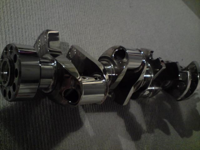
I thought I should put up a comparo of the two cranks I have, you can see where the extra weight is, from the ends the second counter weight and all the inner counter weights are much smaller on the Winberg.


Also Moldex only put lightening holes in one side of the journal. The hole is much smaller too.


The holes are 19 mm versus 22 mm and literally twice the material is removed. The difference is that the Moldex hole is basically perpendicular to the journal and the Winberg drills into the journal at 20 degrees and hollows out the journal much more.
Why is this important? Well there is a very good reason the more material you take from the rod journal obviously there is less weight at the further most point of the crank and all the implications of the mass force that can have but the more material that is taken from the journals means that you can take the same amount from the counter weight. So save 250 grams in the rod journal save another 250 grams on the counter weight.

There is also a lot of material that can be removed in the mains, much like Mike's cams. Also the heavy metal brings the weight of the crank down too, I am going to investigate to see whether it is possible to fit the heavy metal from the Winberg crank and trim up the crank in obvious areas and bring it down to 20 to 22 kgs.
I was reading in Race Engine Technology that concentrating on MOI, good gains are made in acceleration out of corners. If the crank can be reduced in weight safely, combined with the new clutch there will be a saving of weight in the rotating assembly and the clutch adding up to 22 kgs. That will certainly change the feel and responsive behaviour and of course gets another bag of cement out of the car.
Greg
Also Moldex only put lightening holes in one side of the journal. The hole is much smaller too.
The holes are 19 mm versus 22 mm and literally twice the material is removed. The difference is that the Moldex hole is basically perpendicular to the journal and the Winberg drills into the journal at 20 degrees and hollows out the journal much more.
Why is this important? Well there is a very good reason
the more material you take from the rod journal obviously there is less weight at the further most point of the crank and all the implications of the mass force that can have but the more material that is taken from the journals means that you can take the same amount from the counter weight. So save 250 grams in the rod journal save another 250 grams on the counter weight. There is also a lot of material that can be removed in the mains, much like Mike's cams. Also the heavy metal brings the weight of the crank down too, I am going to investigate to see whether it is possible to fit the heavy metal from the Winberg crank and trim up the crank in obvious areas and bring it down to 20 to 22 kgs.
I was reading in Race Engine Technology that concentrating on MOI, good gains are made in acceleration out of corners. If the crank can be reduced in weight safely, combined with the new clutch there will be a saving of weight in the rotating assembly and the clutch adding up to 22 kgs. That will certainly change the feel and responsive behaviour and of course gets another bag of cement out of the car.
Greg
10-31-2010, 11:28 AM
#69
Nordschleife Master
GG -- Your link cites an experiment which, if taken at face value, shows a big improvement from bull nosing and knife edging the crankshaft. Some people question this. Specifically, they say that whatever gains were recorded came from lower bearing frictions because the unintended consequence of bull nosing and knife edging the crank was counterweight distribution that lead to lower bearing loads. Notice how your Winberg doesn't have "aero" counterweights?
Everyone -- This crankshaft design stuff is a pretty involved, I understand that I don't understand jack-s about it. But the business side seems to be pretty easy to get a handle on. A lot of confusion in the performance aftermarket parts is created by people copying other peoples designs without understanding what their intended functions. Then crank makers will sell the customer whatever the customer wants. Finally, for profitable manufacturers, 50% of the performance aftermarket parts costs come from advertising, and the marketing department seems to come up with as many of the "innovations" as the engineering department.
If the use of these parts was something else than a frivolous hobby, all of this would be called "consumer fraud." I am talking about performance aftermarket, the big car factories sell well-engineered products. Just to be clear: I don't know anything about engineering. But I know consumer fraud, as I've studied financial markets my entire adult life... ;-)
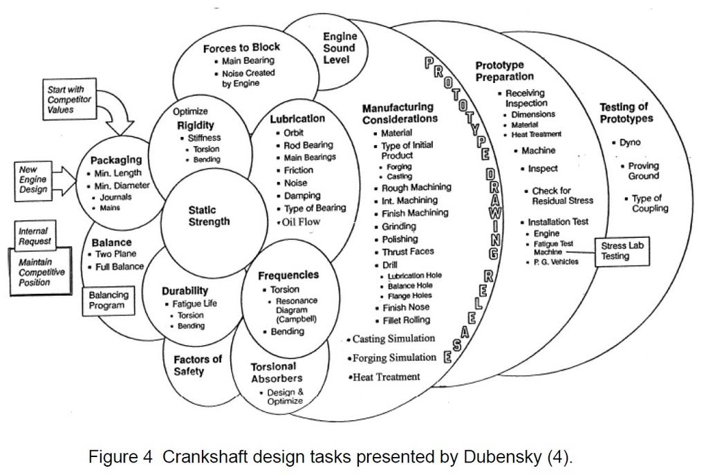
That all said, I find this stuff fascinating. The below image lists some other things that we'd have to discuss in this thread:
http://www.mime.eng.utoledo.edu/facu...temi26FITC.pdf
Everyone -- This crankshaft design stuff is a pretty involved, I understand that I don't understand jack-s about it. But the business side seems to be pretty easy to get a handle on. A lot of confusion in the performance aftermarket parts is created by people copying other peoples designs without understanding what their intended functions. Then crank makers will sell the customer whatever the customer wants. Finally, for profitable manufacturers, 50% of the performance aftermarket parts costs come from advertising, and the marketing department seems to come up with as many of the "innovations" as the engineering department.
If the use of these parts was something else than a frivolous hobby, all of this would be called "consumer fraud." I am talking about performance aftermarket, the big car factories sell well-engineered products. Just to be clear: I don't know anything about engineering. But I know consumer fraud, as I've studied financial markets my entire adult life... ;-)
That all said, I find this stuff fascinating. The below image lists some other things that we'd have to discuss in this thread:
http://www.mime.eng.utoledo.edu/facu...temi26FITC.pdf
11-02-2010, 07:25 PM
#70
Advanced
Join Date: Dec 2006
Location: finland
Posts: 71
Likes: 0
Received 0 Likes
on
0 Posts
Crankshaft would not be the most easiest part to use for learning....but very useful, because you'll have to deal with few quite nice programming tricks.
You'll for example use polar coordinate interpolation to machine rod pins and rotary 4-axis for counterweights... And so on. But almost everything else is just simple 3+2 axis programming.
I've been involved with Mazak Integrex e-series for quite some time. Those are totally fantastic machines!! You can do almost everything you can think with them, easy, efficient and fast. And also perfect for crank production. Also new Mori Seiki b-axis machines (similar to Mazak) are one of my favourites also.
You could do a crank programming with Mazatrol Matrix VERY fast without post processor and plane programming problems, only 'difficult' part is the G12.1 because you have to create a g-code eia/iso program for that...
Good luck with this project and keep us updated about!
http://www.youtube.com/watch?v=AV6m5_DZ-tk
11-02-2010, 09:38 PM
#71
Burning Brakes
Join Date: Jan 2007
Location: Austin TX
Posts: 1,213
Likes: 0
Received 0 Likes
on
0 Posts
Yep polar interpolation have fun with that! Look at how that thing floats around in three dimensions! The one in the schools shop was turret style - didn't quite have the capability of the Mazak in the movie, but close.
11-09-2010, 11:56 AM
#72
5th Gear

Join Date: Oct 2010
Posts: 5
Likes: 0
Received 0 Likes
on
0 Posts
ok i have a few questions, first, does anyone know what the bolt pattern is on the end of the crank? at first i thought it was just 9 holes equally spaced, but then i measured some centre to centres and some of them were different
secondly, what would be the best way to handle the oil path? the original crank i have here has them just drilled diagonally thru the side of the throw down to meet the journal and then directly to the main, but with the longer stroke that doesn't work, so either i have the hole go directly through the jounal (i've seen that done in some videos) or have several parallel and perpendicular holes drilled to line up, then they'd just need to be plugged on the ends, the only problem with that is some of the original journal holes aren't centred, can I just make then centre or is that something i shouldn't touch
hope that all made sense, i'm still not totally sure of all the proper terminology, thanks
03-18-2012, 06:53 AM
#73
I thought I should put up a comparo of the two cranks I have, you can see where the extra weight is, from the ends the second counter weight and all the inner counter weights are much smaller on the Winberg.
Also Moldex only put lightening holes in one side of the journal. The hole is much smaller too.
The holes are 19 mm versus 22 mm and literally twice the material is removed. The difference is that the Moldex hole is basically perpendicular to the journal and the Winberg drills into the journal at 20 degrees and hollows out the journal much more.
Why is this important? Well there is a very good reason the more material you take from the rod journal obviously there is less weight at the further most point of the crank and all the implications of the mass force that can have but the more material that is taken from the journals means that you can take the same amount from the counter weight. So save 250 grams in the rod journal save another 250 grams on the counter weight.
Also Moldex only put lightening holes in one side of the journal. The hole is much smaller too.
The holes are 19 mm versus 22 mm and literally twice the material is removed. The difference is that the Moldex hole is basically perpendicular to the journal and the Winberg drills into the journal at 20 degrees and hollows out the journal much more.
Why is this important? Well there is a very good reason
the more material you take from the rod journal obviously there is less weight at the further most point of the crank and all the implications of the mass force that can have but the more material that is taken from the journals means that you can take the same amount from the counter weight. So save 250 grams in the rod journal save another 250 grams on the counter weight. We were discussing piston guided rods and then it came to me that one of the reasons the 928 stroker crank ends up so heavy is that they use the Chevy rod journal width, yes width not just diameter, for those who have read some of my various posts I have always been critical of the stroker cranks with the large diameter journals which is the reason I had built some years ago a smaller rod journaled stroker crank as seen in the above pics.
That Honda journaled crank weighs the same as a standard stroke 928 crank despite having the 8 counterweights. I have also been a proponent of this design despite the added weight for the reasons of friction and bearing wear and most importantly block stability however this I believe is also related to mass forces from the rotating and reciprocating assembly.
Going back to excess weight in stroker cranks, the journals were always made to chevy width journals, I fell into this trap too when I designed the Honda journaled crank, this is not related to the issue of the bearings being offset, for the record I always thought that builders reversed the rods and then cut a chamfer on the crankshaft cheek side. That is what I intended to do. However by using these narrow crank guided rods you end up with very heavy crankshaft webs. Unless you have the earlier Scat cranks with undercut crank counterweights. These counterweights are much like these pictured below.

I know that the early Scat crankshafts with the 3.75" stroke weighed just 24 kilos and that is with the large 2.1" journal and no heavy metal in the counterweights. So with a reduced stroke, for the purpose of high speed operation, say like the 90 mm or 3.55" stroke crank that I had, it would be possible with less stroke, wider undercut and heavy metal weighted counterweights it would be possible to dip under 20 kilo range possibly around 40 pounds.
The Windberg crank in the comparison pics with my stroker crank has a very small amount of metal at the extremity of the crank throw. This area in a crank guided setup would rub against the side of the chamfered rod. The pic at the bottom doesn't even have this small area, obviously this area is important in terms of centrifugal forces. When compared to the stroker crank I had built the crank cheeks are positively massive, clearly there is a lot of weight there too and this material adds the equivalent material in weight to the counterweight. You can see how the Winberg even has that material on the side of the lightening holes cut down in a convex curve.
All these little differences add to the weight the crank carries and none of that extra weight necessarily adds any extra strength. If I get time I will add some pics to this or maybe another one of my threads as it might be too much off topic of the piston guided rods that I have. They are made from a very exotic steel called 35Nicrmo16 you can read about it's properties here, top quality rods are needed when piston guided rods are used, as the clearances needed are small and obviously need to be maintained under all operating conditions.
http://www.aubertduval.com/uploads/t...t/819AW_GB.pdf